Download - Australian Institute of Refrigeration Air Conditioning and ...
Download - Australian Institute of Refrigeration Air Conditioning and ...
Download - Australian Institute of Refrigeration Air Conditioning and ...

Create successful ePaper yourself
Turn your PDF publications into a flip-book with our unique Google optimized e-Paper software.
26<br />
FORUM<br />
Ammonia Absorption<br />
<strong>Refrigeration</strong> Plant<br />
D W Hudson, Gordon Brothers Industries Pty Ltd<br />
ABSTRACT:<br />
The application <strong>of</strong> ammonia absorption systems <strong>of</strong>fers many advantages <strong>and</strong> this paper will review the basic<br />
operating cycle, <strong>and</strong> investigate performance <strong>and</strong> economic benefits.<br />
Keywords: Ammonia, absorption, refrigeration cycle.<br />
INTRODUCTION<br />
<strong>Refrigeration</strong> plants using absorption principles have been<br />
around for many years with initial development taking place<br />
over 100 years ago.<br />
Although the majority <strong>of</strong> absorption cycles are based on<br />
water/lithium bromide cycle, many applications exist where<br />
ammonia/water can be used, especially where lower<br />
temperatures are desirable.<br />
In both systems water is used as working fluid, but in quite<br />
different ways: as a solvent for the ammonia-system, <strong>and</strong> as<br />
THE OFFICIAL JOURNAL OF AIRAH - august 2002<br />
refrigerant for the lithium bromide system. This explains that<br />
the lithium bromide absorption system is strictly limited to<br />
evaporation temperatures above 0ºC. On the other h<strong>and</strong>,<br />
water as a solvent in an ammonia absorption system has a<br />
vapour pressure that requires rectification, whereas LiBr - a<br />
hygroscopic salt - is non-volatile <strong>and</strong> the desorbed water<br />
vapour is free from solvent without the need for purification.<br />
The main industrial applications for refrigeration are in the<br />
temperature range below 0ºC, the field for the binary system<br />
ammonia-water.<br />
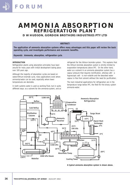
A typical ammonia absorption system is shown above.
Operation <strong>of</strong> the refrigeration cycle is conventional with high<br />
pressure liquid entering the liquid receiver from the condenser<br />
before passing to the evaporator where heat is absorbed from<br />
the process.<br />
The remaining items in the system replace the conventional<br />
compressor to achieve “thermal” compression in three steps.<br />
1. Absorption <strong>of</strong> the ammonia vapour in a weak ammoniawater<br />
solution at evaporation pressure.<br />
2. Transport <strong>of</strong> the strong ammonia water solution from<br />
evaporator pressure to condenser pressure.<br />
3. Removal <strong>of</strong> the ammonia from the ammonia-water solution<br />
(Desorption) at condenser pressure, together with the<br />
purification <strong>of</strong> the ammonia by heat energy.<br />
High pressure ammonia leaving the fractionator column<br />
passes to the condenser for the cycle to continue.<br />
It is important to note that the system must maintain a<br />
thermal balance with total heat input balancing with the<br />
total heat rejected. This provides a simple check on the<br />
plant, as a variation would indicate a design error.<br />
A description <strong>of</strong> each component in the plant follows:<br />
a. A conventional evaporative condenser is used which in<br />
fact is slightly smaller than for a conventional plant.<br />
Ammonia vapour leaving the fractionator column is not<br />
highly superheated which allows the condenser to operate<br />
without the need for desuperheating.<br />
b. The liquid receiver is conventional providing for variations<br />
in refrigerant volume flowing in the system.<br />
c. A plate heat exchanger is used for glycol chilling duties as<br />
in a conventional plant.<br />
d. The suction liquid heat exchanger E3 provides subcooling<br />
<strong>of</strong> the liquid <strong>and</strong> superheating <strong>of</strong> the suction gas. This<br />
heat exchanger is particularly important to improve the<br />
overall plant efficiency. The effect <strong>of</strong> a highly superheated<br />
gas at the absorber is not critical.<br />
e. The absorber is a critical plant item allowing the ammonia<br />
vapour to be absorbed into an ammonia water solution. It<br />
is a combined heat <strong>and</strong> mass transfer problem where a<br />
considerable quantity <strong>of</strong> heat is liberated which must be<br />
rejected to the ambient air or a cooling water system.<br />
Careful design <strong>of</strong> the absorber is important <strong>and</strong> thin film<br />
techniques over a tube bundle are normal to h<strong>and</strong>le the<br />
large differences in flow volumes between the ammonia<br />
vapour <strong>and</strong> the ammonia water solution.<br />
Evaporating pressure is set by the absorber <strong>and</strong> if it fails<br />
to reject the required heat <strong>of</strong> solution under maximum<br />
operating conditions, then evaporator pressure <strong>and</strong><br />
temperature will rise accordingly.<br />
Total heat rejected by the absorber is much greater than<br />
for the evaporator duty <strong>and</strong> this depends to some extent<br />
FORUM<br />
on the COP <strong>of</strong> the plant. Typically it can be over twice as<br />
much as the evaporating duty.<br />
f. The absorbate receiver collects the strong ammonia water<br />
solution from the absorber for pumping.<br />
g. A positive displacement pump or a high head centrifugal<br />
pump is used to lift the ammonia water solution from<br />
evaporator pressure to condenser pressure. The power<br />
required for this pump is only small as the volume flows<br />
are relatively low for the system. For industrial plants, the<br />
power consumed is negligible <strong>and</strong> can be minimised by<br />
optimisation <strong>of</strong> the plant design.<br />
h. The Aqua Heat Exchanger E1 reduces the temperature <strong>of</strong><br />
the ammonia water mixture from the fractionator column<br />
<strong>and</strong> preheats the feed to the column. This heat exchanger<br />
is also important to increase the overall cycle efficiency.<br />
In addition, for the absorber to work at peak efficiency,<br />
the weak ammonia-water solution must be as cool as<br />
possible.<br />
Heat exchanger E2 removes heat from the steam<br />
condensate to add further heat to the column feed.<br />
i. The fractionator column accepts the preheated feed from<br />
the Aqua-Heat Exchanger, where some desorption <strong>of</strong> the<br />
ammonia <strong>and</strong> water vapour occurs. It is divided into two<br />
sections each containing a fill material to aid the<br />
distillation process. The rectifying section is above the<br />
feed point <strong>and</strong> the stripping section is below the feed.<br />
Liquid ammonia from the receiver is introduced as reflux<br />
into the top <strong>of</strong> the column to allow the ammonia vapour<br />
to be purified with a residual water content <strong>of</strong> 100 ppm or<br />
less. Reflux adds to the quantity <strong>of</strong> heat required for the<br />
column <strong>and</strong> must be kept to a minimum, consistent with<br />
maintaining an acceptable vapour quality at the outlet.<br />
All liquid ammonia introduced as reflux must be<br />
evaporated by heat from the reboiler. To <strong>of</strong>fset the<br />
amount <strong>of</strong> heat for the reboiler a cold reflux from the<br />
absorbate pump can be used. This improves the heat ratio<br />
<strong>of</strong> the plant.<br />
In the stripping section, ammonia is stripped from the<br />
ammonia-water solution, as it contacts ammonia <strong>and</strong><br />
water vapour rising from the base <strong>of</strong> the column. The<br />
stripped solution is not allowed to mix with the weak<br />
ammonia-water solution in the base <strong>of</strong> the column, as a<br />
mixture would necessitate a higher column temperature.<br />
Instead the stripped solution passes to the reboiler<br />
(desorber) where heat is added to drive the process.<br />
A considerable difference in temperature occurs over the<br />
column length with the highest temperature at the base,<br />
falling to condensing temperature at the top <strong>of</strong> the<br />
column. This fact allows heat to be introduced into the<br />
column at various levels, if desired.<br />
THE OFFICIAL JOURNAL OF AIRAH - august 2002<br />
27
FORUM<br />
At the base <strong>of</strong> the column a weak ammonia-water solution<br />
is collected before passing to the Aqua-Heat Exchanger<br />
<strong>and</strong> absorber for re-use.<br />
j. The reboiler accepts the stripped ammonia-water solution<br />
from the column <strong>and</strong> adds heat to drive the ammonia from<br />
the water.<br />
It is possible to pump the ammonia-water solution<br />
through the reboiler, but this only adds unnecessary<br />
complications to the circuit.<br />
During the heating process, some water vapour is driven<br />
<strong>of</strong>f with the ammonia <strong>and</strong> this is why it is important for<br />
the fractionator column to remove as much moisture as<br />
possible using well designed reflux for the column.<br />
The mechanical vapour compression system is shown below<br />
to illustrate the differences in complexity <strong>of</strong> the two<br />
systems.<br />
Mechanical Vapour Compression<br />
CO-EFFICIENT OF PERFORMANCE<br />
Co-efficient <strong>of</strong> performance (COP) is defined as the ratio <strong>of</strong><br />
refrigeration effect, divided by the heat or power input. For<br />
an Absorption system this is generally below unity, although<br />
it is theoretically possible to obtain figures well above unity.<br />
Losses in the system <strong>and</strong> thermodynamic irreversibilities will<br />
generally prevent a COP greater than one for refrigeration<br />
cycles.<br />
The co-efficient <strong>of</strong> performance is also known as the Heat<br />
Ratio in absorption systems <strong>and</strong> can be shown as follows:<br />
Coefficient <strong>of</strong> Performance = Refrig Effect<br />
(Heat Ratio) Heat Input<br />
Theoretical Carnot COP = (Tevap ) (Tgen - Tcond)<br />
(Absorption Plant) (Tcond - Tevap ) ( Tgen )<br />
Theoretical Carnot COP = Tevap<br />
(Mechanical Plant) (Tcond-Tevap)<br />
Tevap = Absolute evaporating temperature (k)<br />
Tcond = Absolute condensing temperature (k)<br />
28 THE OFFICIAL JOURNAL OF AIRAH - august 2002<br />
Tgen = Absolute generator temperature (k)<br />
It is important to note that the COP for an absorption plant<br />
is the same as for a mechanical plant but is modified by the<br />
COP <strong>of</strong> the heat engine to drive the plant. If the COP <strong>of</strong> the<br />
power generating station together with transmission losses<br />
were added to the mechanical system then the overall COP <strong>of</strong><br />
both systems become much closer.<br />
Typical COP<br />
Calculation <strong>of</strong> COP that can be expected from an absorption<br />
plant <strong>and</strong> a mechanical vapour compressor system is given<br />
below.<br />
Operating Conditions<br />
Tevap = 253 K (-20ºC)<br />
Tcond = 308 K (+35ºC)<br />
Tabs = 308 K (+35ºC)<br />
Tgen = 423 K (150ºC)<br />
Carnot COPabs = 1.251 Practical COPabs = 0.6<br />
Carnot COPmvc = 4.6 Practical COPmvc = 2.75<br />
Tabs = Absolute absorber temperature (k)<br />
Comparison <strong>of</strong> COP<br />
Co-efficient performance is affected by evaporating<br />
temperature <strong>and</strong> from the above figure it is quite evident that<br />
the co-efficient <strong>of</strong> performance <strong>of</strong> the two systems are vastly<br />
different. The COP for the absorption plant is much less<br />
affected by a drop in evaporating temperature <strong>and</strong> this is a<br />
significant advantage in overall economy.<br />
A number <strong>of</strong> other factors also affect COP in an absorption<br />
refrigeration plant <strong>and</strong> these are:<br />
• Column temperature<br />
• Ammonia purity (reflux ratio)<br />
• Condensing temperature<br />
• Cold reflux ratio
• Absorber temperature<br />
• Heat exchanger effectiveness<br />
Source Temperatures<br />
There is almost a direct relationship between the maximum<br />
temperature <strong>of</strong> the fractionator column, the condensing<br />
temperature <strong>and</strong> the evaporating temperature.<br />
As the condensing temperature increases, the base<br />
temperature <strong>of</strong> the column increases. Also as the evaporating<br />
temperature decreases, then the base temperature <strong>of</strong> the<br />
column increases <strong>and</strong> this is shown below.<br />
For low temperature applications, high grade waste heat is<br />
essential, but if this is not available, then economic<br />
operation is quite possible using direct steam or gas heating.<br />
It is also important to note the thermal gradient in the<br />
fractionator column means that heat can be added at lower<br />
temperatures at strategic points in the column. This reduces<br />
the quantity <strong>of</strong> heat required at maximum temperature, but<br />
may enable other heating sources to be utilised.<br />
OPERATING ECONOMICS<br />
Even though the thermal efficiency <strong>of</strong> the absorption plant is<br />
quite low, the direct operating costs must be considered in<br />
evaluating the plant.<br />
Running Cost Comparisons (500 kW Plant)<br />
FORUM<br />
The above figure compares the expected running cost per<br />
hour for a mechanical vapour compression system using power<br />
at a cost <strong>of</strong> 8.5c/kWhr <strong>and</strong> also an ammonia absorption<br />
refrigeration system using steam generated from a boiler at<br />
costs <strong>of</strong> $10, $15 <strong>and</strong> $20 per tonne <strong>of</strong> steam produced.<br />
The upper curve is for $20 tonne <strong>of</strong> steam produced <strong>and</strong> at<br />
this level the AAR plant cannot compare with a conventional<br />
plant. However at lower costs <strong>of</strong> $15 <strong>and</strong> $10 / tonne the<br />
AAR plant does have lower running costs as the evaporating<br />
temperatures become lower.<br />
CAPITAL COST<br />
Preliminary estimates indicate that the ammonia absorption<br />
plant would be 20% to 30% more expensive than<br />
conventional equipment in sizes above 350 kW capacity. This<br />
only compares equipment costs, <strong>and</strong> does not include services<br />
such as transformers, electrical starters, electrical mains <strong>and</strong><br />
buildings, which are all required for a conventional plant, but<br />
are not required for the absorption system.<br />
ADVANTAGES<br />
There are a number <strong>of</strong> advantages for Ammonia Absorption<br />
<strong>Refrigeration</strong> Plants which need consideration:<br />
1. The equipment produces no noise other than pumps, which<br />
are small low power units.<br />
Noise is a major problem with plant rooms, <strong>and</strong> with<br />
tighter specifications, conventional systems with screw<br />
compressors are difficult <strong>and</strong> expensive to attenuate.<br />
2. There is no oil the system <strong>and</strong> the plant requires no oil<br />
management. In a new plant, oil will not contaminate<br />
heat exchange surfaces, which, if kept clean, will always<br />
deliver maximum performance.<br />
Oil is always a problem in ammonia systems, with a<br />
continuous loss to the system occurring. Recovery is<br />
difficult <strong>and</strong> the oil is normally unsuitable for re-use in<br />
the system.<br />
3. If waste heat is available, running costs are very low, as<br />
only condenser fans, aqua pumps <strong>and</strong> absorber fans need<br />
to be powered.<br />
In a conventional system, the compressor will absorb up<br />
to 90% <strong>of</strong> the total power used. If waste heat is available<br />
at the right temperature, then the power savings are very<br />
significant.<br />
4. High turn down ratios are possible, giving efficient part<br />
load performance.<br />
Generally speaking, all refrigeration plants are only sized<br />
for peak load conditions. For the majority <strong>of</strong> the time,<br />
plants run at part load, with low efficiencies. Screw<br />
compressors at high compression ratios have particularly<br />
poor part load characteristics, resulting in excessive power<br />
consumption.<br />
THE OFFICIAL JOURNAL OF AIRAH - august 2002<br />
29
FORUM<br />
5. The number <strong>of</strong> moving parts is restricted to fans <strong>and</strong><br />
pumps, which are easy to service <strong>and</strong> give long troublefree<br />
life. Maintenance costs are low, as there are no<br />
expensive compressors to maintain.<br />
6. Ammonia Absorption Plants can be fitted to existing<br />
systems to replace conventional compressors or<br />
supplement existing capacity.<br />
7. The fractionating column <strong>and</strong> condenser can be located<br />
several hundred meters from the evaporator <strong>and</strong> absorber,<br />
with small interconnecting lines, which need not be<br />
insulated. This permits maximum flexibility in plant<br />
layout, without compromising overall efficiency. This is<br />
simply not practical with a conventional plant, due to<br />
system pressure drops.<br />
8. For AAR plants, plant rooms are not required, as the<br />
absorber must be located outside <strong>and</strong> the fractionating<br />
column can be conveniently located at the heat source.<br />
Savings in building costs would be substantial.<br />
9. As the dem<strong>and</strong> for electric power is minimal, the need for<br />
large transformers <strong>and</strong> electrical mains, normally<br />
associated with a refrigeration plant, is eliminated. This<br />
cost is <strong>of</strong>ten overlooked in the cost <strong>of</strong> conventional<br />
refrigeration equipment <strong>and</strong> yet it is fundamental to the<br />
operation <strong>of</strong> the plant.<br />
10.Liquid carryover is not a problem with Absorption Plants,<br />
as there are no moving parts to damage. In certain<br />
instances, liquid carryover from evaporators can be<br />
desirable, to prevent the build-up <strong>of</strong> water in the<br />
evaporator.<br />
30 THE OFFICIAL JOURNAL OF AIRAH - august 2002<br />
Liquid carryover in conventional plants is a major reason<br />
for compressor failures. Its causes are many, <strong>and</strong> even<br />
well maintained plants can suffer, due to sudden load<br />
changes or control malfunctions.<br />
11.No upper limit for the size <strong>of</strong> the plant.<br />
12.Waste heat can be conveniently converted to refrigeration,<br />
without the need for conversion to electrical energy.<br />
DISADVANTAGES<br />
There are some disadvantages with an ammonia absorption<br />
plant <strong>and</strong> these are detailed below.<br />
• Capital cost higher than mechanical plant<br />
• More complex refrigeration system<br />
• High grade heat required<br />
• More space required<br />
• Perception that it is outdated technology<br />
CONCLUSION<br />
The Ammonia Absorption <strong>Refrigeration</strong> Plant <strong>of</strong>fers a number<br />
<strong>of</strong> advantages at temperatures below 0ºC <strong>and</strong> where waste<br />
heat or cheap steam is available, significant running costs<br />
savings can be made.<br />
With flexibility in operation, absence <strong>of</strong> compressor noise,<br />
very low maintenance <strong>and</strong> high reliability, industrial Ammonia<br />
Absorption Plants, should be considered as a viable<br />
alternative to mechanical vapour compression plants.<br />
AIR-FLOW MEASURING INSTRUMENTATION<br />
•<br />
sales repair calibration<br />
•<br />
•<br />
• ANEMOMETERS • AIR-FLOW HOODS<br />
• MANOMETERS • PITOT TUBES<br />
• VELOMETERS • AIR-FLOW MONITORS<br />
<strong>Australian</strong> distributors for Alnor Instruments<br />
CALL FOR A FREE PRODUCT CATALOGUE<br />
Full service <strong>and</strong> calibration facilities available<br />
for Alnor <strong>and</strong> other br<strong>and</strong> name instruments<br />
Unit 1/20 Kareena Road North<br />
MIRANDA, NSW 2228 AUSTRALIA<br />
Tel: (02) 9540 4626<br />
Fax: (02) 9540 2351<br />
e-mail: info@flowcal.com.au<br />
Web site: www.flowcal.com.au