Thermal Bridging Chart - Australian Institute of Refrigeration Air ...
Thermal Bridging Chart - Australian Institute of Refrigeration Air ...
Thermal Bridging Chart - Australian Institute of Refrigeration Air ...

Create successful ePaper yourself
Turn your PDF publications into a flip-book with our unique Google optimized e-Paper software.
20<br />
FORUM<br />
<strong>Thermal</strong> <strong>Bridging</strong> <strong>Chart</strong><br />
- A New Way <strong>of</strong> <strong>Thermal</strong> Evaluation<br />
Gang Wei M.E. (Mech), B.E. (Mech)<br />
<strong>Air</strong> Design Pty Ltd<br />
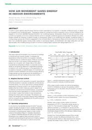
ABSTRACT<br />
Based on the thermal bridging factor kb introduced by BS EN 1886:1998, a method <strong>of</strong> determining and evaluating the<br />
thermal bridging property <strong>of</strong> air handling unit components has been developed. A thermal bridging chart has been<br />
designed on which the thermal bridging properties <strong>of</strong> components and the ambient conditions can be presented and<br />
compared to determine whether condensation would occur. The method introduced would give both manufacturers and<br />
users confidence in designing, specifying and evaluating air handling units in terms <strong>of</strong> surface condensation - one <strong>of</strong> the<br />
major concerns in the <strong>Australian</strong> application environment.<br />
1. INTRODUCTION<br />
<strong>Thermal</strong> bridging, or cold tracking as it is <strong>of</strong>ten referred, is a term that<br />
describes the unwanted ability <strong>of</strong> a component to transfer thermal<br />
energy from one side to the other. Strictly speaking, this property is not<br />
simply an opposite term to insulation. The “unwanted” nature <strong>of</strong> the<br />
term differs itself from terms like conductivity. More importantly this<br />
unwanted property normally has to be dealt with at the component level<br />
and cannot be averaged throughout the unit.<br />
There are two principle issues to consider when designing the insulation<br />
<strong>of</strong> an air handling unit: (1) overall thermal efficiency <strong>of</strong> the structure<br />
and (2) thermal bridging properties <strong>of</strong> each component. The former is an<br />
averaged effect <strong>of</strong> insulation throughout the unit while the later is<br />
related to each component <strong>of</strong> the structure. Note that the thermal<br />
bridging property should not be averaged. For example if we drive a<br />
screw through a well insulated air handling unit casing, the thermal<br />
efficiency may not be significantly affected as the sectional area <strong>of</strong> the<br />
screw is insignificant compared with the rest <strong>of</strong> the casing structure.<br />
However it could cause a thermal bridging effect, which would cause<br />
condensation on the surface and consequently corrosion <strong>of</strong> itself and<br />
adjacent components.<br />
Practically the test is whether condensation occurs on the surface <strong>of</strong><br />
components or not. It is a simple yes/no question; to answer it we have<br />
to understand both the thermal property <strong>of</strong> each component and the<br />
requirement <strong>of</strong> this property against given ambient conditions.<br />
The thermal property <strong>of</strong> a component can be improved if necessary by<br />
altering the design and/or material. When the thermal property meets<br />
the requirement, i.e. no condensation would occur, further improvement<br />
(which is usually expensive) is unnecessary. Clearly it requires a method<br />
<strong>of</strong> measurement <strong>of</strong> thermal bridging property <strong>of</strong> components. The<br />
measurement would then be examined against a criteria to determine<br />
whether condensation would occur. This criteria is also a function <strong>of</strong> the<br />
ambient condition i.e. inside temperature, outside temperature and<br />
humidity <strong>of</strong> the air, which varies from place to place and time to time.<br />
Clearly, in order to evaluate the thermal bridging property we need:<br />
(1) a parameter that describes the thermal bridging (or anti-thermalbridging)<br />
property <strong>of</strong> a component that can be easily determined<br />
either theoretically or experimentally.<br />
(2) a method that interprets the parameter in terms <strong>of</strong> whether<br />
condensation would occur under given ambient conditions.<br />
THE OFFICIAL JOURNAL OF AIRAH<br />
A thermal bridging factor k b has been introduced by the British standard<br />
BS EN 1886:1998 [1] , which is the ratio <strong>of</strong> temperature difference<br />
between outside surface and inside air to that between outside air and<br />
inside air. The standard also introduced a testing method in determining<br />
k b and classification <strong>of</strong> the factor. The standard however restricts the<br />
test conditions, which makes it difficult to apply the method to<br />
installed cooling units. Also, the k b factor and its classification does not<br />
directly relate to the fundamental question - will condensation occur?<br />
In this paper the suitability <strong>of</strong> the thermal bridging factor k b (BS EN<br />
1886:1998) to the <strong>Australian</strong> applications has been examined. Our<br />
further development in adapting the concept and using it for predicting<br />
surface condensation is reported.<br />
2. THE k b FACTOR<br />
BS EN 1886:1998 is a standard that specifies mechanical performance <strong>of</strong><br />
air handling units, including structural strength, thermal, leakage and<br />
acoustic performances. In this standard a thermal bridging factor k b is<br />
defined as follows:<br />
where<br />
the least temperature difference between mean internal air<br />
temperature and maximum external surface temperature (when<br />
internal temperature is higher)<br />
air-to-air temperature difference.<br />
(1)<br />
To determine the above, it is required by the standard to remove all<br />
mounted internal equipment such as fans and coils, increase the internal<br />
temperature and set the temperature difference Dtair to 20-25k before<br />
the surface temperatures are measured.<br />
The kb factor provides a description <strong>of</strong> thermal bridging property <strong>of</strong> air<br />
handling units, with which air handling units can be specified and<br />
compared in terms <strong>of</strong> thermal bridging property. The standard also gives<br />
a classification <strong>of</strong> the factor:<br />
Table 1 Classification <strong>of</strong> k b<br />
Class TB1<br />
Class TB2<br />
Class TB3<br />
Class TB4<br />
Class TB5<br />
There are however drawbacks to the specification:<br />
(1) First the difficulty <strong>of</strong> applying the method due to restricted test<br />
conditions specified. e.g. it is not practical to determine the k b<br />
factor <strong>of</strong> an installed cooling unit.<br />
(2) Secondly, the kb factor and its classification has not been directly<br />
related to predicting the surface condensation <strong>of</strong> a unit or its<br />
components. No criteria is established which is as important as the<br />
parameter itself.<br />
2. THE COMPONENT APPROACH<br />
Although the standard tends to use the k b as a factor to describe the<br />
overall property <strong>of</strong> a unit by using the least temperature difference<br />
(associated with the most thermal bridging component) in calculation,<br />
we found it is more convenient to establish kb for individual<br />
components, i.e.<br />
where<br />
external surface temperature (°C) <strong>of</strong> the component concerned<br />
mean external air temperature (°C)<br />
mean internal air temperature (°C)<br />
0.75 < kb < 1<br />
0.6 < kb < 0.75<br />
0.45 < kb < 0.6<br />
0.3 < kb < 0.45<br />
0 < kb < 0.3<br />
(2)<br />
Conceptually, the k b factor now is a property <strong>of</strong> a given component (not<br />
that <strong>of</strong> a unit). This (together with the thermal bridging chart<br />
introduced later) is useful for mapping out the thermal bridging<br />
property across the unit.<br />
Consider the following model:<br />
Figure 1 Model <strong>of</strong> a component<br />
FORUM<br />
There are three layers in this model: the component <strong>of</strong> thermal<br />
resistance R is between the inside and outside air with Rair-1 and Rair-2<br />
(they are different as the inside air is usually moving and outside air is<br />
considered as still). As the inside surface temperature is not concerned<br />
we combine the component and the inside air into one layer, i.e.<br />
Considering the energy transferred through the layers [3,4,5] we have:<br />
The outside surface temperature can then be found by:<br />
Substitute (5) into (2):<br />
(3)<br />
(4)<br />
(5)<br />
(6)<br />
Equation (6) shows that the k b factor is a function <strong>of</strong> the thermal<br />
resistance <strong>of</strong> the component as well as that <strong>of</strong> inside and outside<br />
surface layer <strong>of</strong> air. If the inside and outside air are taken as constants<br />
(i.e. considering the inside air as moving within a specified speed range<br />
and outside air is close to still), the k b factor is then purely a property<br />
<strong>of</strong> the component.<br />
Because the k b factor is independent <strong>of</strong> the temperatures, theoretically<br />
it can be measured regardless <strong>of</strong> the operating and ambient<br />
temperatures as long as there is a temperature difference (to-ti>0,<br />
Equation 2). However, practically the accuracy <strong>of</strong> the measurement is<br />
affected by the temperature difference between outside and inside air.<br />
This can be seen from Equation (2), i.e. for a given instrument accuracy<br />
THE OFFICIAL JOURNAL OF AIRAH<br />
G<br />
21
FORUM<br />
cont. from page 21<br />
(e.g. ±0.2°C) the smaller the temperature difference the less accurate<br />
the k b factor will be. In Australia, the temperature inside an air<br />
handling units is normally from 10 to 12°C and typical outside<br />
temperatures can be from 24 to 34°C, i.e. the difference can be 12 to<br />
24k - a large portion <strong>of</strong> it is outside the 20k temperature difference<br />
specified by BS EN 1886:1998. If this 20k temperature difference can be<br />
reduced to 12k, it would mean that the k b factor can be obtained easily<br />
on site for most <strong>of</strong> the units in Australia.<br />
The following is a comparison <strong>of</strong> k b accuracy when the inside and<br />
outside temperature difference is 12k and 20k, assuming a measurement<br />
accuracy <strong>of</strong> ±0.2k:<br />
Table 2 Accuracy <strong>of</strong> k b when T o-t i = 12k<br />
kb To-ti max kb min kb + -<br />
0.5 6 0.55 0.45 10% 10%<br />
0.6 7.2 0.65 0.55 9% 8%<br />
0.7 8.4 0.75 0.65 8% 7%<br />
0.8 9.6 0.86 0.75 7% 7%<br />
0.9 10.8 0.96 0.84 6% 6%<br />
Table 3 Accuracy <strong>of</strong> k b when T o-t i = 20k<br />
kb To-ti max kb min kb + -<br />
0.5 10 0.53 0.47 6% 6%<br />
0.6 12 0.63 0.57 5% 5%<br />
0.7 14 0.73 0.67 5% 5%<br />
0.8 16 0.83 0.77 4% 4%<br />
0.9 18 0.93 0.87 4% 4%<br />
From Table 2 and Table 3 we can see that for the k b range <strong>of</strong> 0.5 to 0.9<br />
the difference in accuracy <strong>of</strong> the two is up to 4%. This number drops to<br />
2% at the higher end <strong>of</strong> k b. It is therefore safe to use the inside/outside<br />
temperature difference <strong>of</strong> as low as 12k without losing much resolution.<br />
This can be clearly seen from Figure 3 where the error value <strong>of</strong> k b is<br />
plotted against the inside/outside temperature difference for a k b value<br />
<strong>of</strong> 0.6.<br />
Figure 3 k b accuracy vs temperature difference<br />
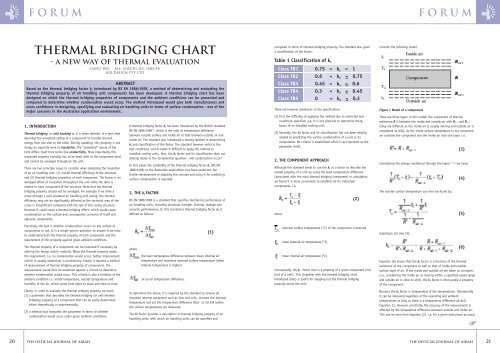
4. THE THERMAL BRIDGING CHART<br />
As pointed out previously although the k b factor reflects the thermal<br />
property <strong>of</strong> individual structural components, by itself it does not<br />
indicate whether surface condensation would occur. For this reason we<br />
have developed a thermal bridging chart, on which the k b factor <strong>of</strong><br />
components and the local dew point can be compared.<br />
A chart for inside temperature <strong>of</strong> 12°C is shown in Figure 2. In the<br />
chart, the x axis represents the outside air temperature; the left y axis<br />
represents inside air temperature, the surface temperature <strong>of</strong><br />
components and the ambient dew point temperature; the right y axis<br />
indicates the k b value. The values <strong>of</strong> k b are represented by lines<br />
starting from [12, 12] , i.e. when both inside and outside temperatures are<br />
12°C. The right y axis is scaled from 0 to 1, corresponding to the<br />
situations when external surface temperature is equal to inside air<br />
temperature (k b = 0) and when the external surface temperature is the<br />
same as the outside air temperature (k b = 1).<br />
Obviously, all temperatures and dew points must be between these<br />
two lines.<br />
When the inside temperature is a constant, the surface temperature<br />
becomes a linear function <strong>of</strong> the outside temperature (Equation 2).<br />
Therefore each component can be represented by a straight line, from<br />
which the surface temperature can be easily found from the y axis for<br />
any given outside temperature (x axis).<br />
The k b factor <strong>of</strong> components can be easily found by extending the<br />
lines representing components to the right y axis.<br />
The local dew point (the maximum ambient temperature that<br />
condensation occurs) is represented by points, i.e. dew point<br />
temperature (y) against ambient air temperature (x).<br />
Whether a component will cause condensation can then be clearly<br />
seen by checking whether the line representing the component is<br />
above the dew point.<br />
In the chart the classification <strong>of</strong> k b defined by BS EN 1886:1998 is<br />
also reserved (the areas separated by the corresponding k b lines)<br />
FORUM<br />
5. APPLICATION OF THE THERMAL BRIDGING CHART<br />
This method has been used in our development process for air<br />
handling units to evaluate the thermal bridging property <strong>of</strong><br />
components. The k b factor <strong>of</strong> components has been obtained from<br />
both theoretical calculations and experimental methods.<br />
Figure 2 The thermal bridging chart for inside temperature <strong>of</strong> 12°C Figure 4 Application <strong>of</strong> the thermal bridging chart<br />
Figure 4 shows the thermal bridging property <strong>of</strong> structural<br />
components air handling units together with the critical dew point<br />
temperatures at different locations extracted from the HVAC System<br />
Design Handbook [2] . Note that here only two components with the<br />
highest and lowest k b values are presented (the panel and the<br />
structural rails) for clarity as other components are in between.<br />
At the development stage, the component with the lowest kb value<br />
was first identified. Different designs <strong>of</strong> the component were then<br />
made to achieve higher values <strong>of</strong> k b until it was well above the<br />
nominated dew points (design criteria). The k b factor <strong>of</strong> each design<br />
was calculated theoretically. Selected designs were then prototyped<br />
and the k b verified experimentally. As the particular component was<br />
improved other component became the focus (with lower k b). This<br />
processes was repeated to the components with lower kb values until<br />
an optimized arrangement was found (in terms <strong>of</strong> both performance<br />
and cost).<br />
Figure 4 shows the final stage <strong>of</strong> panels and rails as well as the<br />
original design <strong>of</strong> the rails. The improvement <strong>of</strong> rails is clearly shown.<br />
The final design <strong>of</strong> these components are within TB1 zone and well<br />
above the dew points, indicating that condensation would not occur<br />
for those conditions.<br />
22 THE OFFICIAL JOURNAL OF AIRAH<br />
THE OFFICIAL JOURNAL OF AIRAH<br />
G<br />
23
FORUM<br />
cont. from page 23<br />
This method should not be restricted to air handling units. It may be<br />
applied to any components that require control <strong>of</strong> thermal bridging<br />
properties, e.g. air conditioning duct work.<br />
Generally it can be used in the following way:<br />
• Determine k b value <strong>of</strong> the component concerned either theoretically<br />
or experimentally or both (refer to section 6 below).<br />
• Plot the component onto the chart.<br />
• Plot also the criteria due point (either given in specifications or<br />
extracted from handbooks)<br />
• The chart would then clearly show 1) if the component is well above<br />
the due points, meaning no condensation; 2) which TB zone the<br />
component is in.<br />
• Repeat the above for other components <strong>of</strong> the structure concerned.<br />
All components can be plotted on one chart, providing a better<br />
comparison.<br />
6. DETERMINING k b<br />
As mentioned above the k b value <strong>of</strong> components can be obtained from<br />
either theoretical calculation or experimental measurement. Theoretical<br />
determination <strong>of</strong> k b varies depending on the complexity <strong>of</strong> the<br />
component and the way it is modeled. This will be dealt with elsewhere.<br />
To measure the k b value <strong>of</strong> a component we need to create a<br />
temperature difference between the inside and out side air. Knowing<br />
that k b is independent <strong>of</strong> temperature and the temperature difference<br />
can be as low as 12k without compromising the measurement accuracy<br />
(refer to section 3 above), we can use either heating or cooling to<br />
achieve these temperatures. In the laboratory a box <strong>of</strong> ice or a heater<br />
with a suitable circulating fan can be placed inside the unit casing<br />
being tested. For installed units the temperature difference is normally<br />
readily available when the unit is running.<br />
Once the temperature difference is established and becomes stable, the<br />
inside temperature, outside temperature and the temperature on the<br />
surface <strong>of</strong> components can be measured and recorded. Equation 2 can<br />
then be applied to calculate the k b value for each component.<br />
7. DISCUSSIONS<br />
The above method provides a useful tool that quantifies the thermal<br />
bridging property <strong>of</strong> components and evaluates it against surface<br />
condensation. Through a large number <strong>of</strong> measurements, both in our<br />
laboratory and from installed units, we found that a satisfactory<br />
accuracy can be achieved with a lower temperature difference than that<br />
required by BS EN 1886. However we did maintain a minimum<br />
temperature difference <strong>of</strong> 12k.<br />
The accuracy <strong>of</strong> measurement can also be affected by the movement <strong>of</strong><br />
air, as this alters the thermal property <strong>of</strong> the surface layer <strong>of</strong> air. Care<br />
should therefore be taken when the unit being measured is either<br />
installed externally or in a plant room where air is moving through the<br />
room. In our laboratory testing we managed to maintain an inside<br />
surface air velocity similar to that found in a running air handling unit.<br />
The outside air was kept as still as possible.<br />
It is necessary to standardise the conditions <strong>of</strong> measurement so that the<br />
results are comparable and to a satisfactory accuracy. This should be<br />
considered in the development <strong>of</strong> the <strong>Australian</strong> version <strong>of</strong> the standard.<br />
8. CONCLUSIONS<br />
Based on both our theoretical analysis and experimental verification,<br />
the following conclusions can be made:<br />
(1) The concept <strong>of</strong> the thermal bridging factor k b introduced in BS EN<br />
1886:1998 is appropriate for measuring thermal bridging property <strong>of</strong><br />
air handling unit casing components.<br />
(2) It is appropriate to associate the k b factor to individual components<br />
<strong>of</strong> an air handling unit. This allows the designers to map the<br />
thermal bridging property <strong>of</strong> a unit in order to control, improve and<br />
balance the property among components. For the users it means<br />
better understanding and therefore higher confidence.<br />
(3) The temperature difference <strong>of</strong> 20k required by BS EN 1886:1998 for<br />
measurement <strong>of</strong> k b can be reduced to 12k with a satisfactory<br />
accuracy.<br />
(4) There is no difference in setting the inside temperature higher or<br />
lower than the outside temperature when measuring k b<br />
(5) <strong>Air</strong> movement affects the k b measurement and therefore needs to be<br />
controlled in a consistent manner when measuring k b.<br />
(6) The thermal bridging chart provides an accurate and yet easy-to-use<br />
method for mapping the thermal bridging property <strong>of</strong> components<br />
and determining surface condensation.<br />
(7) Further standardisation is necessary to adapt the concept and<br />
define test conditions for the <strong>Australian</strong> applications.<br />
About the Author<br />
Gang Wei is the Mechanical and Development Engineer/QA manager for<br />
<strong>Air</strong> Design Pty Ltd (Supplier <strong>of</strong> air handling units and air movement<br />
equipment).<br />
His responsibilities include new product development, engineering<br />
design, applications engineering, testing, as well as maintaining the<br />
quality system.<br />
Reference<br />
1. BS EN 1886:1998 Ventilation for buildings- <strong>Air</strong> handling units -<br />
Mechanical performance.<br />
2. The <strong>Australian</strong> <strong>Institute</strong> <strong>of</strong> <strong>Refrigeration</strong> <strong>Air</strong> Conditioning and Heating<br />
(inc.) Hand Book, 2nd Ed 1995<br />
3. Jones W. P. <strong>Air</strong> Conditioning Engineering, 4th Ed. Arnold 1994<br />
4. Haines R.W. and Wilson C.L. HVAC System Design Handbook, 2nd Ed<br />
MacGraw-Hill 1994<br />
5. Grimm N.R. and Rosaler R.C. Handbook <strong>of</strong> HVAC Design, MacGraw-<br />
Hill 1990<br />
AIRAH<br />
engineering a bEtter built environment<br />
FORUM<br />
JOIN AIRAH<br />
Call Joanna Roch at the National Office on (03) 9614 8868. Or simply fill in the<br />
form below and send it back to us by fax (03) 9614 8949 or mail to AIRAH,<br />
7/1 Elizabeth Street, Melbourne, VIC, 3000. Alternatively email your contact<br />
details to membership@airah.org.au<br />
AND RECEIVE<br />
• AIRAH handbook<br />
• AIRAH monthly journal<br />
• Industry Accreditation<br />
• State/territory activities<br />
• Networking<br />
• Member discounts on<br />
technical publications and<br />
industry training courses<br />
• Special Interest groups<br />
YES, I am interested in enjoying the benefits <strong>of</strong> AIRAH membership.<br />
Please contact me with more information.<br />
Name: ......................................................Position: ....................................<br />
Company Name:............................................................................................<br />
Address: ......................................................................................................<br />
................................................................State ..........Postcode ..................<br />
B/h Phone: ................................................Mob: ..........................................<br />
Email: ........................................................................................................<br />
24 THE OFFICIAL JOURNAL OF AIRAH<br />
THE OFFICIAL JOURNAL OF AIRAH<br />
✃<br />
25
FORUM<br />
FORUM<br />
26 THE OFFICIAL JOURNAL OF AIRAH<br />
THE OFFICIAL JOURNAL OF AIRAH<br />
27
FORUM<br />
FORUM<br />
28 THE OFFICIAL JOURNAL OF AIRAH<br />
THE OFFICIAL JOURNAL OF AIRAH<br />
29
FORUM<br />
FORUM<br />
30 THE OFFICIAL JOURNAL OF AIRAH<br />
THE OFFICIAL JOURNAL OF AIRAH<br />
31