EOLO EXTRA 32 kW X TV 32 kW - Immergas
EOLO EXTRA 32 kW X TV 32 kW - Immergas
EOLO EXTRA 32 kW X TV 32 kW - Immergas

Create successful ePaper yourself
Turn your PDF publications into a flip-book with our unique Google optimized e-Paper software.
1 FEATURES<br />
Wall-hung, room sealed, fan assisted boiler for central heating<br />
only, with a nominal heating output of <strong>32</strong> <strong>kW</strong> (27,520 kcal/h),<br />
with a high performance, forced circulation and made for use<br />
with a separate Storage Tank with capacities of 80, 105, 120<br />
and 200 litres.<br />
By varying the type of installation, boiler classification also<br />
varies.<br />
OUTDOOR INSTALLATION (in the open):<br />
Appliance type C - if installed using the compulsory (optional)<br />
top covering kit and the exhaust end piece.<br />
OUTDOOR INSTALLATION (in a partly sheltered<br />
place):<br />
Appliance type C 12 / C <strong>32</strong> - if installed using the vertical or horizontal<br />
concentric kits without using the top covering kit.<br />
INDOOR INSTALLATION:<br />
Appliance type C 12 / C <strong>32</strong> / C 42 / C 52 / C 82 - if installed using the<br />
vertical or horizontal concentric kits or the 80/80 Ø separator<br />
kit.<br />
Appliance type B - if installed using the compulsory (optional)<br />
top covering kit and the flue exhaust kit.<br />
The boiler comprises:<br />
• a stainless steel main multigas burner with 15 ramps and<br />
aspirated air with ignition electrodes and a detection electrode;<br />
• electric gas valve with double shutter and built-in modulating<br />
coil<br />
• high performance primary gas/water exchanger in copper,<br />
consisting of four pipes connected in series fitted in a lamellar<br />
battery protected by a corrosion proof alloy;<br />
• combustion chamber of steel sheet, insulated internally with<br />
ceramic panels;<br />
• airtight chamber in steel sheet with fan for discharging fumes<br />
at a fixed speed, differential pressure switch that verifies<br />
that the fan and fumes exhaust/air intake circuit is working<br />
properly;<br />
• hydraulic unit comprising an adjustable speed circulation<br />
pump with built-in air separator, automatic by-pass, absolute<br />
1<br />
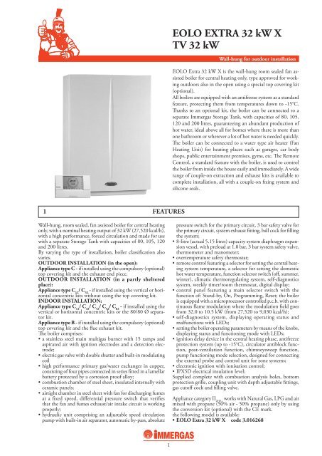
<strong>EOLO</strong> <strong>EXTRA</strong> <strong>32</strong> <strong>kW</strong> X<br />
<strong>TV</strong> <strong>32</strong> <strong>kW</strong><br />
Wall-hung for outdoor installation<br />
<strong>EOLO</strong> Extra <strong>32</strong> <strong>kW</strong> X is the wall-hung room sealed fan assisted<br />
boiler for central heating only, type approved for working<br />
outdoors also in the open using a special top covering kit<br />
(optional).<br />
All boilers are equipped with an antifreeze system as a standard<br />
feature, protecting them from temperatures down to -15°C.<br />
Thanks to an optional kit, the boiler can be connected to a<br />
separate <strong>Immergas</strong> Storage Tank, with capacities of 80, 105,<br />
120 and 200 litres, guaranteeing an abundant production of<br />
hot water, ideal above all for homes where there is more than<br />
one bathroom or wherever a lot of hot water is needed quickly.<br />
The boiler can be connected to a water type air heater (Fan<br />
Heating Unit) for heating places such as garages, car body<br />
shops, public entertainment premises, gyms, etc. The Remote<br />
Control, a standard feature with the boiler, is used to control<br />
the boiler from inside the house easily and immediately. A wide<br />
range of couple-on extraction and exhaust kits is available to<br />
complete installation, all with a couple-on fixing system and<br />
silicone seals.<br />
pressure switch for the primary circuit, 3 bar safety valve for<br />
the primary circuit, system exhaust fitting, ball cock for filling<br />
the system;<br />
• 8-litre (actual 5.15 litres) capacity system diaphragm expansion<br />
vessel, with preload at 1.0 bar, 3 bar system safety valve,<br />
thermometer and manometer;<br />
• overtemperature safety thermostat;<br />
• remote control featuring a selector for setting the central heating<br />
system temperature, a selector for setting the domestic<br />
hot water temperature, function selector switch (off, summer,<br />
winter), climatic thermoregulating system, self-diagnostics<br />
system, weekly timer/room thermostat, digital display;<br />
• control panel featuring a main selector switch with the<br />
function of: Stand-by, On, Programming, Reset; the boiler<br />
is equipped with a microprocessor controlled p.c.b. with continuous<br />
flame modulation where the modulation field goes<br />
from <strong>32</strong>.0 to 10.5 <strong>kW</strong> (from 27,520 to 9,030 kcal/h);<br />
• self-diagnostics system, displaying operating status and<br />
malfunctions with LEDs;<br />
• setting the boiler operating parameters by means of the knobs,<br />
displaying status and functioning mode with LEDs;<br />
• ignition delay device in the central heating phase, antifreeze<br />
protection system (up to -15°C), circulator antiblock function,<br />
post-ventilation function, chimneysweep function,<br />
pump functioning mode selection, designed for connecting<br />
the external probe and control unit for zone systems;<br />
• electronic ignition with ionisation control;<br />
• IPX5D electrical insulation level;<br />
Supplied complete with combustion analysis holes, bottom<br />
protection grille, coupling unit with depth adjustable fittings,<br />
gas cutoff cock and filling valve.<br />
Appliance category II 2H3+ works with Natural Gas, LPG and air<br />
mixed with propane (50% air - 50% propane) only by using<br />
the conversion kit (optional) with the CE mark.<br />
the following model is available:<br />
• <strong>EOLO</strong> Extra <strong>32</strong> <strong>kW</strong> X code 3.016268
2<br />
<strong>EOLO</strong> <strong>EXTRA</strong> <strong>32</strong> <strong>kW</strong> X<br />
<strong>TV</strong> <strong>32</strong> <strong>kW</strong><br />
2 <strong>EOLO</strong> <strong>EXTRA</strong> <strong>32</strong> KW X MAIN COMPONENTS<br />
LEGEND:<br />
1 - Gas valve<br />
2 - System pressure switch<br />
3 - Burner<br />
4 - Combustion chamber<br />
5 - Airtight chamber<br />
6 - Fan<br />
7 - Testing hole (air A) - (fumes F)<br />
8 - Pressure point with positive signal<br />
9 - Pressure point with negative signal<br />
10 - Flue pressure switch<br />
11 - Delivery probe<br />
12 - Safety thermostat<br />
13 - Draught diverter<br />
14 - Primary exchanger<br />
15 - Ignition and detection electrodes<br />
16 - System expansion vessel<br />
17 - Automatic air vent<br />
18 - Boiler circulator<br />
19 - 3-bar safety valve<br />
20 - Automatic by-pass<br />
21 - 3-way valve<br />
22 - Draining cock<br />
23 - Filling valve
3<br />
<strong>EOLO</strong> <strong>EXTRA</strong> <strong>32</strong> <strong>kW</strong> X<br />
<strong>TV</strong> <strong>32</strong> <strong>kW</strong><br />
3 <strong>EOLO</strong> <strong>EXTRA</strong> <strong>32</strong> KW X MAIN DIMENSIONS<br />
Model<br />
<strong>EOLO</strong> <strong>EXTRA</strong> <strong>32</strong> <strong>kW</strong> X<br />
3.1 CONNECTIONS<br />
Model<br />
B<br />
<strong>EOLO</strong> <strong>EXTRA</strong> <strong>32</strong> <strong>kW</strong> X<br />
Height mm<br />
775<br />
A B<br />
Storage Unit Capacity Height Width Depth<br />
UB 80 (80 litres) 850 mm 500 mm 500 mm<br />
UB 105 (105 litres) 1020 mm 500 mm 500 mm<br />
UB 120 (120 litres) 850 mm 600 mm 600 mm<br />
UB 200 (200 litres) 1250 mm 600 mm 600 mm<br />
Delivery<br />
M<br />
3/4"<br />
Return<br />
R<br />
3/4"<br />
Width mm<br />
520<br />
A = extraction/exhaust<br />
B = intake<br />
Distance between the upper casing line and<br />
axis of the concentric 60/100 Ø bend: 95 mm<br />
Distance between the upper casing line and axis<br />
of the 80/80 Ø separator bends: A=135 mm B = 115<br />
System filling<br />
RR<br />
1/2"<br />
Depth mm<br />
250<br />
Gas<br />
G<br />
1/2"<br />
Ø extr./exhaust mm<br />
100/60<br />
Upper casing line<br />
Expansion vessel<br />
Litres<br />
8 (actual 5.15)
4 REMOTE CONTROL<br />
4.1 FEATURES<br />
Two wires (with a minimum cross section of 0.50 mm 2 and<br />
max. 2.5 mm 2 ) are used for connecting to the boiler, maximum<br />
50 metres in length.<br />
The Remote Control is divided into two completely separate<br />
sectors:<br />
• SECTOR FOR SETTING THE TEMPEATURES AND<br />
BOILER FUNCTIONING MODES.<br />
Possibility of working in the antifreeze position: with the<br />
knob on 0 the remote control enables boiler ignition only<br />
when room temperature drops below +5°C (OFF appears<br />
on the display if the room probe is not disabled).<br />
Summer position: the regulator enables the d.h.w. function.<br />
The temperature is set with the knob and shown on<br />
the display while it is being set.<br />
Winter position: the regulator enables operation in both the<br />
d.h.w. and central heating circuits. The temperatures wanted<br />
can be set with the knobs and are shown on the display while<br />
they are being set.<br />
• SECTOR FOR PROGRAMMING THE TIMES AND<br />
ROOM TEMPERATURE.<br />
Manual operation: it works in a range between 5°C and<br />
30°C.<br />
Automatic operation: 2 different control levels (comfort<br />
and reduced) can be set in the day and in the week.<br />
4<br />
<strong>EOLO</strong> <strong>EXTRA</strong> <strong>32</strong> <strong>kW</strong> X<br />
<strong>TV</strong> <strong>32</strong> <strong>kW</strong><br />
The Remote Control is used to remotely control and programme<br />
boiler operation.<br />
It has been designed to guarantee ideal temperature conditions<br />
all night and day each day of the week. The main features that<br />
distinguish the <strong>Immergas</strong> Remote Control are the simplicity<br />
and clarity of the controls and how easy it is to connect it to the<br />
boiler’s electrical control panel. With just two wires, it receives<br />
electricity and sends control and adjustment commands.<br />
Automatic operation with a set programme: the Remote<br />
Control has a “standard” weekly programmed already<br />
stored.<br />
Diagnostics: the Remote Control controls boiler status<br />
continuously and signals any malfunctions giving the corresponding<br />
error code on the display.<br />
The delivery temperature, set room temperature and outdoor<br />
temperature can be seen on the display if the external probe<br />
is connected.<br />
Additional functions: the Remote Control is set so the<br />
indoor room temperature probe can be excluded.<br />
The remote control can work with ON-OFF or Modulating<br />
adjustment. The appliance is supplied set for modulating<br />
operation which can be excluded by changing over to the<br />
ON-OFF mode.<br />
Boiler with external probe: the boiler’s electronic card is set<br />
for using the external probe.<br />
By turning the heating adjustment selector you can set the<br />
ratio between the outdoor temperature and the heating water<br />
temperature according to nine set curves.<br />
A number between 0 and 9 appears on the display which<br />
indicates the curve selected.
5 REMOTE CONTROL - DIMENSIONS<br />
5.1 TECHNICAL DATA<br />
5<br />
<strong>EOLO</strong> <strong>EXTRA</strong> <strong>32</strong> <strong>kW</strong> X<br />
<strong>TV</strong> <strong>32</strong> <strong>kW</strong><br />
• Connection to the boiler with 2 polarised wires<br />
• Possibility of connecting to a telephone control unit<br />
• Graphic display : ................................................................................................................................. LCD<br />
• Dimensions (mm) : ............................................................................................................................. 128 x 82 x 31<br />
• Correct room probe operating range : ................................................................................................. +0 / +40°C<br />
• Reduced temperature setting range : ................................................................................................... +5°C / +25°C<br />
• Comfort temperature setting range : ................................................................................................... +5°C / +30°C<br />
• Room antifreeze intervention temperature : ........................................................................................ +5°C<br />
• Room antifreeze intervention end temperature : ................................................................................. +5.6°C<br />
• Boiler temperature thermostat intervention temperature ON (modulating) : ..................................... set point<br />
• Boiler temperature thermostat intervention temperature OFF (modulating) : .................................... set point +0.6°C<br />
• Boiler temperature thermostat intervention temperature ON (On - O.) : .......................................... set point<br />
• Boiler temperature thermostat intervention temperature OFF (On - O.) : ......................................... set point +0.3°C<br />
• Resolution displayed : ......................................................................................................................... 0.1 °C<br />
• Hourly programmer charge reserve time : ........................................................................................... 8 hours<br />
• Timer programming resolution : ......................................................................................................... 30 minutes<br />
• Maximum number of daily ignitions and switchings off : ................................................................... 48<br />
• Number of standard programmes : ..................................................................................................... 1
6 PUMP FLOW-RATE GRAPH<br />
The boilers of the “<strong>EOLO</strong> <strong>EXTRA</strong> <strong>32</strong> <strong>kW</strong> X” series are<br />
supplied with a built-in circulator with a 3-position electric<br />
speed adjuster. The circulator is already equipped with a<br />
condenser.<br />
6.1 <strong>EOLO</strong> <strong>EXTRA</strong> <strong>32</strong> KW X CIRCULATOR<br />
Available head (kPa)<br />
GRUNDFOS UPS 15-70 AO HB<br />
D B<br />
A: Head available to the system on maximum speed with the by-pass off.<br />
B: Head available to the system on maximum speed with the by-pass on.<br />
C: Head available to the system at second speed with the by-pass off.<br />
D: Head available to the system at second speed with the by-pass on.<br />
C<br />
6<br />
<strong>EOLO</strong> <strong>EXTRA</strong> <strong>32</strong> <strong>kW</strong> X<br />
<strong>TV</strong> <strong>32</strong> <strong>kW</strong><br />
The boilers of the “<strong>EOLO</strong> <strong>EXTRA</strong> <strong>32</strong> <strong>kW</strong> X” series are supplied<br />
with an automatic by-pass which can be excluded by<br />
turning the screw on the front of the hydraulic power unit.<br />
A<br />
Flow-rate l/h<br />
Available head (m H 2 O)
LEGEND:<br />
A5 - CAR interface board<br />
B1 - Delivery probe<br />
B2 - D.h.w. probe (optional)<br />
B4 - External probe (optional)<br />
CAR - Remote control<br />
E1 - Ignition electrodes<br />
E2 - Detection electrode<br />
E4 - Safety thermostat<br />
F1 - Line fuse<br />
F2 - Neutral fuse<br />
M1 - Boiler circulator<br />
M20 - Fan<br />
M30 - 3-way valve (optional)<br />
R5 - D.h.w. temperature trimmer<br />
7<br />
<strong>EOLO</strong> <strong>EXTRA</strong> <strong>32</strong> <strong>kW</strong> X<br />
<strong>TV</strong> <strong>32</strong> <strong>kW</strong><br />
7 <strong>EOLO</strong> <strong>EXTRA</strong> <strong>32</strong> KW X WIRING DIAGRAM<br />
ROOM THERMOSTAT OR REMOTE CONTROL<br />
The remote control (CAR) must be connected to terminals 42<br />
and 43 of connector X2 on the integrated electronic board,<br />
observing polarity.<br />
<br />
<br />
<br />
<br />
<br />
<br />
<br />
<br />
<br />
<br />
<br />
<br />
<br />
<br />
If there is an external probe (B4) is has to be connected to<br />
terminals 38 and 39 of connector X2 on the integrated electronic<br />
board.<br />
<br />
<br />
<br />
<br />
<br />
<br />
<br />
<br />
<br />
<br />
<br />
<br />
<br />
<br />
<br />
<br />
<br />
<br />
R6 - Central heating trimmer<br />
R8 - Storage tank function inhibition heating<br />
element<br />
R10 - Main selector switch<br />
S5 - System pressure switch<br />
S6 - Flue pressure switch<br />
S8 - Gas type selector switch<br />
T1 - Ignition transformer<br />
Y1 - Gas valve<br />
Y2 - Gas valve modulator
LEGEND:<br />
1 - Gas valve<br />
2 - Burner<br />
3 - Primary exchanger<br />
4 - Draught diverter<br />
5 - Fan<br />
6 - Airtight chamber<br />
7 - Flue pressure switch<br />
8 - Delivery probe<br />
9 - Safety thermostat<br />
8<br />
<strong>EOLO</strong> <strong>EXTRA</strong> <strong>32</strong> <strong>kW</strong> X<br />
<strong>TV</strong> <strong>32</strong> <strong>kW</strong><br />
8 <strong>EOLO</strong> <strong>EXTRA</strong> <strong>32</strong> KW X HYDRAULIC DIAGRAM<br />
10 - System expansion vessel<br />
11 - Automatic air vent<br />
12 - Boiler circulator<br />
13 - System pressure switch<br />
14 - 3-way valve<br />
15 - Automatic by-pass<br />
16 - Draining cock<br />
17 - 3 bar safety valve<br />
18 - Filling valve
9<br />
<strong>EOLO</strong> <strong>EXTRA</strong> <strong>32</strong> <strong>kW</strong> X<br />
<strong>TV</strong> <strong>32</strong> <strong>kW</strong><br />
9 <strong>EOLO</strong> <strong>EXTRA</strong> <strong>32</strong> KW X TECHNICAL DATA<br />
Maximum nominal heat input <strong>kW</strong> (kcal/h) 34.3 (29,528))<br />
Maximum useful nominal heat output <strong>kW</strong> (kcal/h) <strong>32</strong>.0 (27,520)<br />
Minimum nominal heat output <strong>kW</strong> (kcal/h) 14,3 (12,336)<br />
Minimum useful nominal output <strong>kW</strong> (kcal/h) 10.5 (9,030)<br />
Efficiency at 100% Pn % 93.20<br />
Efficiency at 30% of load % 91.65<br />
Central heating circuit<br />
Adjusting heating temperature °C 38 - 85<br />
Max. system working temperature °C 90<br />
<strong>EOLO</strong> <strong>EXTRA</strong> <strong>32</strong> X<br />
Max. system working pressure 3 bar<br />
Nominal system expansion vessel capacity / (actual) litres 5.13 / (2.85)<br />
System expansion vessel preload pressure bar 1.0<br />
Available head with a flow rate of 1,000 l/h<br />
D.h.w. circuit (coupled with a Storage Tank)<br />
kPa (m H O) 2 39.02 (3.98)<br />
D.h.w. useful thermal power <strong>kW</strong> (kcal/h) 34.3 (29,528)<br />
Flow rate for 10 min. (∆t 30°C) ST 80 litres litres/min 22.0<br />
Flow rate for 10 min. (∆t 30°C) ST 105 litres litres/min 25.0<br />
Flow rate for 10 min. (∆t 30°C) ST 120 litres litres/min 27.8<br />
Flow rate for 10 min. (∆t 30°C) ST 200 litres litres/min 36.6<br />
Flow rate in continuous service with ST (∆t 30°C)<br />
Gas supply<br />
litres/min 15.3<br />
NATURAL GAS (G20) MIN - MAX mbar 1.50 - 11.50<br />
nozzles n°- ø mm 15 x 1.35<br />
LPG (G30) MIN - MAX mbar 3.70 - 28.00<br />
nozzles n°- ø mm 15 x 0.79<br />
LPG (G31) MIN - MAX mbar 5.00 - 36.00<br />
nozzles n°- ø mm 15 x 0.79<br />
Supply V/Hz 230 - 50<br />
Nominal power draw A 0.97<br />
Electric power installed W 180<br />
Fan power draw W 52<br />
Circulator power draw W 107<br />
Electric insulation level IP X5D<br />
Boiler water capacity litres 2.3<br />
Empty boiler weight kg 41<br />
Energy efficiency marking (EEC directive 92/42) stars ´´´
Gas flow rates refer to the NHV at 15°C and with a 1013 mbar pressure.<br />
The fumes temperature values refer to a 15°C inlet air temperature.<br />
10<br />
<strong>EOLO</strong> <strong>EXTRA</strong> <strong>32</strong> <strong>kW</strong> X<br />
<strong>TV</strong> <strong>32</strong> <strong>kW</strong><br />
10 <strong>EOLO</strong> <strong>EXTRA</strong> <strong>32</strong> KW X COMBUSTION CHARACTERISTICS<br />
Natural gas<br />
(G20)<br />
LPG (G30) LPG (G31)<br />
Combustion efficiency 100% Pn % 93.6 93.6 93.6<br />
Combustion efficiency P min % 87.7 87.7 87.7<br />
Stack losses with burner on (100% Pn) % 6.4 6.4 6.4<br />
Stack losses with burner on (P min) % 11.4 11.4 11.4<br />
Stack losses with burner off % 0.01 0.01 0.01<br />
Outer casing losses with burner off % 0.45 0.45 0.45<br />
Outer casing losses with burner on (100% Pn) % 0.40 0.40 0.40<br />
Outer casing losses with burner on (P min) % 1.5 1.5 1.5<br />
Exhaust flue temperature maximum heat input °C 118 114 112<br />
Exhaust flue temperature minimum heat input °C 95 96 98<br />
Fumes flow rate at maximum heat input kg/h 68 72 73<br />
Fumes flow rate at minimum heat input kg/h 73 73 72<br />
CO 2 at maximum heat input % 7.3 7.9 7.7<br />
CO 2 at minimum heat input % 2.7 3.1 3.1<br />
CO at maximum heat input mg/<strong>kW</strong>h 48 42 34<br />
CO at minimum heat input mg/<strong>kW</strong>h 71 95 83<br />
NO x at maximum heat input mg/<strong>kW</strong>h 409 606 633<br />
NO x at minimum heat input mg/<strong>kW</strong>h 303 301 290<br />
CO weighted mg/<strong>kW</strong>h 63 - -<br />
NO x weighted mg/<strong>kW</strong>h 164 - -<br />
NO x - class - 2 2 2
11<br />
<strong>EOLO</strong> <strong>EXTRA</strong> <strong>32</strong> <strong>kW</strong> X<br />
<strong>TV</strong> <strong>32</strong> <strong>kW</strong><br />
11 OPTIONAL FEATURES FOR <strong>EOLO</strong> <strong>EXTRA</strong> <strong>32</strong> KW X<br />
Telephone control<br />
code 3.013305<br />
Control unit kit for zone systems<br />
code 3.011668<br />
External Storage Tank coupling kit<br />
code 3.016196<br />
Shutoff cock kit with filter<br />
code 3.015854<br />
Cover kit<br />
code 3.016022<br />
External probe<br />
code 3.014083<br />
Configurable relay interface kit<br />
code 3.015350<br />
Additional system expansion vessel kit (2 litres)<br />
code 3.016224<br />
Shutoff cock kit<br />
code 3.5<strong>32</strong>4<br />
The boiler can be coupled to the DIM<br />
(Multi-system Distribution Manifold)<br />
available in 4 recessed kits)
12<br />
<strong>EOLO</strong> <strong>EXTRA</strong> <strong>32</strong> <strong>kW</strong> X<br />
<strong>TV</strong> <strong>32</strong> <strong>kW</strong><br />
<strong>TV</strong> <strong>32</strong> KW FAN HEATING UNIT<br />
12 <strong>TV</strong> <strong>32</strong> KW MAIN FEATURES<br />
The <strong>TV</strong> <strong>32</strong> <strong>kW</strong> fan heating unit consists of:<br />
• a prevarnished steel sheet casing with ABS corners, internally<br />
insulated to prevent the formation of condensation on the<br />
unit when working with chilled water;<br />
• adjustable aluminium deflector fins (spring operated) on the<br />
air delivery for optimum distribution of the air inside the air<br />
conditioned room;<br />
• brackets for fixing the supporting templates (available as an<br />
optional);<br />
• heat exchange battery consisting of copper pipes and aluminium<br />
fins with high thermal conductivity;<br />
• galvanised steel sheet condensation collection tank, insulated<br />
with closed cell polyurethane, connected to an auxiliary<br />
tank;<br />
• single-phase 230 V 3-speed electric motors (1400, 900 and<br />
700 rpm) with internal heat protection (clicson), class F<br />
winding, with IP 55 protection level;<br />
In its range of products <strong>Immergas</strong> proposes a water type air<br />
heater to use with the <strong>EOLO</strong> Extra <strong>32</strong> <strong>kW</strong> boiler thanks to<br />
which garages, car body shops, painting shops, carpenters,<br />
public entertainment premises, gyms, etc., can be heated.<br />
The boiler, placed outdoors for example, heats the convector<br />
fluid which, by way of the boiler circulator and connecting<br />
pipes, is sent to the air heater, equipped with a heat exchanger<br />
and high air flow rate fans that heat the rooms quickly.<br />
The <strong>TV</strong> <strong>32</strong> <strong>kW</strong> fan heating unit is distinguished by its rounded<br />
design, its technical features (3-speed standard motor, set for<br />
working with chilled water) and low noise operation.<br />
One of the <strong>TV</strong> <strong>32</strong> <strong>kW</strong> fan heating unit’s standard features is<br />
its microprocessor control panel (MICROPRO D) used to<br />
control the unit automatically, set and vary fan speed (manual<br />
or automatic), set room temperature and switch from the heating<br />
to the cooling mode.<br />
• axial fan with crescent-shaped blades, statically balanced to<br />
minimise noise;<br />
• accident prevention grille in electrogalvanised steel wire<br />
that supports the motor and is fixed to the unit by means of<br />
vibration proof supports;<br />
• microprocessor control panel (MICROPRO D), featuring<br />
a speed selector switch, electronic thermostat and seasonal<br />
selector switch; with this panel you can set and alter fan speed<br />
(manual or automatic), set room temperature and switch<br />
from the heating to cooling mode;<br />
• power board for connection of the MICROPRO D control<br />
panel;<br />
• electronic water temperature measuring probe for the MI-<br />
CROPRO D control panel.<br />
the following model is available:<br />
• <strong>TV</strong> <strong>32</strong> <strong>kW</strong> code 3015728
13 <strong>TV</strong> <strong>32</strong> KW MAIN COMPONENTS<br />
3<br />
10<br />
1<br />
11<br />
5<br />
12<br />
LEGEND:<br />
1 - Cover casing: side panel<br />
2 - Cover casing: top/bottom panel<br />
3 - Rear panel/fan nozzle<br />
4 - Finned pack heat exchanger<br />
(heat exchange battery)<br />
5 - Accident prevention grille (fan) motor support<br />
6 - Adjustable deflector fins<br />
2<br />
8<br />
13<br />
<strong>EOLO</strong> <strong>EXTRA</strong> <strong>32</strong> <strong>kW</strong> X<br />
<strong>TV</strong> <strong>32</strong> <strong>kW</strong><br />
9<br />
7<br />
4<br />
7 - Auxiliary condensation collection tank<br />
8 - Main condensation collection tank<br />
9 - Top cover of the heat exchange battery<br />
10 - Air conveyor<br />
11 - Wall/ceiling fixing brackets<br />
12 - Plastic casing closing corner piece<br />
(right and left)<br />
6
14 <strong>TV</strong> <strong>32</strong> KW MAIN DIMENSIONS<br />
Model<br />
<strong>TV</strong> <strong>32</strong> <strong>kW</strong><br />
14.1 CONNECTIONS<br />
38 A<br />
25<br />
A mm<br />
660<br />
B<br />
B mm<br />
530<br />
C mm<br />
525<br />
G<br />
A<br />
D mm<br />
528<br />
14<br />
<strong>EOLO</strong> <strong>EXTRA</strong> <strong>32</strong> <strong>kW</strong> X<br />
<strong>TV</strong> <strong>32</strong> <strong>kW</strong><br />
80 E<br />
80<br />
E mm<br />
500<br />
G mm<br />
580<br />
Condensate<br />
C<br />
141<br />
Ø 1<br />
1" M<br />
150<br />
206<br />
300<br />
2<br />
OUT<br />
3<br />
Out<br />
IN<br />
1<br />
Ø 2<br />
1" M<br />
In<br />
31<br />
Ø 3 mm<br />
17<br />
66 D<br />
66
15<br />
<strong>EOLO</strong> <strong>EXTRA</strong> <strong>32</strong> <strong>kW</strong> X<br />
<strong>TV</strong> <strong>32</strong> <strong>kW</strong><br />
15 INSTALLATION HEIGHTS OF THE <strong>TV</strong> <strong>32</strong> KW, WALL MOUNTED<br />
LEGEND:<br />
4P - 4 poles, 1400 rpm<br />
6P - 6 poles, 900 rpm<br />
8P - 8 poles, 700 rpm<br />
Hv - Maximum installation height<br />
Ao - Blast<br />
Bo - Floor area hit by the air<br />
Hv<br />
m<br />
Bo<br />
Ao<br />
Ao<br />
4p (1400 rpm) 6p (900 rpm) 8p (700 rpm)<br />
Ao<br />
m<br />
Bo<br />
m<br />
Hv<br />
m<br />
Ao<br />
m<br />
Bo<br />
m<br />
Hv<br />
NOTE:<br />
Installation ideal for working in both the heating<br />
and cooling mode<br />
<strong>TV</strong> <strong>32</strong> <strong>kW</strong> 4.5 15.0 8.0 4.0 9.0 6.0 3.5 7.5 5.0<br />
Hv<br />
m<br />
Ao<br />
m<br />
Bo<br />
m
16<br />
<strong>EOLO</strong> <strong>EXTRA</strong> <strong>32</strong> <strong>kW</strong> X<br />
<strong>TV</strong> <strong>32</strong> <strong>kW</strong><br />
16 INSTALLATION HEIGHTS OF THE <strong>TV</strong> <strong>32</strong> KW, CEILING MOUNTED<br />
LEGEND:<br />
4P - 4 poles, 1400 rpm<br />
6P - 6 poles, 900 rpm<br />
8P - 8 poles, 700 rpm<br />
Ho - Maximum installation height<br />
Ao - Floor area hit by the air<br />
Bo - Floor area hit by the air<br />
Ho<br />
m<br />
Ao<br />
4p (1400 rpm) 6p (900 rpm) 8p (700 rpm)<br />
Ao<br />
m<br />
Bo<br />
m<br />
Ho<br />
m<br />
Ao<br />
m<br />
Bo<br />
m<br />
Ho<br />
Bo<br />
NOTE:<br />
Installation for working only in the heating<br />
mode.<br />
Installation not to be used in the cooling<br />
mode.<br />
<strong>TV</strong> <strong>32</strong> <strong>kW</strong> 5.0 10.5 6.0 4.0 7.5 5.0 3.5 6.5 3.5<br />
Ho<br />
m<br />
Ao<br />
m<br />
Bo<br />
m
17<br />
<strong>EOLO</strong> <strong>EXTRA</strong> <strong>32</strong> <strong>kW</strong> X<br />
<strong>TV</strong> <strong>32</strong> <strong>kW</strong><br />
17 WIRING DIAGRAM FOR CONNECTING THE MICROPROD<br />
<br />
<br />
<br />
<br />
<br />
<br />
<br />
<br />
<br />
<br />
17.1 WIRING DIAGRAM FOR CONNECTING THE MICROPROD TO THE BOILER<br />
<br />
<br />
<br />
LEGEND:<br />
SA - Room probe<br />
SW - Water temperature probe<br />
<br />
<br />
<br />
<br />
<br />
<br />
<br />
<br />
LEGEND:<br />
P1 - Central heating timer (optional)<br />
K5 - Interface relay TA (230V)<br />
(not supplied)<br />
SA - Room probe<br />
SW - Water temperature probe
18<br />
<strong>EOLO</strong> <strong>EXTRA</strong> <strong>32</strong> <strong>kW</strong> X<br />
<strong>TV</strong> <strong>32</strong> <strong>kW</strong><br />
18 <strong>TV</strong> <strong>32</strong> KW FAN HEATING UNIT TECHNICAL DATA<br />
18.1 NOMINAL TECHNICAL FEATURES, <strong>TV</strong> <strong>32</strong> KW<br />
Model Fan speed Air flow<br />
rate<br />
m 3 /h<br />
<strong>TV</strong> <strong>32</strong> <strong>kW</strong><br />
4P<br />
6P<br />
8P<br />
4463<br />
2835<br />
2231<br />
Heating<br />
output<br />
<strong>kW</strong><br />
37.83<br />
28.72<br />
24.69<br />
Note: Performance refers to the following conditions.<br />
Cooling:<br />
Water temperature 7/12°C, air temperature 28°C with dry<br />
bulb, 55% relative humidity<br />
Heating:<br />
Water temperature 85/75°C, air temperature 20°C<br />
Fan speed:<br />
4 p= 4 poles, 1400 rpm<br />
6 p= 6 poles, 900 rpm<br />
8 p= 8 poles, 700 rpm<br />
Total<br />
cooling<br />
<strong>kW</strong><br />
-<br />
12.56<br />
10.71<br />
Significant<br />
cooling<br />
<strong>kW</strong><br />
-<br />
7.45<br />
6.39<br />
18.2 DOSAGE OF ANTIFREEZE GLYCOLS, <strong>TV</strong> <strong>32</strong> KW<br />
Max. installation<br />
height<br />
m<br />
4.5<br />
4.0<br />
3.5<br />
Sound<br />
power<br />
dB A<br />
Percentage of glycols in weight Freezing temperature (°C) Variation of power output Head loss variation<br />
0 0 1.00 1.00<br />
10 -4 0.97 1.05<br />
20 -10 0.92 1.10<br />
30 -16 0.87 1.15<br />
40 -24 0.82 1.20<br />
Attention:<br />
If the boiler is installed outdoors or on premises where<br />
temperatures can go below O°C, we recommend putting<br />
some antifreeze glycols in the system to avoid the circuit<br />
freezing.<br />
See the following table for the percentages of antifreeze<br />
glycols to use.<br />
74<br />
65<br />
59<br />
Weight<br />
kg<br />
34.5
18.3 <strong>TV</strong> <strong>32</strong> KW HEATING OUTPUT<br />
Legend:<br />
∆pw Head loss on water side<br />
PT Central heating potential<br />
Qw Water flow-rate<br />
Tbs1 Dry bulb temperature of inlet air<br />
Temperature of outlet air<br />
Tbs 2<br />
Tw 1 / Tw 2<br />
19<br />
<strong>EOLO</strong> <strong>EXTRA</strong> <strong>32</strong> <strong>kW</strong> X<br />
<strong>TV</strong> <strong>32</strong> <strong>kW</strong><br />
45°C / 40°C<br />
Tbs 1 0°C 10°C 15°C 20°C<br />
Vr<br />
<strong>TV</strong> <strong>32</strong> <strong>kW</strong> 4P<br />
<strong>TV</strong> <strong>32</strong> <strong>kW</strong> 6P<br />
<strong>TV</strong> <strong>32</strong> <strong>kW</strong> 8P<br />
Tw 1 / Tw 2<br />
PT<br />
<strong>kW</strong><br />
27.10<br />
20.64<br />
17.78<br />
Qw<br />
l/h<br />
4713<br />
3589<br />
3091<br />
∆pw<br />
kPa<br />
34<br />
21<br />
16<br />
Tbs 2<br />
°C<br />
16.8<br />
20.2<br />
22.1<br />
PT<br />
<strong>kW</strong><br />
20.24<br />
15.41<br />
13.27<br />
Qw<br />
l/h<br />
3519<br />
2680<br />
2308<br />
∆pw<br />
kPa<br />
20<br />
13<br />
10<br />
Tw Water inlet temperature<br />
1<br />
Tw Water outlet temperature<br />
2<br />
Vr Ventilation speed:<br />
4p = 4 poles, 1400 rpm<br />
6p = 6 poles, 900 rpm<br />
8p = 8 poles, 700 rpm<br />
Tbs 2<br />
°C<br />
23.0<br />
25.6<br />
27.1<br />
PT<br />
<strong>kW</strong><br />
16.86<br />
12.84<br />
11.06<br />
70°C / 60°C<br />
Tbs 1 0°C 10°C 15°C 20°C<br />
Vr<br />
<strong>TV</strong> <strong>32</strong> <strong>kW</strong> 4P<br />
<strong>TV</strong> <strong>32</strong> <strong>kW</strong> 6P<br />
<strong>TV</strong> <strong>32</strong> <strong>kW</strong> 8P<br />
Tw 1 / Tw 2<br />
PT<br />
<strong>kW</strong><br />
41.52<br />
31.64<br />
27.27<br />
Qw<br />
l/h<br />
3642<br />
2775<br />
2391<br />
∆pw<br />
kPa<br />
20<br />
12<br />
9<br />
Tbs 2<br />
°C<br />
25.8<br />
30.9<br />
33.8<br />
PT<br />
<strong>kW</strong><br />
34.52<br />
26.29<br />
22.65<br />
Qw<br />
l/h<br />
3030<br />
2307<br />
1986<br />
∆pw<br />
kPa<br />
14<br />
9<br />
7<br />
Tbs 2<br />
°C<br />
<strong>32</strong>.2<br />
36.6<br />
39.1<br />
PT<br />
<strong>kW</strong><br />
31.08<br />
23.67<br />
20.38<br />
80°C / 65°C<br />
Tbs 1 0°C 10°C 15°C 20°C<br />
Vr<br />
<strong>TV</strong> <strong>32</strong> <strong>kW</strong> 4P<br />
<strong>TV</strong> <strong>32</strong> <strong>kW</strong> 6P<br />
<strong>TV</strong> <strong>32</strong> <strong>kW</strong> 8P<br />
PT<br />
<strong>kW</strong><br />
45.75<br />
34.94<br />
30.14<br />
Qw<br />
l/h<br />
2684<br />
2049<br />
1768<br />
∆pw<br />
kPa<br />
11<br />
7<br />
5<br />
Tbs 2<br />
°C<br />
28.4<br />
34.1<br />
37.4<br />
PT<br />
<strong>kW</strong><br />
38.73<br />
29.56<br />
25.49<br />
Qw<br />
l/h<br />
2273<br />
1735<br />
1496<br />
∆pw<br />
kPa<br />
8<br />
5<br />
4<br />
Tbs 2<br />
°C<br />
34.9<br />
39.9<br />
42.8<br />
PT<br />
<strong>kW</strong><br />
35.26<br />
26.92<br />
23.21<br />
Qw<br />
l/h<br />
29<strong>32</strong><br />
2234<br />
1924<br />
Qw<br />
l/h<br />
2726<br />
2076<br />
1789<br />
Qw<br />
l/h<br />
2070<br />
1579<br />
1362<br />
∆pw<br />
kPa<br />
15<br />
9<br />
7<br />
∆pw<br />
kPa<br />
12<br />
7<br />
6<br />
∆pw<br />
kPa<br />
7<br />
4<br />
3<br />
Tbs 2<br />
°C<br />
26.0<br />
28.2<br />
29.5<br />
Tbs 2<br />
°C<br />
35.3<br />
39.4<br />
41.7<br />
Tbs 2<br />
°C<br />
38.1<br />
42.7<br />
45.4<br />
PT<br />
<strong>kW</strong><br />
13.51<br />
10.31<br />
8.88<br />
PT<br />
<strong>kW</strong><br />
27.66<br />
21.06<br />
18.14<br />
PT<br />
<strong>kW</strong><br />
31.83<br />
24.30<br />
20.96<br />
Qw<br />
l/h<br />
2349<br />
1792<br />
1545<br />
Qw<br />
l/h<br />
2426<br />
1849<br />
1592<br />
Qw<br />
l/h<br />
1868<br />
1426<br />
1230<br />
∆pw<br />
kPa<br />
10<br />
6<br />
5<br />
∆pw<br />
kPa<br />
10<br />
6<br />
5<br />
∆pw<br />
kPa<br />
6<br />
4<br />
3<br />
Tbs 2<br />
°C<br />
29.0<br />
30.8<br />
31.8<br />
Tbs 2<br />
°C<br />
38.4<br />
42.1<br />
44.2<br />
Tbs 2<br />
°C<br />
41.2<br />
45.5<br />
47.9
18.4 <strong>TV</strong> <strong>32</strong> KW HEATING OUTPUT<br />
Legend:<br />
∆pw Head loss on water side<br />
PT Central heating potential<br />
Qw Water flow-rate<br />
Tbs1 Dry bulb inlet air temperature<br />
Temperature of outlet air<br />
Tbs 2<br />
Tw 1 / Tw 2<br />
20<br />
<strong>EOLO</strong> <strong>EXTRA</strong> <strong>32</strong> <strong>kW</strong> X<br />
<strong>TV</strong> <strong>32</strong> <strong>kW</strong><br />
85°C / 70°C<br />
Tbs 1 0°C 10°C 15°C 20°C<br />
Vr<br />
<strong>TV</strong> <strong>32</strong> <strong>kW</strong> 4P<br />
<strong>TV</strong> <strong>32</strong> <strong>kW</strong> 6P<br />
<strong>TV</strong> <strong>32</strong> <strong>kW</strong> 8P<br />
Tw 1 / Tw 2<br />
PT<br />
<strong>kW</strong><br />
49.24<br />
37.57<br />
<strong>32</strong>.40<br />
Qw<br />
l/h<br />
2894<br />
2209<br />
1906<br />
∆pw<br />
kPa<br />
13<br />
8<br />
6<br />
Tbs 2<br />
°C<br />
30.5<br />
36.7<br />
40.2<br />
PT<br />
<strong>kW</strong><br />
42.18<br />
<strong>32</strong>.17<br />
27.73<br />
Qw<br />
l/h<br />
2480<br />
1891<br />
1630<br />
∆pw<br />
kPa<br />
10<br />
6<br />
5<br />
Tw Water inlet temperature<br />
1<br />
Tw Water outlet temperature<br />
2<br />
Vr Ventilation speed:<br />
4p = 4 poles, 1400 rpm<br />
6p = 6 poles, 900 rpm<br />
8p =8 poles, 700 rpm<br />
Tbs 2<br />
°C<br />
37.1<br />
42.6<br />
45.7<br />
PT<br />
<strong>kW</strong><br />
38.70<br />
29.51<br />
25.43<br />
85°C / 75°C<br />
Tbs 1 0°C 10°C 15°C 20°C<br />
Vr<br />
<strong>TV</strong> <strong>32</strong> <strong>kW</strong> 4P<br />
<strong>TV</strong> <strong>32</strong> <strong>kW</strong> 6P<br />
<strong>TV</strong> <strong>32</strong> <strong>kW</strong> 8P<br />
Tw 1 / Tw 2<br />
PT<br />
<strong>kW</strong><br />
51.90<br />
39.49<br />
33.99<br />
Qw<br />
l/h<br />
4582<br />
3486<br />
3001<br />
∆pw<br />
kPa<br />
28<br />
18<br />
14<br />
Tbs 2<br />
°C<br />
<strong>32</strong>.2<br />
38.6<br />
42.2<br />
PT<br />
<strong>kW</strong><br />
44.80<br />
34.04<br />
29.28<br />
Qw<br />
l/h<br />
3955<br />
3006<br />
2585<br />
∆pw<br />
kPa<br />
22<br />
14<br />
10<br />
Tbs 2<br />
°C<br />
38.8<br />
44.5<br />
47.7<br />
PT<br />
<strong>kW</strong><br />
41.30<br />
31.37<br />
26.97<br />
90°C / 70°C<br />
Tbs 1 0°C 10°C 15°C 20°C<br />
Vr<br />
<strong>TV</strong> <strong>32</strong> <strong>kW</strong> 4P<br />
<strong>TV</strong> <strong>32</strong> <strong>kW</strong> 6P<br />
<strong>TV</strong> <strong>32</strong> <strong>kW</strong> 8P<br />
PT<br />
<strong>kW</strong><br />
50.08<br />
38.30<br />
33.07<br />
Qw<br />
l/h<br />
2210<br />
1691<br />
1460<br />
∆pw<br />
kPa<br />
8<br />
5<br />
4<br />
Tbs 2<br />
°C<br />
31.1<br />
37.4<br />
41.0<br />
PT<br />
<strong>kW</strong><br />
43.03<br />
<strong>32</strong>.89<br />
28.39<br />
Qw<br />
l/h<br />
1899<br />
1452<br />
1254<br />
∆pw<br />
kPa<br />
6<br />
4<br />
3<br />
Tbs 2<br />
°C<br />
37.7<br />
43.3<br />
46.5<br />
PT<br />
<strong>kW</strong><br />
39.54<br />
30.23<br />
26.09<br />
Qw<br />
l/h<br />
2276<br />
1735<br />
1495<br />
Qw<br />
l/h<br />
3645<br />
2769<br />
2381<br />
Qw<br />
l/h<br />
1746<br />
1334<br />
1152<br />
∆pw<br />
kPa<br />
8<br />
5<br />
4<br />
∆pw<br />
kPa<br />
19<br />
12<br />
9<br />
∆pw<br />
kPa<br />
5<br />
3<br />
3<br />
Tbs 2<br />
°C<br />
40.3<br />
45.4<br />
48.3<br />
Tbs 2<br />
°C<br />
42.0<br />
47.3<br />
50.3<br />
Tbs 2<br />
°C<br />
40.9<br />
46.1<br />
49.2<br />
PT<br />
<strong>kW</strong><br />
35.25<br />
26.88<br />
23.16<br />
PT<br />
<strong>kW</strong><br />
37.83<br />
28.72<br />
24.69<br />
PT<br />
<strong>kW</strong><br />
36.09<br />
27.60<br />
23.82<br />
Qw<br />
l/h<br />
2073<br />
1580<br />
1362<br />
Qw<br />
l/h<br />
3339<br />
2536<br />
2180<br />
Qw<br />
l/h<br />
1594<br />
1218<br />
1052<br />
∆pw<br />
kPa<br />
7<br />
4<br />
3<br />
∆pw<br />
kPa<br />
16<br />
10<br />
8<br />
∆pw<br />
kPa<br />
4<br />
3<br />
2<br />
Tbs 2<br />
°C<br />
43.5<br />
48.2<br />
50.8<br />
Tbs 2<br />
°C<br />
45.2<br />
50.1<br />
52.9<br />
Tbs 2<br />
°C<br />
44.0<br />
48.9<br />
51.7
18.5 <strong>TV</strong> <strong>32</strong> KW COOLING OUTPUT<br />
Legend:<br />
∆pw Head loss on water side<br />
PFS Significant cooling potential<br />
PFT Total cooling potential<br />
Qw Water flow-rate<br />
Tbs1 Dry bulb outlet air temperatureo<br />
Tbs 1 / UR 1 (Tbu 1 ) 27°C / 50% (19°C)<br />
21<br />
<strong>EOLO</strong> <strong>EXTRA</strong> <strong>32</strong> <strong>kW</strong> X<br />
<strong>TV</strong> <strong>32</strong> <strong>kW</strong><br />
Tbu Wet bulb outlet air temperature<br />
1<br />
Tw Water inlet temperature<br />
1<br />
Tw Water outlet temperature<br />
2<br />
Vr Ventilation speed:<br />
6p = 6 poles, 900 rpm<br />
8p = 8 poles, 700 rpm<br />
Tw 1 / Tw 2 7°C / 12°C 9°C / 14°C 10°C / 15°C 11°C / 15°C<br />
<strong>TV</strong> <strong>32</strong> <strong>kW</strong> 6P<br />
<strong>TV</strong> <strong>32</strong> <strong>kW</strong> 8P<br />
Vr PFT<br />
<strong>kW</strong><br />
8.20<br />
6.83<br />
PFS<br />
<strong>kW</strong><br />
6.83<br />
5.78<br />
Qw<br />
l/h<br />
1409<br />
1171<br />
∆pw<br />
kPa<br />
5<br />
4<br />
PFT<br />
<strong>kW</strong><br />
6.02<br />
5.05<br />
PFS<br />
<strong>kW</strong><br />
6.02<br />
5.05<br />
Qw<br />
l/h<br />
1035<br />
868<br />
∆pw<br />
kPa<br />
3<br />
2<br />
PFT<br />
<strong>kW</strong><br />
Tbs 1 / UR 1 (Tbu 1 ) 28°C / 55% (19°C)<br />
Tw 1 / Tw 2 7°C / 12°C 9°C / 14°C 10°C / 15°C 11°C / 15°C<br />
<strong>TV</strong> <strong>32</strong> <strong>kW</strong> 6P<br />
<strong>TV</strong> <strong>32</strong> <strong>kW</strong> 8P<br />
Vr PFT<br />
<strong>kW</strong><br />
12.56<br />
10.71<br />
PFS<br />
<strong>kW</strong><br />
7.45<br />
6.39<br />
Qw<br />
l/h<br />
2191<br />
1875<br />
∆pw<br />
kPa<br />
11<br />
8<br />
PFT<br />
<strong>kW</strong><br />
9.81<br />
8.26<br />
PFS<br />
<strong>kW</strong><br />
6.53<br />
5.50<br />
Attention:<br />
To avoid condensation release phenomena do not use the<br />
<strong>TV</strong> <strong>32</strong> <strong>kW</strong> Fan Heating Unit at the 1,400 rpm speed (4<br />
poles) in the cooling mode.<br />
Qw<br />
l/h<br />
1714<br />
1417<br />
∆pw<br />
kPa<br />
7<br />
5<br />
5.59<br />
4.55<br />
PFT<br />
<strong>kW</strong><br />
8.11<br />
6.93<br />
PFS<br />
<strong>kW</strong><br />
5.59<br />
4.55<br />
PFS<br />
<strong>kW</strong><br />
5.90<br />
5.11<br />
Qw<br />
l/h<br />
961<br />
781<br />
Qw<br />
l/h<br />
1373<br />
1208<br />
∆pw<br />
kPa<br />
2<br />
2<br />
∆pw<br />
kPa<br />
5<br />
4<br />
PFT<br />
<strong>kW</strong><br />
5.82<br />
4.84<br />
PFT<br />
<strong>kW</strong><br />
8.85<br />
7.56<br />
PFS<br />
<strong>kW</strong><br />
5.82<br />
4.84<br />
PFS<br />
<strong>kW</strong><br />
6.15<br />
5.29<br />
Qw<br />
l/h<br />
1250<br />
1040<br />
Qw<br />
l/h<br />
1891<br />
1637<br />
∆pw<br />
kPa<br />
4<br />
3<br />
∆pw<br />
kPa<br />
8<br />
6
18.6 <strong>TV</strong> <strong>32</strong> KW SOUND LEVELS<br />
Legend:<br />
Lp A<br />
<strong>TV</strong> <strong>32</strong> <strong>kW</strong><br />
Global A-weighted sound pressure level calculated<br />
at a distance of 5 metres with a directional<br />
factor of 2.<br />
Lw Sound pressure level for the octave band,<br />
not weighted<br />
Vr<br />
125 Hz<br />
dB<br />
250 Hz<br />
dB<br />
500 Hz<br />
dB<br />
1000 Hz<br />
dB<br />
22<br />
<strong>EOLO</strong> <strong>EXTRA</strong> <strong>32</strong> <strong>kW</strong> X<br />
<strong>TV</strong> <strong>32</strong> <strong>kW</strong><br />
Lw A<br />
Global A-weighted sound pressure level<br />
Vr Ventilation speed:<br />
4p = 4 poles, 1400 rpm<br />
6p = 6 poles, 900 rpm<br />
8p = 8 poles, 700 rpm<br />
Lw<br />
2000 Hz<br />
dB<br />
4000 Hz<br />
dB<br />
8000 Hz<br />
dB<br />
Lw A<br />
dB A<br />
4p 69.9 71.1 69.8 69.3 67.1 64.2 57.6 74 52<br />
6p 65.0 61.5 62.3 59.5 58.2 54.1 46.6 65 43<br />
8p 59.0 55.5 56.3 53.5 52.2 48.1 40.6 59 37<br />
18.7 <strong>TV</strong> <strong>32</strong> KW VENTILATION CHARACTERISTICS<br />
Legend:<br />
Psu Useful static pressure<br />
Vr Ventilation speed:<br />
4p = 4 poles, 1400 rpm<br />
6p = 6 poles, 900 rpm<br />
F Air flow rate variation factor<br />
1<br />
Power output variation factor<br />
F 2<br />
<strong>TV</strong> <strong>32</strong> <strong>kW</strong><br />
Lp A<br />
dB A<br />
The variation factors refer to models without the air delivery<br />
fins.<br />
Multiply the air flow rate by factor F 1 and potential by factor<br />
F 2 .<br />
Psu 10 Pa 20 Pa 30 Pa 40 Pa 50 Pa<br />
Vr F 1 F 2 F 1 F 2 F 1 F 2 F 1 F 2 F 1 F 2<br />
4 p 0.98 0.98 0.93 0.95 0.89 0.93 0.85 0.90 0.77 0.85<br />
6 p 0.89 0.94 0.78 0.88 - - - - - -
23<br />
<strong>EOLO</strong> <strong>EXTRA</strong> <strong>32</strong> <strong>kW</strong> X<br />
<strong>TV</strong> <strong>32</strong> <strong>kW</strong><br />
19 OPTIONAL ACCESSORIES FOR THE <strong>TV</strong> <strong>32</strong> KW FAN UNIT<br />
Wall fixing template kit<br />
code 3.015737<br />
Adjustable wall fixing template kit<br />
code 3.015739<br />
External filling cock kit<br />
code 3.016139<br />
Column fixing template kit<br />
code 3.015738<br />
Connection covering kit<br />
code 3.015658
During their working life,<br />
the performances of the<br />
products are influenced<br />
by external factors such<br />
as the hardness of the domestic<br />
water, the weather<br />
conditions, scaling in the<br />
system, etc. The data indicated<br />
in this brochure<br />
refer to new products,<br />
installed and used in<br />
compliance with the current<br />
standards in force.<br />
NOT E : r e m e m b e r t o<br />
have your appliance per<br />
i o d i c a l l y s e r v i c e d .<br />
42041 Brescello (RE) Italy - Tel. 0522.689011 - Fax 0522.689102<br />
www.immergas.com<br />
<strong>Immergas</strong> reserves the right to make all modifications to the models considered necessary for product development without prior notice.<br />
Code S.0069 rev. 000 - 04/2005 - <strong>Immergas</strong> P.R. Dept. - Arti Grafiche Castello - Viadana (MN)