Aerodynamic calculation of loads and dynamic behavior of wind ...
Aerodynamic calculation of loads and dynamic behavior of wind ...
Aerodynamic calculation of loads and dynamic behavior of wind ...

Create successful ePaper yourself
Turn your PDF publications into a flip-book with our unique Google optimized e-Paper software.
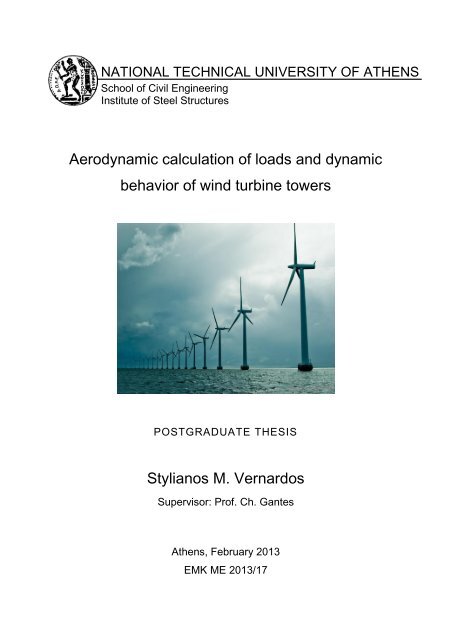
NATIONAL TECHNICAL UNIVERSITY OF ATHENS<br />
School <strong>of</strong> Civil Engineering<br />
Institute <strong>of</strong> Steel Structures<br />
<strong>Aero<strong>dynamic</strong></strong> <strong>calculation</strong> <strong>of</strong> <strong>loads</strong> <strong>and</strong> <strong>dynamic</strong><br />
<strong>behavior</strong> <strong>of</strong> <strong>wind</strong> turbine towers<br />
POSTGRADUATE THESIS<br />
Stylianos M. Vernardos<br />
Supervisor: Pr<strong>of</strong>. Ch. Gantes<br />
Athens, February 2013<br />
ΕΜΚ ΜΕ 2013/17
ΕΘΝΙΚΟ ΜΕΣΟΒΙΟ ΠΟΛΤΣΕΥΝΕΙΟ<br />
τολή Πολιηικών Μητανικών<br />
Εργαζηήριο Μεηαλλικών Καηαζκεσών<br />
Αεροδσναμικός σπολογιζμός θορηίων και<br />
δσναμική ζσμπεριθορά πσλώνων<br />
ανεμογεννηηριών<br />
ΜΕΣΑΠΣΤΥΙΑΚΗ ΕΡΓΑΙΑ<br />
ησλιανός Μ. Βερνάρδος<br />
Επιβλέπων: Υαρ. Γανηές, Καθηγηηής ΕΜΠ<br />
Αθήνα, Φεβροσάριος 2013<br />
ΕΜΚ ΜΕ 2013/17<br />
3
Βεξλάξδνο . M. (2013).<br />
Αεξνδπλακηθόο ππνινγηζκόο θνξηίσλ θαη δπλακηθή ζπκπεξηθνξά ππιώλσλ<br />
αλεκνγελλεηξηώλ<br />
Μεηαπηπρηαθή Δξγαζία ΔΜΚ ΜΔ 2013/17<br />
Δξγαζηήξην Μεηαιιηθώλ Καηαζθεπώλ, Δζληθό Μεηζόβην Πνιπηερλείν, Αζήλα.<br />
Vernardos S. M. (2013).<br />
<strong>Aero<strong>dynamic</strong></strong> <strong>calculation</strong> <strong>of</strong> <strong>loads</strong> <strong>and</strong> <strong>dynamic</strong> <strong>behavior</strong> <strong>of</strong> <strong>wind</strong> turbine towers<br />
Postgraduate Thesis ΔΜΚ ΜΔ 2013/17<br />
Institute <strong>of</strong> Steel Structures, National Technical University <strong>of</strong> Athens, Greece<br />
5
Contents<br />
Πεξίιεςε .......................................................................................................................... 7<br />
Abstract ............................................................................................................................. 8<br />
1 Introduction ......................................................................................................... 10<br />
1.1 General ........................................................................................................ 10<br />
1.2 Thesis’s objective ........................................................................................ 11<br />
2 The <strong>wind</strong> resource ............................................................................................... 13<br />
2.1 Wind variations ........................................................................................... 13<br />
2.2 Turbulence intensity .................................................................................... 14<br />
2.3 The boundary layer properties ..................................................................... 16<br />
2.4 The <strong>wind</strong> velocity as a stochastic process ................................................... 17<br />
2.5 Wind simulation .......................................................................................... 21<br />
3 <strong>Aero<strong>dynamic</strong></strong>s <strong>of</strong> a <strong>wind</strong> turbine ......................................................................... 27<br />
3.1 Actuator disk concept .................................................................................. 27<br />
3.2 Rotor disk theory ......................................................................................... 33<br />
3.3 An abstract definition <strong>of</strong> <strong>loads</strong>’ fundamentals ............................................. 38<br />
3.4 The blade element – momentum (BEM) theory .......................................... 41<br />
3.5 Five significant points concerning B.E.M. .................................................. 44<br />
3.6 An alternative method ................................................................................. 45<br />
3.7 Tower shadow ............................................................................................. 46<br />
4 The algorithm ...................................................................................................... 48<br />
4.1 General ........................................................................................................ 48<br />
4.2 Flow <strong>of</strong> the algorithm .................................................................................. 48<br />
4.3 Accuracy <strong>of</strong> the algorithm ........................................................................... 49<br />
5 Results ................................................................................................................. 53<br />
5.1 The two methods <strong>of</strong> induction factors’ <strong>calculation</strong> ..................................... 53<br />
5.2 Out-<strong>of</strong>-plane <strong>and</strong> in-plane force <strong>calculation</strong> for constant <strong>wind</strong> velocity ..... 54<br />
5.3 Generation <strong>of</strong> <strong>wind</strong> velocity time histories .................................................. 59<br />
5.4 Generation <strong>of</strong> aero<strong>dynamic</strong>-<strong>loads</strong> time histories ......................................... 64<br />
6 Dynamic Analysis ............................................................................................... 67<br />
6.1 General ........................................................................................................ 67<br />
6.2 Tower model ................................................................................................ 67<br />
6.3 Tower loading .............................................................................................. 70<br />
6.3.1 Displacements ....................................................................................... 70<br />
6.3.2 Stresses .................................................................................................. 76<br />
7 Final remarks <strong>and</strong> suggestions for further research ............................................. 85<br />
8 References ........................................................................................................... 86<br />
6
ΔΘΝΙΚΟ ΜΔΣΟΒΙΟ ΠΟΛΤΣΔΥΝΔΙΟ<br />
ΥΟΛΗ ΠΟΛΙΣΙΚΩΝ ΜΗΥΑΝΙΚΩΝ<br />
ΔΡΓΑΣΗΡΙΟ ΜΔΣΑΛΛΙΚΩΝ ΚΑΣΑΚΔΤΩΝ<br />
ΜΔΣΑΠΣΤΥΙΑΚΗ ΔΡΓΑΙΑ<br />
ΔΜΚ MΔ 2013/17<br />
Αεροδσναμικός σπολογιζμός θορηίων και δσναμική ζσμπεριθορά<br />
πσλώνων ανεμογεννηηριών<br />
ηπιηαλόο Βεξλάξδνο<br />
Δπηβιέπσλ: Υάξεο Γαληέο, Καζεγεηήο ΔΜΠ<br />
Περίληψη<br />
ε κία πεξίνδν αλεμέιεγθηεο θαηαλάισζεο ελέξγεηαο, νη αλεκνγελλήηξηεο<br />
δηαδξακαηίδνπλ ην δηθό ηνπο ζεκαληηθό ξόιν, σο αλαπόζπαζην κέινο ηεο επξύηεξεο<br />
νηθνγέλεηαο ησλ ελαιιαθηηθώλ πεγώλ. Η θαηλνκεληθά απιή ηνπο ιεηηνπξγία,<br />
σζηόζν, έξρεηαη ζε πιήξε αληίζεζε κε ηελ πεξίπινθε θύζε ησλ θαηλνκέλσλ ηα<br />
νπνία ζπληεινύληαη από ηελ πξώηε επαθή ηεο κάδαο ηνπ αέξα κε ην κεραληζκό ησλ<br />
πεξηζηξεθόκελσλ πηεξπγίσλ κίαο ηέηνηαο θαηαζθεπήο. Αθξηβώο απηό ην γεγνλόο<br />
δπζρεξαίλεη ζε κεγάιν βαζκό ηελ πξνζνκνίσζε ησλ ζπλζεθώλ ππό ηηο νπνίεο κία<br />
αλεκνγελλήηξηα θαιείηαη, ηόζν λα παξάγεη σθέιηκν έξγν, όζν θαη λα αληεπεμέιζεη<br />
κε αζθάιεηα ζε θάζε είδνπο θνξηίζεηο. Σν εγρείξεκα ηεο αλαπαξαγσγήο απηώλ ησλ<br />
ζπλζεθώλ ζε ππνινγηζηηθό πεξηβάιινλ απνηέιεζε ην ζηόρν ηεο παξνύζαο εξγαζίαο,<br />
αθελόο κέζσ ηεο δεκηνπξγίαο ελόο πεδίνπ αλέκνπ από έλα ζύλνιν ζηνραζηηθώλ<br />
δηαδηθαζηώλ θαη αθεηέξνπ κέζσ ηεο πξνζνκνίσζεο ηεο αεξνδπλακηθήο<br />
ζπκπεξηθνξάο ησλ πηεξπγίσλ αιιά θαη ηνπ ππιώλα. Οη ζρεηηθνί ππνινγηζκνί<br />
πξαγκαηνπνηήζεθαλ ζε πεξηβάιινλ Matlab, κέζσ ηεο παξαγσγήο ελόο αιγνξίζκνπ, ν<br />
νπνίνο, ιακβάλνληαο ππόςε ηηο απαξαίηεηεο, πνηθίιεο παξακέηξνπο πνπ ζρεηίδνληαη<br />
κε ηα αεξνδπλακηθά θαηλόκελα, θαηαιήγεη ζηε δεκηνπξγία ρξνλνïζηνξηώλ θόξηηζεο<br />
ιόγσ αλέκνπ γηα ηνλ ππιώλα ηεο αλεκνγελλήηξηαο. Σα απνηειέζκαηα<br />
ελζσκαηώζεθαλ σο ζπλζήθεο θόξηηζεο ζε έλα κεραληθό πξνζνκνίσκα ππιώλα, ην<br />
νπνίν δεκηνπξγήζεθε κε ηε βνήζεηα ηνπ πξνγξάκκαηνο SAP2000 θαη αλαιύζεθε<br />
δπλακηθά, κε γξακκηθά, ώζηε λα εμεηαζηνύλ νη πξνθύπηνπζεο ρξνλνïζηνξίεο<br />
απνθξίζεσλ θαη ηάζεσλ, θαζώο θαη λα ειεγρζεί ε επάξθεηα ησλ δηαηνκώλ πνπ<br />
επηιέρζεθαλ.<br />
7
NATIONAL TECHNICAL UNIVERSITY OF ATHENS<br />
SCHOOL OF CIVIL ENGINEERING<br />
INSTITUTE OF STEEL STRUCTURES<br />
POSTGRADUATE THESIS<br />
ΔΜΚ ΜΔ 2013/17<br />
<strong>Aero<strong>dynamic</strong></strong> <strong>calculation</strong> <strong>of</strong> <strong>wind</strong> <strong>loads</strong> <strong>and</strong> <strong>dynamic</strong> <strong>behavior</strong> <strong>of</strong><br />
<strong>wind</strong> turbine towers<br />
Stylianos Vernardos<br />
Supervised by Pr<strong>of</strong>. Charis Gantes<br />
Abstract<br />
In an era <strong>of</strong> massive energy consumption, <strong>wind</strong> turbines play their own important role<br />
as an integral part <strong>of</strong> the wider ensemble <strong>of</strong> alternative energy sources. Their<br />
seemingly simple function, however, contradicts the complex nature <strong>of</strong> the<br />
phenomena, occurring from the very first contact between the air mass <strong>and</strong> the<br />
rotating blades’ mechanism <strong>of</strong> such a construction. It is exactly this fact that<br />
significantly hinders the simulation <strong>of</strong> the conditions, under which a <strong>wind</strong> turbine is<br />
expected to produce power <strong>and</strong> also safely withst<strong>and</strong> any kind <strong>of</strong> <strong>loads</strong> exerted on it.<br />
The venture <strong>of</strong> reproducing these conditions in a computational environment<br />
constituted the aim <strong>of</strong> the current thesis, through the generation <strong>of</strong> a <strong>wind</strong> field from a<br />
series <strong>of</strong> stochastic procedures, on the one h<strong>and</strong>, <strong>and</strong> the simulation <strong>of</strong> aero<strong>dynamic</strong><br />
<strong>behavior</strong> <strong>of</strong> both the blades <strong>and</strong> the tower, on the other. The pertinent <strong>calculation</strong>s<br />
were accomplished in Matlab environment, through the generation <strong>of</strong> an algorithm<br />
which, by taking into account various, necessary parameters related to the<br />
aero<strong>dynamic</strong> phenomena, produces <strong>wind</strong> load time histories for the <strong>wind</strong> turbine’s<br />
tower. The results were incorporated as loading conditions into a computational<br />
model <strong>of</strong> the tower, which was created in SAP2000 s<strong>of</strong>tware, <strong>and</strong> was subsequently<br />
analyzed <strong>dynamic</strong>ally, non-linearly, so that the resulting displacement <strong>and</strong> stress time<br />
histories could be examined <strong>and</strong> the selected sections could be checked for adequacy.<br />
8
Acknowledgements<br />
The completion <strong>of</strong> the current thesis gives me the opportunity to express my<br />
sincere gratitude to Pr<strong>of</strong>essor Charis Gantes, for entrusting me with this interesting<br />
<strong>and</strong> challenging subject <strong>and</strong> for being available for me in every occasion his<br />
invaluable support was needed.<br />
Additionally, I would like to acknowledge the significant contribution <strong>of</strong> PhD<br />
c<strong>and</strong>idate Konstantina Koulatsou to this venture <strong>and</strong> thank her for providing her<br />
useful advices throughout the research. I am also gratefull to Francesco Petrini from<br />
Sapienza University <strong>of</strong> Rome for sharing his knowledge in <strong>wind</strong> engineering with us.<br />
Without his helping h<strong>and</strong>, this task would not be accomplished.<br />
Finally, I am greatly thankful to my family for tirelessly st<strong>and</strong>ing by my side at<br />
all my career steps, as well as to my beloved friends for encouraging me at those<br />
moments I needed it most.<br />
9
it is obvious that the power output <strong>of</strong> a <strong>wind</strong> turbine is a function <strong>of</strong> the power<br />
coefficient, the air density, the rotor area <strong>and</strong> the <strong>wind</strong> velocity. The power<br />
coefficient varies with the tip speed ratio (see Chapter 3) <strong>and</strong> describes the fraction <strong>of</strong><br />
the power in the <strong>wind</strong> that may be converted into mechanical work. Although several<br />
attempts have been made in order to increase its value, a maximum limit <strong>of</strong> 0.593<br />
cannot be exceeded, as will be proven later on. As for the air density, its variations<br />
are essentially negligible. Thus, major changes in the power output can only be<br />
achieved by two means: either by increasing the swept area <strong>of</strong> the rotor, or by<br />
locating the <strong>wind</strong> turbines on sites with higher <strong>wind</strong> speeds. More specifically, a<br />
doubling <strong>of</strong> the rotor diameter leads to a four-time increase in power output. The<br />
influence <strong>of</strong> the <strong>wind</strong> speed is, <strong>of</strong> course, more pronounced with a doubling <strong>of</strong> <strong>wind</strong><br />
speed leading to an eight-fold increase in power. This fact has led to today’s<br />
enormous rotor diameters <strong>of</strong> 60m <strong>and</strong> tower heights <strong>of</strong> more than 100m, in order to<br />
take advantage <strong>of</strong> the increase <strong>of</strong> <strong>wind</strong> speed with height (see Chapter 2). Both these<br />
characteristics <strong>of</strong> modern <strong>wind</strong> turbines, despite the remarkable addition to the<br />
efficiency, encumber the tower with all the greater <strong>wind</strong> <strong>loads</strong>. The blades, the tower<br />
<strong>and</strong> finally the foundation <strong>of</strong> a <strong>wind</strong> turbine are exposed to even more significant<br />
forces <strong>and</strong> moments as the <strong>wind</strong> speed <strong>and</strong> rotor diameters increase. Furthermore,<br />
these <strong>loads</strong> are <strong>of</strong> a <strong>dynamic</strong> nature, that is, they vary with time <strong>and</strong> spatial distance,<br />
an aspect that renders their <strong>calculation</strong> a rather complex procedure. This complexity<br />
is based on two different factors: Firstly, the <strong>wind</strong> variations are impossible to predict<br />
<strong>and</strong> calculate using any kind <strong>of</strong> deterministic methods. The mean <strong>wind</strong> speed is<br />
subject to changes from one point to another, let alone the <strong>wind</strong> turbulence, which is<br />
a continuously varying parameter, which can only be approached by means <strong>of</strong><br />
stochastic analysis. Secondly, the aero<strong>dynamic</strong> characteristics <strong>of</strong> the rotor follow their<br />
own, rather complicated physical laws. The less the simplistic assumptions made<br />
regarding these rules, the more one has to indulge into the subject in order to reach an<br />
adequate knowledge level.<br />
1.2 Thesis’s objective<br />
The aim <strong>of</strong> this thesis is to <strong>of</strong>fer a concise description <strong>of</strong> the phenomenon <strong>of</strong><br />
airflow passing through the rotor <strong>of</strong> a modern horizontal-axis <strong>wind</strong> turbine, as well as<br />
an algorithm with the utilization <strong>of</strong> which the dimensioning <strong>of</strong> the tower can be<br />
achieved. In chapters 2, 3 the above-mentioned complex concepts are analyzed with<br />
the simpler language possible. Additionally, chapter 2 describes the way a stochastic<br />
<strong>wind</strong> field can be digitally simulated, while chapter 3 provides the means by which<br />
the aero<strong>dynamic</strong> theory <strong>of</strong> the rotating rotor exposed to airflow can be<br />
computationally approached. In chapter 4 the reader shall find some information<br />
regarding the algorithm produced in this thesis, in the MATLAB environment, for<br />
both the simulation <strong>of</strong> the <strong>wind</strong> velocity field <strong>and</strong> the <strong>calculation</strong> <strong>of</strong> the <strong>loads</strong> exerted<br />
on the rotor <strong>and</strong>, consequently on the top <strong>of</strong> the tower. In the 5 th chapter <strong>of</strong> this thesis<br />
the results <strong>of</strong> the program’s execution are demonstrated. These results are obtained<br />
11
for several <strong>wind</strong> turbines <strong>and</strong> different values <strong>of</strong> the most decisive parameters<br />
affecting the <strong>wind</strong> field variations <strong>and</strong> the aero<strong>dynamic</strong>s <strong>of</strong> the rotor. Finally,<br />
different <strong>wind</strong> velocity time-histories are produced, followed by the correspondent<br />
<strong>wind</strong> load time-histories on the top <strong>of</strong> the tower. In chapter 6 the previously<br />
calculated <strong>loads</strong> are exerted on a <strong>wind</strong>-turbine tower simulation, created using the<br />
s<strong>of</strong>tware SAP2000. On this tower model, the displacements <strong>and</strong> stresses are<br />
calculated, both along the tower itself, as well as at the foundation <strong>of</strong> it. Moreover,<br />
the dimensioning <strong>of</strong> the tower is also presented in this chapter using different loading<br />
results. In the last chapter some useful conclusions are extracted <strong>and</strong> a few<br />
suggestions for further studying are made for anyone interested in taking this subject<br />
a little further.<br />
12
<strong>of</strong> the distribution are far from this model, rendering such an approximation<br />
inappropriate.<br />
The factors that seriously affect the turbulence intensity are the roughness <strong>of</strong> the<br />
ground surface, the topographical features <strong>and</strong> the thermal <strong>behavior</strong> <strong>of</strong> the<br />
atmosphere. Concerning the ground surface, the influence <strong>of</strong> its characteristics is<br />
limited to a certain height, above which the air flow can be considered unobstructed<br />
<strong>and</strong> is only affected by the large scale pressure differences <strong>and</strong> the earth’s rotation.<br />
This state <strong>of</strong> the air flow is named “geostrophic <strong>wind</strong>”. Apparently, however, this is<br />
not the case for the type <strong>of</strong> <strong>wind</strong> loading the various structures, due to their proximity<br />
to the ground. A <strong>wind</strong> turbine, for example, is exposed to a significantly disturbed air<br />
flow, at the atmosphere’s lowest layer, the so-called “boundary layer” (see Fig. 2.2)<br />
Figure 2.2: Boundary Layer: A common occurrence with fluid flow over a solid surface<br />
Since several equations are proposed for the determination <strong>of</strong> turbulence<br />
intensity’s values by different st<strong>and</strong>ards, a summary chart (Fig. 2.3) would be useful:<br />
15
Figure 2.3: Turbulence intensities according to various st<strong>and</strong>ards<br />
2.3 The boundary layer properties<br />
The boundary layer <strong>and</strong> its properties are directly dependant on the strength <strong>of</strong><br />
the geostrophic <strong>wind</strong>, the surface roughness, Coriolis effects due to earth’s rotation<br />
<strong>and</strong> thermal effects. The latter, can be divided into three categories: stable, unstable<br />
<strong>and</strong> neutral stratification, depending on whether a thermal equilibrium is achieved or<br />
not between the warm air rising because <strong>of</strong> surface heating <strong>and</strong> the surrounding air at<br />
greater heights. Regarding <strong>wind</strong> energy applications, such as the <strong>calculation</strong> <strong>of</strong><br />
turbulent <strong>wind</strong> <strong>loads</strong> on a turbine, the most important condition is the one related to<br />
neutral stability, since it is accompanied by the strongest <strong>wind</strong>s. However both the<br />
unstable <strong>and</strong> stable stratifications should also be considered as they can cause sudden<br />
gusts or asymmetric loadings, respectively.<br />
The surface roughness is taken into account through the roughness length z0.<br />
Typical values <strong>of</strong> z0 are presented in Table 2.1:<br />
Table 2.1: Typical surface roughness lengths<br />
16
axis normal to the rotor plane <strong>and</strong> parallel to the direction <strong>of</strong> the <strong>wind</strong> movement. As<br />
the air is passing through the rotating disk, in order to resist the consequent change to<br />
its initial condition, it exerts an angular force to the rotor, in a direction opposite to<br />
that <strong>of</strong> the rotation <strong>of</strong> the disk. This reaction counteracts the torque exerted by the<br />
rotor to the air, keeping the rotational speed constant. The work done by the<br />
aero<strong>dynamic</strong> torque on the generator is converted into electrical energy. On the other<br />
h<strong>and</strong>, the above-mentioned reaction causes, as an aftereffect, the air particles to gain<br />
angular momentum <strong>and</strong> thus to have both a tangential as well as an axial velocity<br />
component. This results to an increase <strong>of</strong> the kinetic energy, compensated by an<br />
abrupt drop <strong>of</strong> the static pressure, right behind the actuator disk, additional to that<br />
described in the previous section. The change <strong>of</strong> the tangential velocity from zero to<br />
its highest value, takes place entirely in inside the thickness <strong>of</strong> the disk. In order to<br />
determine the amount <strong>of</strong> such a speed increase, another factor has to be introduced;<br />
the “tangential induction factor”, symbolized by a’. With this parameter’s help, we<br />
can follow the gradual increase <strong>of</strong> the tangential velocity: at the middle <strong>of</strong> the disk<br />
thickness <strong>and</strong> at a radial distance r from the axis <strong>of</strong> rotation, the induced tangential<br />
velocity is Ωra’, while, immediately downstream, it changes to 2Ωra’.<br />
Figure 3.5: The trajectory <strong>of</strong> an air particle passing through the rotor disk<br />
34
Figure 3.6: Tangential velocity grows across the disk thickness<br />
It is obvious that these values are radius-depended <strong>and</strong> this applies to the axial<br />
induced velocity, as well. To further examine the <strong>behavior</strong> <strong>of</strong> both the air particles<br />
<strong>and</strong> the rotor, we can assume that the whole disk comprises a multiplicity <strong>of</strong> annular<br />
rings <strong>of</strong> radius dr, with each ring acting independently.<br />
Figure 3.7: Rotor <strong>of</strong> a three-bladed <strong>wind</strong> turbine with rotor radius R<br />
35
Figure 3.12: Tower shadow parameters<br />
Figure 3.13: Wind speed field interference by the tower shadow<br />
47
4 The algorithm<br />
4.1 General<br />
Hopefully, up to this point, the reader has become quite familiar with the<br />
fundamental concepts behind the aero<strong>dynamic</strong>s <strong>of</strong> a <strong>wind</strong> turbine. On the other h<strong>and</strong>,<br />
it is obvious that the phenomenon <strong>of</strong> a rotating blade, with a varying thickness-tochord<br />
ratio, exposed to a continuously changing <strong>wind</strong> stream is one <strong>of</strong> great<br />
complexity <strong>and</strong> it is beyond the scope <strong>of</strong> this thesis to describe it to its full depth.<br />
However, the conscious reader is encouraged to seek the additional information in the<br />
references at the end <strong>of</strong> the current dissertation.<br />
Nevertheless, what remains within the scope <strong>of</strong> this thesis is, firstly, the<br />
production <strong>of</strong> an algorithm that will be able to simulate the aero<strong>dynamic</strong>s <strong>of</strong> the<br />
previous chapter, as accurately as possible <strong>and</strong>, secondly, the evaluation <strong>of</strong> the results<br />
<strong>of</strong> its execution. For this purpose, the Matlab environment was considered to be a<br />
hospitable one <strong>and</strong>, thus, the whole <strong>of</strong> the code was written in the Matlab language.<br />
4.2 Flow <strong>of</strong> the algorithm<br />
The flow <strong>of</strong> the algorithm can be basically described by the following chart:<br />
Selection <strong>of</strong> <strong>wind</strong>velocity<br />
time histories’<br />
attributes<br />
Generation <strong>of</strong><br />
aero<strong>dynamic</strong>-<strong>loads</strong> time<br />
histories<br />
Figure 4.1: Algorithm’s basic concept<br />
Selection <strong>of</strong> <strong>wind</strong>-turbine<br />
characteristics<br />
Generation <strong>of</strong> <strong>wind</strong>velocity<br />
time histories<br />
At the first step <strong>of</strong> the algorithm, the user has to provide the properties <strong>of</strong> the<br />
desired <strong>wind</strong> field, which are the following:<br />
48
1. Maximum frequency <strong>of</strong> time histories<br />
2. Discretization in the frequency domain<br />
3. Maximum time period for each time history<br />
4. Discretization in the time domain<br />
5. Number <strong>of</strong> points along each blade, at which the <strong>wind</strong> velocity will be<br />
calculated<br />
6. Azimuth angle discretization<br />
The second step requires from the user to provide the characteristics <strong>of</strong> the <strong>wind</strong><br />
turbine in question. These are the:<br />
1. Wind turbine rotational speed 3<br />
2. Blade radius<br />
3. Number <strong>of</strong> blades<br />
4. Hub height<br />
5. Tower diameter 4<br />
6. Blade - tower clearance<br />
7. Air density<br />
8. Blade chord variation along the blade<br />
9. Pitch angle variation along the blade 5<br />
10. Lift coefficient for each possible angle <strong>of</strong> attack 6<br />
11. Drag coefficient for each possible angle <strong>of</strong> attack<br />
The third step <strong>of</strong> the algorithm consists <strong>of</strong> all these comm<strong>and</strong>s necessary for the<br />
generation <strong>of</strong> the <strong>wind</strong>-velocity time histories. The program is based on the theory<br />
presented <strong>and</strong> analyzed in Chapter 2 <strong>and</strong> utilizes the information given by the user in<br />
step 1.<br />
The final part takes as input the resulting <strong>wind</strong>-velocity time history, produced in<br />
the previous step, along with the <strong>wind</strong> turbine characteristics from step 2, <strong>and</strong><br />
calculates the <strong>loads</strong> exerted on the blades <strong>and</strong>, therefore, on the turbine’s tower, by<br />
simulating the concepts described in Chapter 3.<br />
4.3 Accuracy <strong>of</strong> the algorithm<br />
At this point, a necessity arises for an assurance, regarding the accuracy <strong>of</strong> the<br />
created algorithm. A relatively appropriate way to evaluate the results <strong>of</strong> the program<br />
is to compare them with those <strong>of</strong> the references. The following comparative<br />
diagrams, referring to the various parameters that characterize the function <strong>of</strong> a <strong>wind</strong><br />
3 This implies that the rotational speed <strong>of</strong> the <strong>wind</strong> turbine remains constant, regardless <strong>of</strong> the<br />
<strong>wind</strong> velocity. However, in order to produce the highest possible power, modern <strong>wind</strong> turbines change<br />
their rotational speed depending on the <strong>wind</strong> velocity, as to maintain a desirable tip-speed ratio.<br />
4 In fact, the diameter <strong>of</strong> the tower varies with height. In order to take the tower shadow effect<br />
into account, however, only the diameter at the top matters. Therefore the required information refers<br />
to that value.<br />
5 Ideally, a <strong>wind</strong> turbine has to continuously alter the pitch angle along the blades, depending on<br />
the attack angle, which, in turn, depends on the <strong>wind</strong> velocity.<br />
6 In fact, it is impossible to provide lift <strong>and</strong> drag coefficient values for every possible angle <strong>of</strong><br />
attack. Thus, the alogorithm uses the technique <strong>of</strong> linear interpolation to determine the coefficients for<br />
angles not included in the tables.<br />
49
turbine, present an agreement between the results <strong>of</strong> this algorithm <strong>and</strong> the ones<br />
found in the literature.<br />
The first diagram represents the variation <strong>of</strong> the attack angle across the blade,<br />
while the second <strong>and</strong> third diagrams refer to the variation <strong>of</strong> the axial <strong>and</strong> tangential<br />
induction factors with radius, respectively. Each one <strong>of</strong> the parameters above is<br />
calculated for a range <strong>of</strong> Tip Speed Ratios, as the legend <strong>of</strong> each chart shows. The<br />
<strong>wind</strong> turbine, under examination, is a 3-blade one, with a rotor diameter <strong>of</strong> 17m <strong>and</strong><br />
the characteristics that appear on the following table:<br />
Table 4.1: Blade design <strong>of</strong> a 17m-diameter rotor<br />
50
(a)<br />
(b)<br />
(c)<br />
Figure 4.2: Comparison between the results <strong>of</strong> reference [1] <strong>and</strong> this thesis’s algorithm, regarding the<br />
distribution <strong>of</strong> the inflow angle (a), the axial induction factor (b) <strong>and</strong> the tangential induction factor (c)<br />
along the blade<br />
51
The similarity between each pair <strong>of</strong> diagrams is considered satisfactory enough,<br />
regarding both the form <strong>and</strong> the numerical values <strong>of</strong> the graphs.<br />
Concerning the natural meaning <strong>of</strong> these curves, the high angles <strong>of</strong> attack at the<br />
root <strong>of</strong> the blade are due to practical constraints, which impose the high pitch angles<br />
presented on the table <strong>of</strong> blade characteristics. The angle <strong>of</strong> attack, then, decreases<br />
with the also decreasing pitch angle, while approaching the blade’s outer part. The<br />
high attack angles at the root create stall conditions which, in turn, deteriorate the<br />
aero<strong>dynamic</strong> efficiency <strong>of</strong> the blade. This explains the relatively low induction<br />
factors at the inner part <strong>of</strong> the blade <strong>and</strong> the higher ones while leaving the stalled root<br />
<strong>and</strong> reaching the blade’s tip. Nevertheless, we should always keep in mind that an<br />
efficient blade is one that is functioning near the Betz limit, which refers to an<br />
induction factor <strong>of</strong> approximately 0.33. Any value beyond that, irrespective <strong>of</strong><br />
whether it is higher or lower, leads to a decreased power extraction. That is, the<br />
higher induction factors, accompanied by increased tip-speed ratios, are not related to<br />
evenly high efficiencies. Therefore, a <strong>wind</strong> turbine must change its rotational speed<br />
according to the <strong>wind</strong> velocity, in order to maintain a tip-speed ratio that leads to an<br />
axial induction factor <strong>of</strong> about 0.33. In this example, this happens at a tip-speed ratio<br />
<strong>of</strong> 6 (according to the reference’s diagram or 10 according to this thesis’s algorithm).<br />
52
5 Results<br />
5.1 The two methods <strong>of</strong> induction factors’ <strong>calculation</strong><br />
Prior to the comparison <strong>of</strong> the different airfoils <strong>and</strong> the examination <strong>of</strong> the<br />
effects the variations <strong>of</strong> the parameters have on the <strong>loads</strong>, the two different methods,<br />
mentioned in chapter 3, should be tested as to find out whether remarkable<br />
differences exist between them or not. As already stated, the two methods are<br />
referring to the <strong>calculation</strong> <strong>of</strong> the axial <strong>and</strong> tangential induction factors after the<br />
determination <strong>of</strong> the inflow angle, the chord solidity, the tip-loss factor <strong>and</strong> the<br />
normal <strong>and</strong> tangential coefficients. The four final <strong>calculation</strong>s derived, which are<br />
presented in the last section <strong>of</strong> the previous chapter are based on the same theories<br />
(also described in chapter 3), but take different assumptions into account. The tests<br />
which were carried out showed that the deviations between the methods are<br />
practically negligible, with the procedure <strong>of</strong> M. Hansen being slightly more<br />
conservative, leading to higher axial induction factors <strong>and</strong>, thus, to higher out-<strong>of</strong>plane<br />
forces. Due to this conclusion, from now on, the M. Hansen method will be<br />
used.<br />
In order to provide a clearer perspective <strong>of</strong> the comparison, the following 3D<br />
figure demonstrates the variations <strong>of</strong> the out-<strong>of</strong>-plane load calculated with the two<br />
methods, with respect to both the radius <strong>and</strong> the azimuth value.<br />
total out-<strong>of</strong>-plane force (N)<br />
8000<br />
7000<br />
6000<br />
5000<br />
4000<br />
3000<br />
2000<br />
1000<br />
0<br />
20.5<br />
18.5<br />
16.5<br />
14.5<br />
12.5<br />
Figure 5.1: Comparison between methods 1 [1], 2 [10] regarding the out <strong>of</strong> plane force distribution, with<br />
respect to both the azimuth <strong>and</strong> radius <strong>of</strong> the blades. For the extraction <strong>of</strong> the force, the contribution <strong>of</strong> all<br />
the three blades was taken into account. The upper surface corresponds to method 2, while the lower one is<br />
the result <strong>of</strong> method 1<br />
The airfoil used for the extraction <strong>of</strong> this diagram is <strong>of</strong> a Nordtank NTK 500/41<br />
<strong>wind</strong> turbine. The parameters were selected according to reference [10] <strong>and</strong> are the<br />
following:<br />
10.5<br />
Radius (m)<br />
8.5<br />
6.5<br />
4.5<br />
0<br />
20<br />
40<br />
60<br />
80<br />
100<br />
Azimouth (degrees)<br />
53
Rotational speed: 27.1 rpm;<br />
Air density: 1.225 kg/m 3 ;<br />
Rotor radius: 20.5m;<br />
Number <strong>of</strong> blades: 3;<br />
Hub height: 35.0 m.<br />
The characteristics <strong>of</strong> the airfoil are the following:<br />
Table 5.1: Blade characteristics <strong>of</strong> a Nordtank NTK 500/41 <strong>wind</strong> turbine<br />
5.2 Out-<strong>of</strong>-plane <strong>and</strong> in-plane force <strong>calculation</strong> for constant <strong>wind</strong><br />
velocity<br />
Having certified the accuracy <strong>of</strong> the algorithm’s results, we can now focus on the<br />
main subject <strong>of</strong> this research, which is the extraction <strong>of</strong> typical load values,<br />
experienced by the tower’s top, where the rotor hub is located. The forces which are<br />
<strong>of</strong> significant importance, regarding the tower loading, are the out-<strong>of</strong>-plane (<strong>of</strong><br />
rotation) forces, which are always present while the <strong>wind</strong> turbine is operating. It<br />
would also be interesting to compare the results obtained, by changing various<br />
parameters which affect these <strong>loads</strong>. As to study the correlation <strong>of</strong> these factors with<br />
54
the out-<strong>of</strong>-plane forces, several types <strong>of</strong> <strong>wind</strong> turbines will be tested <strong>and</strong>, additionally,<br />
for each <strong>wind</strong> turbine, the tip-loss factor will be differentiated, by either changing the<br />
mean <strong>wind</strong> speed or the blades’ rotational speed. Besides, as already been stated, it is<br />
the ratio <strong>of</strong> these two factors that yields the tip-speed ratio <strong>and</strong> determines the<br />
distribution <strong>of</strong> the forces along a blade <strong>and</strong> not their values individually.<br />
To begin with, the airfoils which will be examined are 6 in total <strong>and</strong> their types<br />
are: 'Airfoil DU40_A17', 'Airfoil DU35_A17', 'Airfoil DU30_A17', 'Airfoil<br />
DU25_A17', 'Airfoil DU21_A17' <strong>and</strong> 'Airfoil NACA64_A17'. All the airfoils have 3<br />
blades <strong>of</strong> radius 61.5m, each <strong>and</strong> the height <strong>of</strong> their towers is 120m. The lift <strong>and</strong> drag<br />
coefficients along with the attack angle to which they refer are available through<br />
relative tables. However, the attack angle is continuously changing values, following<br />
the variations <strong>of</strong> the axial <strong>and</strong> tangential induction factors <strong>and</strong> therefore the tables<br />
with the airfoil characteristics cannot contain all the possible values the angle may<br />
take. In order to determine the lift <strong>and</strong> drag coefficients referring to the unconcluded<br />
values, the most appropriate solution is considered to be the linear interpolation<br />
between the two nearest values. Additionally, due to the insufficiency <strong>of</strong> data, some<br />
rational assumptions have to be made. Thus, the tower diameter at the top is<br />
considered to be 2m <strong>and</strong> the clearance between the blades <strong>and</strong> the tower is chosen to<br />
be equal to 2m, as well. With an air density <strong>of</strong> 1.225 kg/m 3 , the results <strong>of</strong> the<br />
program’s execution are the following:<br />
Out-Of-Plane Force (KN)<br />
Out-Of-Plane Force (KN)<br />
1.6<br />
1.4<br />
1.2<br />
1.0<br />
0.8<br />
0.6<br />
0.4<br />
0.2<br />
0<br />
0 2.867 5.600 8.333 11.750 15.850 19.950 24.050 28.150<br />
Radius (m)<br />
32.250 36.350 40.450 44.550 48.650 52.750 56.167 58.900<br />
1.6<br />
1.4<br />
1.2<br />
1.0<br />
0.8<br />
0.6<br />
0.4<br />
0.2<br />
lamda=4<br />
lamda=6<br />
lamda=8<br />
lamda=10<br />
lamda=12<br />
lamda=4<br />
lamda=6<br />
lamda=8<br />
lamda=10<br />
lamda=12<br />
Out-<strong>of</strong>-plane force distribution for a DU40-A17 blade<br />
(a)<br />
Out-<strong>of</strong>-plane force distribution for a DU35-A17 blade<br />
0<br />
0 2.867 5.600 8.333 11.750 15.850 19.950 24.050 28.150<br />
Radius (m)<br />
32.250 36.350 40.450 44.550 48.650 52.750 56.167 58.900<br />
(b)<br />
55
Out-Of-Plane Force (KN)<br />
Out-Of-Plane Force (KN)<br />
Out-Of-Plane Force (KN)<br />
Out-Of-Plane Force (KN)<br />
1.8<br />
1.6<br />
1.4<br />
1.2<br />
1.0<br />
0.8<br />
0.6<br />
0.4<br />
0.2<br />
lamda=4<br />
lamda=6<br />
lamda=8<br />
lamda=10<br />
lamda=12<br />
Out-<strong>of</strong>-plane force distribution for a DU30-A17 blade<br />
0<br />
0 2.867 5.600 8.333 11.750 15.850 19.950 24.050 28.150<br />
Radius (m)<br />
32.250 36.350 40.450 44.550 48.650 52.750 56.167 58.900<br />
2.2<br />
2.0<br />
1.8<br />
1.6<br />
1.4<br />
1.2<br />
1.0<br />
0.8<br />
0.6<br />
0.4<br />
0.2<br />
(c)<br />
0<br />
0 2.867 5.600 8.333 11.750 15.850 19.950 24.050 28.150<br />
Radius (m)<br />
32.250 36.350 40.450 44.550 48.650 52.750 56.167 58.900<br />
2.5<br />
2.0<br />
1.5<br />
1.0<br />
0.5<br />
lamda=4<br />
lamda=6<br />
lamda=8<br />
lamda=10<br />
lamda=12<br />
Out-<strong>of</strong>-plane force distribution for a DU25-A17 blade<br />
(d)<br />
0<br />
0 2.867 5.600 8.333 11.750 15.850 19.950 24.050 28.150<br />
Radius (m)<br />
32.250 36.350 40.450 44.550 48.650 52.750 56.167 58.900<br />
2.2<br />
2.0<br />
1.8<br />
1.6<br />
1.4<br />
1.2<br />
1.0<br />
0.8<br />
0.6<br />
0.4<br />
0.2<br />
lamda=4<br />
lamda=6<br />
lamda=8<br />
lamda=10<br />
lamda=12<br />
lamda=4<br />
lamda=6<br />
lamda=8<br />
lamda=10<br />
lamda=12<br />
Out-<strong>of</strong>-plane force distribution for a DU21-A17 blade<br />
(e)<br />
Out-<strong>of</strong>-plane force distribution for a NACA64-A17 blade<br />
0<br />
0 2.867 5.600 8.333 11.750 15.850 19.950 24.050 28.150<br />
Radius (m)<br />
32.250 36.350 40.450 44.550 48.650 52.750 56.167 58.900<br />
(f)<br />
Figure 5.2: Program results regarding the out-<strong>of</strong>-plane force distribution along the blade, for different tipspeed<br />
ratios. The airfoil types examined are the ‘DU40_A17’ (a), ‘DU35_A17’ (b), ‘DU30_A17’ (c),<br />
‘DU25_A17’ (d), ‘DU21_A17’ (e) <strong>and</strong> ‘NACA64_A17’ (f)<br />
56
These diagrams depict the distribution <strong>of</strong> the out-<strong>of</strong>-plane force along a blade,<br />
for different tip-speed ratios. The <strong>wind</strong> turbine is operating at a rotation speed <strong>of</strong> 8.6,<br />
12.5, 16.6, 21.5 <strong>and</strong> 25.0 rounds per minute, for factor lamda equal to 4, 6, 8, 10, 12,<br />
respectively <strong>and</strong> the mean <strong>wind</strong> speed is 10 m/s. The out-<strong>of</strong>-plane force is increasing<br />
approximately linearly with radius, in spite <strong>of</strong> the reducing blade chord, until the<br />
effects <strong>of</strong> tip loss are felt beyond about 75 percent <strong>of</strong> tip radius. It has to be noted that<br />
the same results would be derived from any other combination <strong>of</strong> <strong>wind</strong> speed <strong>and</strong><br />
speed <strong>of</strong> rotation yielding the same tip-speed ratio.<br />
In-Plane Force (KN)<br />
In-Plane Force (KN)<br />
In-Plane Force (KN)<br />
2.0<br />
1.8<br />
1.6<br />
1.4<br />
1.2<br />
1.0<br />
0.8<br />
0.6<br />
0.4<br />
0.2<br />
In-plane force distribution for a DU40-A17 blade<br />
0<br />
0 2.867 5.600 8.333 11.750 15.850 19.950 24.050 28.150<br />
Radius (m)<br />
32.250 36.350 40.450 44.550 48.650 52.750 56.167 58.900<br />
2.0<br />
1.8<br />
1.6<br />
1.4<br />
1.2<br />
1.0<br />
0.8<br />
0.6<br />
0.4<br />
0.2<br />
(a)<br />
In-plane force distribution for a DU35-A17 blade<br />
(b)<br />
(c)<br />
lamda=4<br />
lamda=6<br />
lamda=8<br />
lamda=10<br />
lamda=12<br />
lamda=4<br />
lamda=6<br />
lamda=8<br />
lamda=10<br />
lamda=12<br />
0<br />
0 2.867 5.600 8.333 11.750 15.850 19.950 24.050 28.150<br />
Radius (m)<br />
32.250 36.350 40.450 44.550 48.650 52.750 56.167 58.900<br />
2.0<br />
1.8<br />
1.6<br />
1.4<br />
1.2<br />
1.0<br />
0.8<br />
0.6<br />
0.4<br />
0.2<br />
In-plane force distribution for a DU30-A17 blade<br />
lamda=4<br />
lamda=6<br />
lamda=8<br />
lamda=10<br />
lamda=12<br />
0<br />
0 2.867 5.600 8.333 11.750 15.850 19.950 24.050 28.150<br />
Radius (m)<br />
32.250 36.350 40.450 44.550 48.650 52.750 56.167 58.900<br />
57
In-Plane Force (KN)<br />
In-Plane Force (KN)<br />
In-Plane Force (KN)<br />
2.0<br />
1.8<br />
1.6<br />
1.4<br />
1.2<br />
1.0<br />
0.8<br />
0.6<br />
0.4<br />
0.2<br />
0<br />
0 2.867 5.600 8.333 11.750 15.850 19.950 24.050 28.150<br />
Radius (m)<br />
32.250 36.350 40.450 44.550 48.650 52.750 56.167 58.900<br />
2.0<br />
1.8<br />
1.6<br />
1.4<br />
1.2<br />
1.0<br />
0.8<br />
0.6<br />
0.4<br />
0.2<br />
In-plane force distribution for a DU25-A17 blade<br />
(f)<br />
Figure 5.3: Program results regarding the in-plane force distribution along the blade, for different tipspeed<br />
ratios. The airfoil types examined are the ‘DU40_A17’ (a), ‘DU35_A17’ (b), ‘DU30_A17’ (c),<br />
‘DU25_A17’ (d), ‘DU21_A17’ (e) <strong>and</strong> ‘NACA64_A17’ (f)<br />
(d)<br />
In-plane force distribution for a DU21-A17 blade<br />
(e)<br />
lamda=4<br />
lamda=6<br />
lamda=8<br />
lamda=10<br />
lamda=12<br />
lamda=4<br />
lamda=6<br />
lamda=8<br />
lamda=10<br />
lamda=12<br />
0<br />
0 2.867 5.600 8.333 11.750 15.850 19.950 24.050 28.150<br />
Radius (m)<br />
32.250 36.350 40.450 44.550 48.650 52.750 56.167 58.900<br />
2.0<br />
1.8<br />
1.6<br />
1.4<br />
1.2<br />
1.0<br />
0.8<br />
0.6<br />
0.4<br />
0.2<br />
In-plane force distribution for a NACA64-A17 blade<br />
lamda=4<br />
lamda=6<br />
lamda=8<br />
lamda=10<br />
lamda=12<br />
0<br />
0 2.867 5.600 8.333 11.750 15.850 19.950 24.050 28.150<br />
Radius (m)<br />
32.250 36.350 40.450 44.550 48.650 52.750 56.167 58.900<br />
It is clear that the DU21-A17 airfoil is the one yielding the highest values <strong>of</strong> out<strong>of</strong>-plane<br />
<strong>loads</strong>, while producing approximately the same in-plane <strong>loads</strong> as every other<br />
blade type. Thus, the most unfavorable conditions are connected with this airfoil.<br />
Meanwhile, it is also obvious that, regarding the examined airfoil types, a rotational<br />
speed yielding a tip-speed ratio <strong>of</strong> about a value <strong>of</strong> 4 is the one that simultaneously<br />
exposes the blade to the highest in-plane <strong>and</strong> the lowest out-<strong>of</strong>-plane forces. This<br />
means that any combination <strong>of</strong> rotational speed <strong>and</strong> <strong>wind</strong> velocity that creates a tipspeed<br />
ratio around the value <strong>of</strong> 4 is the most effective, as far as the <strong>wind</strong> turbine <strong>loads</strong><br />
are concerned.<br />
58
5.3 Generation <strong>of</strong> <strong>wind</strong> velocity time histories<br />
As stated in Chapter 2, it is the <strong>wind</strong>, above all, that predetermines, both<br />
qualitatively <strong>and</strong> quantitatively, the <strong>loads</strong> to which a <strong>wind</strong> turbine is exposed.<br />
Therefore, the initial step, in order to specify the forces exerted on the blades <strong>and</strong>,<br />
consequently, on the tower <strong>of</strong> a <strong>wind</strong> turbine, is the determination <strong>of</strong> the variations <strong>of</strong><br />
<strong>wind</strong> velocity with time. The first part <strong>of</strong> the algorithm produced for this thesis is, as<br />
described in Chapter 4, dedicated to this task.<br />
Figure 5.6, below, demonstrates the variation <strong>of</strong> the <strong>wind</strong> velocity with time for<br />
each point from which a blade passes, during a complete rotation. Due to the big<br />
number <strong>of</strong> points at which the <strong>wind</strong> speed has been calculated, a selection <strong>of</strong> points to<br />
be represented was considered necessary. Thus, the point presented below for each<br />
azimuth position is the one at the very end <strong>of</strong> the blade, while the azimuth at each<br />
position differs from its previous one by 20 degrees. Apparently, though, the program<br />
takes into account all those points that cover the entirety <strong>of</strong> the rotor disk, according<br />
to the grid density defined by the user. In this particular case, the program was<br />
customized as to calculate the <strong>wind</strong> speed variations at the points presented in Figure<br />
5.5. The number <strong>of</strong> points to be considered along each blade is 17 <strong>and</strong> the azimuth<br />
angle step is 20 degrees, as in the example <strong>of</strong> Figure 5.6. This gives a total number <strong>of</strong><br />
17 ∗ 360<br />
+ 1 = 307 points at which the <strong>wind</strong>-velocity time histories are generated. In<br />
20<br />
this <strong>calculation</strong>, the last point added represents the center <strong>of</strong> the actuator disk.<br />
200<br />
150<br />
100<br />
50<br />
-80 -60 -40 -20 0 20 40 60 80<br />
Figure 5.4: Grid <strong>of</strong> points at which the <strong>wind</strong>-velocity time histories are generated<br />
59
Wind Velocity (m/s)<br />
Wind Velocity (m/s)<br />
Wind Velocity (m/s)<br />
Wind Velocity (m/s)<br />
18<br />
16<br />
14<br />
12<br />
10<br />
8<br />
6<br />
4<br />
2<br />
0<br />
0 50 100 150 200 250<br />
Time (s)<br />
25<br />
20<br />
15<br />
10<br />
5<br />
0<br />
0 50 100 150 200 250<br />
Time (s)<br />
40<br />
35<br />
30<br />
25<br />
20<br />
15<br />
10<br />
5<br />
0 50 100 150 200 250<br />
Time (s)<br />
30<br />
25<br />
20<br />
15<br />
10<br />
5<br />
0<br />
0 50 100 150 200 250<br />
Time (s)<br />
60
Wind Velocity (m/s)<br />
Wind Velocity (m/s)<br />
Wind Velocity (m/s)<br />
Wind Velocity (m/s)<br />
40<br />
35<br />
30<br />
25<br />
20<br />
15<br />
10<br />
5<br />
0 50 100 150 200 250<br />
Time (s)<br />
25<br />
20<br />
15<br />
10<br />
5<br />
0<br />
0 50 100 150 200 250<br />
Time (s)<br />
30<br />
25<br />
20<br />
15<br />
10<br />
5<br />
0<br />
0 50 100 150 200 250<br />
Time (s)<br />
14<br />
12<br />
10<br />
8<br />
6<br />
4<br />
2<br />
0<br />
0 50 100 150 200 250<br />
Time (s)<br />
61
Wind Velocity (m/s)<br />
Wind Velocity (m/s)<br />
Wind Velocity (m/s)<br />
Wind Velocity (m/s)<br />
30<br />
25<br />
20<br />
15<br />
10<br />
5<br />
0<br />
0 50 100 150 200 250<br />
Time (s)<br />
40<br />
35<br />
30<br />
25<br />
20<br />
15<br />
10<br />
5<br />
0<br />
0 50 100 150 200 250<br />
Time (s)<br />
25<br />
20<br />
15<br />
10<br />
5<br />
0<br />
0 50 100 150 200 250<br />
Time (s)<br />
30<br />
25<br />
20<br />
15<br />
10<br />
5<br />
0<br />
0 50 100 150 200 250<br />
Time (s)<br />
62
Wind Velocity (m/s)<br />
Wind Velocity (m/s)<br />
Wind Velocity (m/s)<br />
Wind Velocity (m/s)<br />
40<br />
35<br />
30<br />
25<br />
20<br />
15<br />
10<br />
5<br />
0<br />
0 50 100 150 200 250<br />
Time (s)<br />
30<br />
25<br />
20<br />
15<br />
10<br />
5<br />
0<br />
0 50 100 150 200 250<br />
Time (s)<br />
35<br />
30<br />
25<br />
20<br />
15<br />
10<br />
5<br />
0<br />
0 50 100 150 200 250<br />
Time (s)<br />
30<br />
25<br />
20<br />
15<br />
10<br />
5<br />
0<br />
0 50 100 150 200 250<br />
Time (s)<br />
63
Figure 5.5: Wind-velocity time history at the outer part <strong>of</strong> the blade, for each azimuth position, during the<br />
blade’s rotation.<br />
As can be seen in the diagrams above, the duration <strong>of</strong> the time histories is 250<br />
seconds. The time step for the generation their generation is 1 second. Regarding the<br />
frequency domain, the program uses a discretization <strong>of</strong> 250, the same as in the time<br />
domain.<br />
5.4 Generation <strong>of</strong> aero<strong>dynamic</strong>-<strong>loads</strong> time histories<br />
0<br />
0 50 100 150 200 250<br />
Time (s)<br />
Apparently, the out-<strong>of</strong>-plane-load time histories directly depend on the pertinent<br />
<strong>wind</strong>-velocity time histories they are based on. This becomes visually clear through<br />
Figure 5.6, which demonstrates how the former time histories can differ between each<br />
other, according to the form <strong>of</strong> the latter. In the examples presented below, four<br />
r<strong>and</strong>om <strong>wind</strong>-velocity time histories produce different load histories for three certain<br />
rotational speed values, r<strong>and</strong>omly selected.<br />
Wind Velocity (m/s)<br />
Wind Velocity (m/s)<br />
35<br />
30<br />
25<br />
20<br />
15<br />
10<br />
5<br />
25<br />
20<br />
15<br />
10<br />
5<br />
0<br />
0 50 100 150 200 250<br />
Time (s)<br />
64
Out Of Plane Force (N)<br />
Out Of Plane Force (N)<br />
Out Of Plane Force (N)<br />
Out Of Plane Force (N)<br />
x 105<br />
8<br />
7<br />
6<br />
5<br />
4<br />
3<br />
2<br />
1<br />
Ω=23.33 rpm<br />
Ω=33.33 rpm<br />
Ω=53.33 rpm<br />
0<br />
0 10 20 30 40 50 60 70 80 90 100 110 120 130 140 150 160 170 180 190 200 210 220 230 240 250<br />
Time (s)<br />
x 105<br />
8<br />
7<br />
6<br />
5<br />
4<br />
3<br />
2<br />
1<br />
(b)<br />
(c)<br />
(d)<br />
(a)<br />
Ω=23.33 rpm<br />
Ω=33.33 rpm<br />
Ω=53.33 rpm<br />
0<br />
0 50 100 150 200 250<br />
Time (s)<br />
4.5<br />
4<br />
3.5<br />
3<br />
2.5<br />
2<br />
1.5<br />
x 105<br />
5<br />
1<br />
0.5<br />
Ω=23.33 rpm<br />
Ω=33.33 rpm<br />
Ω=53.33 rpm<br />
0<br />
0 50 100 150 200 250<br />
Time (s)<br />
4.5<br />
4<br />
3.5<br />
3<br />
2.5<br />
2<br />
1.5<br />
1<br />
0.5<br />
x 105<br />
5<br />
Ω=23.33 rpm<br />
Ω=33.33 rpm<br />
Ω=53.33 rpm<br />
0<br />
0 50 100 150 200 250<br />
Time (s)<br />
65
6 Dynamic Analysis<br />
6.1 General<br />
In this chapter the resulting load time histories <strong>of</strong> the previous one are applied on<br />
a tower model, produced in the SAP2000 environment, in order to extract some basic<br />
conclusions, regarding the effects <strong>of</strong> the out-<strong>of</strong>-plane <strong>loads</strong> on the <strong>wind</strong> turbine’s<br />
tower. That is, as soon as a proper model is created as described in section 6.2, the<br />
<strong>wind</strong> load time history is implemented <strong>and</strong> the pertinent displacements <strong>and</strong> stresses<br />
are presented, through a non-linear, <strong>dynamic</strong> analysis. The results are then examined<br />
<strong>and</strong> the dimensioning <strong>of</strong> the tower is accomplished accordingly.<br />
6.2 Tower model<br />
In order to achieve both the desired strength <strong>and</strong> the maximum economy with<br />
respect to material utilization, the tower <strong>of</strong> a <strong>wind</strong> turbine varies with height, in terms<br />
<strong>of</strong> section dimensions. Assuming that the tower can be simulated by a cantilever<br />
tubular beam, though such an assumption is significantly simplistic, the maximum<br />
bending moments are exerted on the ground level where the foundation is located.<br />
Therefore, at its base, the tower must be constituted <strong>of</strong> a relatively big diameter <strong>and</strong><br />
an adequate thickness, as to be able to withst<strong>and</strong> the high load values. Contrary, at the<br />
top, the diameter can be smaller <strong>and</strong> so does the thickness <strong>of</strong> the cylindrical section.<br />
On this basis, the tower designed for this thesis has the characteristics presented<br />
on Table 6.1. The tower is constituted <strong>of</strong> beam elements, while the material used is<br />
steel S235 with the properties shown in Table 6.2. The outside diameter <strong>and</strong> the<br />
thickness in each section has been chosen so that the diameter/thickness ratio is<br />
maintained below 90, which, for a steel type S235, is the limit between the 3 rd <strong>and</strong> 4 th<br />
section class. This was in order to avoid 4 th class sections, due to their limited<br />
buckling resistance. In fact, the tubular tower presents smoother variations <strong>of</strong> its<br />
sections with height. However, as to maintain the complexity <strong>of</strong> the model at low<br />
levels, the sections follow the value variations <strong>of</strong> the previously mentioned table. To<br />
conclude with, the tower model is demonstrated in Figure 6.2<br />
67
Out-Of-Plane Force (N)<br />
800000<br />
700000<br />
600000<br />
500000<br />
400000<br />
300000<br />
200000<br />
100000<br />
0<br />
Figure 6.1: Out-<strong>of</strong>-plane-force time history for tower loading<br />
Height (m)<br />
1<br />
12<br />
23<br />
34<br />
45<br />
56<br />
67<br />
78<br />
89<br />
100<br />
111<br />
122<br />
133<br />
144<br />
155<br />
166<br />
177<br />
188<br />
199<br />
210<br />
221<br />
232<br />
243<br />
Outside<br />
Diameter<br />
(m)<br />
Thickness (m)<br />
Diameter/<br />
Thickness<br />
Section<br />
Class<br />
0 5.0 0.060 83.3 3<br />
5 4.9 0.059 83.1 3<br />
10 4.8 0.058 82.8 3<br />
15 4.7 0.057 82.5 3<br />
20 4.6 0.056 82.1 3<br />
25 4.5 0.055 81.8 3<br />
30 4.4 0.054 81.5 3<br />
35 4.3 0.053 81.1 3<br />
40 4.2 0.052 80.8 3<br />
45 4.1 0.051 80.4 3<br />
50 4.0 0.050 80.0 3<br />
55 3.9 0.049 79.6 3<br />
60 3.8 0.048 79.2 3<br />
65 3.7 0.047 78.7 3<br />
70 3.6 0.046 78.3 3<br />
75 3.5 0.045 77.8 3<br />
80 3.4 0.044 77.3 3<br />
85 3.3 0.043 76.7 3<br />
90 3.2 0.042 76.2 3<br />
95 3.1 0.041 75.6 3<br />
100 3.0 0.040 75.0 3<br />
105 2.9 0.039 74.4 3<br />
110 2.8 0.038 73.7 3<br />
115 2.7 0.037 73.0 3<br />
120 2.6 0.036 72.2 3<br />
Table 6.1: Tower sections’ characteristics<br />
Time (s)<br />
68
Modulus <strong>of</strong><br />
Elasticity, E<br />
Poisson's<br />
Ratio, U<br />
Coefficient <strong>of</strong><br />
Thermal<br />
Expansion, A<br />
Shear<br />
Modulus, G<br />
S235<br />
2.100E+08<br />
0.3<br />
1.175E-05<br />
80769231<br />
Table 6.2: Material properties<br />
Minimum<br />
Yield Stress,<br />
Fy<br />
Minimum<br />
Tensile<br />
Stress, Fu<br />
Effective<br />
Yield Stress,<br />
Fye<br />
Effective<br />
Tensile<br />
Stress, Fue<br />
2.35E+05<br />
3.60E+05<br />
379211.7<br />
492975.2<br />
Figure 6.2: Sketches <strong>of</strong> the tower model (left) <strong>and</strong> pertinent simulation created in SAP2000 (right)<br />
69
6.3 Tower loading<br />
6.3.1 Displacements<br />
The tower is loaded with the load time history shown in Figure 6.2 at the top<br />
section. Table 6.3 presents the displacements as a result <strong>of</strong> the loading, while Figure<br />
6.3 demonstrates the axial-displacement time history, caused by the out-<strong>of</strong>-plane<br />
<strong>loads</strong>.<br />
TABLE: Joint Displacements<br />
StepType StepNum U1 U2 U3 R1 R2 R3<br />
Text Unitless m m m Radians Radians Radians<br />
Time 0 0 0 0 0 0 0<br />
Time 1 1.766E-09 1.465E-10 3.929E-18 -2.422E-11 1.47E-10 0<br />
Time 2 0.11164 0.000086 7.7E-12 -0.000014 0.002638 0<br />
Time 3 0.268112 0.000093 -5.166E-13 -0.000015 0.003793 0<br />
Time 4 0.391725 -0.00000682 -4.534E-12 0.000001128 0.005626 0<br />
Time 5 0.354992 0.000031 6.322E-12 -0.000005173 0.005346 0<br />
Time 6 0.188815 0.000123 5.967E-12 -0.00002 0.002892 0<br />
Time 7 0.080558 0.000045 3.694E-12 -0.000007504 0.001811 0<br />
Time 8 0.035707 -0.000021 -4.331E-12 0.00000355 0.000877 0<br />
Time 9 0.075813 0.000081 -1.968E-12 -0.000013 0.001176 0<br />
Time 10 0.193216 0.000079 1.05E-11 -0.000013 0.00342 0<br />
Time 11 0.261963 -0.000019 1.057E-13 0.000003216 0.003368 0<br />
Time 12 0.301995 0.000053 2.289E-12 -0.000008772 0.004924 0<br />
Time 13 0.209572 0.000092 -1.637E-13 -0.000015 0.002962 0<br />
Time 14 0.107283 0.000012 -3.733E-12 -0.000002056 0.001924 0<br />
Time 15 0.058593 0.000026 9.406E-12 -0.000004342 0.001424 0<br />
Time 16 0.088203 0.000084 4.862E-12 -0.000014 0.00132 0<br />
Time 17 0.195052 0.000049 -1.516E-12 -0.000008175 0.003324 0<br />
Time 18 0.248465 -0.000015 -2.836E-12 0.000002472 0.003573 0<br />
Time 19 0.268847 0.000084 -2.487E-13 -0.000014 0.003967 0<br />
Time 20 0.226299 0.000083 1.312E-11 -0.000014 0.003713 0<br />
Time 21 0.137382 -0.000005876 5.523E-13 9.717E-07 0.001983 0<br />
Time 22 0.106373 0.000036 -4.842E-12 -0.000005971 0.002223 0<br />
Time 23 0.078148 0.000089 1.685E-12 -0.000015 0.001073 0<br />
Time 24 0.118549 0.000008509 1.486E-13 -0.000001407 0.002011 0<br />
Time 25 0.16667 0.000001605 9.512E-12 -2.655E-07 0.002687 0<br />
Time 26 0.19448 0.000087 3.027E-12 -0.000014 0.002866 0<br />
Time 27 0.200286 0.000042 -8.335E-12 -0.000006995 0.003063 0<br />
Time 28 0.125443 -0.000037 -5.757E-14 0.000006132 0.001804 0<br />
Time 29 0.0336 0.000042 4.093E-12 -0.000006905 0.00049 0<br />
Time 30 -0.012202 0.000074 1.113E-11 -0.000012 0.000519 0<br />
Time 31 -0.005153 -0.000024 -4.286E-12 0.000003994 -0.000204 0<br />
70
Time 32 0.107919 0.00000193 -1.097E-11 -3.191E-07 0.001921 0<br />
Time 33 0.158549 0.000069 7.113E-12 -0.000011 0.001962 0<br />
Time 34 0.151805 -0.000007675 5.584E-12 0.000001269 0.002179 0<br />
Time 35 0.065208 -0.000034 2.422E-12 0.000005608 0.001139 0<br />
Time 36 -0.052667 0.000056 -3.005E-12 -0.000009196 -0.000757 0<br />
Time 37 -0.074621 0.000035 -9.386E-12 -0.000005789 -0.000786 0<br />
Time 38 -0.025226 -0.000043 7.385E-12 0.000007156 -0.000142 0<br />
Time 39 0.081961 0.000025 7.257E-12 -0.000004055 0.001024 0<br />
Time 40 0.18122 0.00006 1.148E-12 -0.000009951 0.002887 0<br />
Time 41 0.145434 -0.000032 -7.851E-12 0.000005339 0.001572 0<br />
Time 42 0.069272 -0.000017 -7.541E-12 0.000002754 0.001254 0<br />
Time 43 -0.059851 0.000064 1.376E-11 -0.000011 -0.000774 0<br />
Time 44 -0.117113 -3.345E-07 5.729E-12 5.531E-08 -0.001492 0<br />
Time 45 -0.061069 -0.000046 -8.96E-12 0.000007573 -0.000618 0<br />
Time 46 0.03397 0.000043 -3.346E-12 -0.000007087 0.000331 0<br />
Time 47 0.141266 0.000035 -1.503E-12 -0.000005801 0.001919 0<br />
Time 48 0.151974 -0.000052 1.055E-11 0.00000855 0.002266 0<br />
Time 49 0.052465 0.00000625 2.659E-12 -0.000001033 0.000423 0<br />
Time 50 -0.044386 0.000058 -8.589E-12 -0.000009609 -0.000213 0<br />
Time 51 -0.13266 -0.000028 -3.497E-12 0.000004613 -0.002022 0<br />
Time 52 -0.080775 -0.000028 1.247E-12 0.000004572 -0.000816 0<br />
Time 53 0.033207 0.000059 1.225E-11 -0.000009715 0.000569 0<br />
Time 54 0.132263 0.000009708 -9.045E-14 -0.000001605 0.001649 0<br />
Time 55 0.174335 -0.000048 -1.48E-11 0.000007881 0.002454 0<br />
Time 56 0.093417 0.000039 3.8E-12 -0.000006479 0.001327 0<br />
Time 57 -0.016302 0.000051 7.048E-12 -0.000008472 -0.000164 0<br />
Time 58 -0.076862 -0.000042 4.736E-12 0.000006923 -0.000633 0<br />
Time 59 -0.078233 3.544E-07 -3.64E-12 -5.86E-08 -0.00133 0<br />
Time 60 0.036433 0.000067 -8.987E-12 -0.000011 0.000868 0<br />
Time 61 0.126279 -0.000009602 5.464E-12 0.000001588 0.001696 0<br />
Time 62 0.178584 -0.000026 5.858E-12 0.000004284 0.00255 0<br />
Time 63 0.148617 0.000063 3.09E-12 -0.00001 0.002204 0<br />
Time 64 0.036173 0.000029 -3.071E-12 -0.000004821 0.000457 0<br />
Time 65 -0.041885 -0.000045 -1.085E-11 0.000007426 -0.000381 0<br />
Time 66 -0.067551 0.000029 9.832E-12 -0.000004773 -0.000622 0<br />
Time 67 -0.021595 0.000056 8.001E-12 -0.000009336 -0.000417 0<br />
Time 68 0.087283 -0.000039 -5.103E-12 0.000006486 0.001479 0<br />
Time 69 0.124427 -0.000013 -4.486E-12 0.000002207 0.001396 0<br />
Time 70 0.118146 0.000064 -2.575E-12 -0.000011 0.00185 0<br />
Time 71 0.031662 -0.000005123 8.568E-12 8.472E-07 0.000536 0<br />
Time 72 -0.055891 -0.00004 3.121E-12 0.000006582 -0.000796 0<br />
Time 73 -0.065142 0.000048 -5.51E-12 -0.000007972 -0.000706 0<br />
Time 74 -0.027329 0.000032 -3.515E-13 -0.000005254 -0.000306 0<br />
Time 75 0.061191 -0.00005 -4.105E-12 0.000008308 0.000819 0<br />
71
Time 76 0.12543 0.000013 8.23E-12 -0.000002194 0.001932 0<br />
Time 77 0.093721 0.000056 4.84E-12 -0.000009311 0.00094 0<br />
Time 78 0.039646 -0.000032 -9.633E-12 0.000005314 0.000848 0<br />
Time 79 -0.055206 -0.000024 -8.333E-13 0.000003937 -0.000807 0<br />
Time 80 -0.077632 0.000063 2.931E-12 -0.00001 -0.000878 0<br />
Time 81 -0.026229 0.000004778 5.188E-12 -7.901E-07 -0.000202 0<br />
Time 82 0.053423 -0.000045 4.439E-13 0.000007413 0.000598 0<br />
Time 83 0.137293 0.000042 -7.348E-12 -0.000006989 0.002002 0<br />
Time 84 0.129859 0.000042 3.542E-12 -0.00000689 0.001906 0<br />
Time 85 0.050042 -0.00005 -2.861E-13 0.000008189 0.000495 0<br />
Time 86 -0.032545 0.000006034 3.182E-12 -9.978E-07 -0.000107 0<br />
Time 87 -0.100533 0.000063 4.095E-12 -0.00001 -0.001547 0<br />
Time 88 -0.040668 -0.000019 -8.909E-12 0.000003085 -0.00016 0<br />
Time 89 0.051439 -0.00003 8.278E-13 0.000004901 0.000706 0<br />
Time 90 0.134345 0.000057 5.351E-12 -0.000009387 0.001722 0<br />
Time 91 0.148482 0.000013 1.302E-12 -0.000002158 0.002136 0<br />
Time 92 0.053188 -0.000048 2.521E-13 0.000007878 0.000662 0<br />
Time 93 -0.036038 0.000038 -6.63E-12 -0.000006307 -0.000257 0<br />
Time 94 -0.081787 0.000048 3.854E-12 -0.000007975 -0.000898 0<br />
Time 95 -0.050292 -0.000041 2.795E-12 0.000006741 -0.000855 0<br />
Time 96 0.067918 0.00000491 1.477E-13 -0.000000812 0.001336 0<br />
Time 97 0.150195 0.000073 4.043E-12 -0.000012 0.001971 0<br />
Time 98 0.195569 -0.000003409 -7.668E-12 5.637E-07 0.002908 0<br />
Time 99 0.13436 -0.000027 6.329E-13 0.000004467 0.001911 0<br />
Time 100 0.019935 0.00006 8.955E-12 -0.000009967 0.000253 0<br />
Time 101 -0.046617 0.000037 -2.497E-13 -0.000006153 -0.000208 0<br />
Time 102 -0.054605 -0.000039 -1.403E-12 0.000006514 -0.000623 0<br />
Time 103 0.051075 0.000042 -5.401E-12 -0.000006897 0.000943 0<br />
Time 104 0.177089 0.00007 5.155E-12 -0.000012 0.002637 0<br />
Time 105 0.237711 -0.000013 7.785E-12 0.00000215 0.00324 0<br />
Time 106 0.230858 0.000014 -2.72E-12 -0.000002241 0.00368 0<br />
Time 107 0.133538 0.000098 1.552E-12 -0.000016 0.002057 0<br />
Time 108 0.069417 0.000034 -3.494E-12 -0.000005704 0.001389 0<br />
Time 109 0.071147 -0.000007825 3.192E-12 0.000001294 0.001385 0<br />
Time 110 0.151123 0.000105 1.363E-11 -0.000017 0.00263 0<br />
Time 111 0.307063 0.000105 -1.886E-12 -0.000017 0.004946 0<br />
Time 112 0.440807 0.000028 -2.936E-12 -0.000004591 0.006668 0<br />
Time 113 0.489846 0.000094 2.061E-12 -0.000016 0.007229 0<br />
Time 114 0.437683 0.000141 1.076E-11 -0.000023 0.006848 0<br />
Time 115 0.312472 0.000067 1.127E-11 -0.000011 0.005109 0<br />
Time 116 0.260663 0.000084 -5.26E-12 -0.000014 0.004724 0<br />
Time 117 0.345616 0.000198 2.807E-12 -0.000033 0.006027 0<br />
Time 118 0.52693 0.000108 7.143E-12 -0.000018 0.007857 0<br />
Time 119 0.653474 0.00003 6.519E-12 -0.00000488 0.009742 0<br />
72
Time 120 0.557838 0.000144 1.23E-11 -0.000024 0.008479 0<br />
Time 121 0.386383 0.000172 -3.879E-12 -0.000028 0.006408 0<br />
Time 122 0.306373 0.000099 -6.105E-13 -0.000016 0.005749 0<br />
Time 123 0.391608 0.000146 1.341E-11 -0.000024 0.006458 0<br />
Time 124 0.631591 0.000185 1.186E-11 -0.000031 0.009967 0<br />
Time 125 0.789766 0.000135 7.885E-12 -0.000022 0.012081 0<br />
Time 126 0.8148 0.000133 -5.326E-12 -0.000022 0.012271 0<br />
Time 127 0.747496 0.000222 6.013E-12 -0.000037 0.011935 0<br />
Time 128 0.568758 0.000167 1.802E-11 -0.000028 0.008832 0<br />
Time 129 0.446192 0.000084 5.628E-12 -0.000014 0.007532 0<br />
Time 130 0.384901 0.000161 4.393E-12 -0.000027 0.006627 0<br />
Time 131 0.452584 0.000219 -2.836E-13 -0.000036 0.007439 0<br />
Time 132 0.670828 0.000117 5.283E-12 -0.000019 0.010821 0<br />
Time 133 0.836072 0.000145 1.867E-11 -0.000024 0.012606 0<br />
Time 134 0.87054 0.000221 7.407E-12 -0.000036 0.01317 0<br />
Time 135 0.724415 0.000138 -1.22E-13 -0.000023 0.011283 0<br />
Time 136 0.481564 0.000119 -3.492E-13 -0.00002 0.007801 0<br />
Time 137 0.379173 0.000222 1.264E-11 -0.000037 0.007068 0<br />
Time 138 0.460298 0.000193 1.964E-11 -0.000032 0.007827 0<br />
Time 139 0.673078 0.000088 -2.197E-12 -0.000015 0.010226 0<br />
Time 140 0.833498 0.000155 -9.142E-13 -0.000026 0.012715 0<br />
Time 141 0.772495 0.000197 8.13E-12 -0.000033 0.011416 0<br />
Time 142 0.596685 0.000116 1.005E-11 -0.000019 0.009719 0<br />
Time 143 0.376535 0.00011 1.305E-11 -0.000018 0.006364 0<br />
Time 144 0.285511 0.000189 -1.399E-12 -0.000031 0.004992 0<br />
Time 145 0.366322 0.000122 -1.439E-12 -0.00002 0.006335 0<br />
Time 146 0.536383 0.000099 9.812E-12 -0.000016 0.008497 0<br />
Time 147 0.74794 0.000191 1.241E-11 -0.000032 0.011585 0<br />
Time 148 0.847635 0.000198 1.183E-11 -0.000033 0.012965 0<br />
Time 149 0.777631 0.000109 -4.952E-12 -0.000018 0.011658 0<br />
Time 150 0.63546 0.000173 3.005E-12 -0.000029 0.010462 0<br />
Time 151 0.485466 0.000236 1.886E-11 -0.000039 0.008162 0<br />
Time 152 0.514631 0.000167 9.215E-12 -0.000028 0.008857 0<br />
Time 153 0.700157 0.000157 6.245E-12 -0.000026 0.011329 0<br />
Time 154 0.891547 0.000221 7.184E-13 -0.000037 0.01321 0<br />
Time 155 0.953881 0.000173 5.909E-12 -0.000029 0.014683 0<br />
Time 156 0.768669 0.000119 1.613E-11 -0.00002 0.011775 0<br />
Time 157 0.530372 0.000196 7.049E-12 -0.000032 0.008729 0<br />
Time 158 0.356907 0.000182 3.58E-12 -0.00003 0.006273 0<br />
Time 159 0.318248 0.000083 -9.392E-13 -0.000014 0.005389 0<br />
Time 160 0.441343 0.000108 5.332E-12 -0.000018 0.007271 0<br />
Time 161 0.588891 0.000207 1.877E-11 -0.000034 0.009352 0<br />
Time 162 0.72152 0.000149 2.566E-12 -0.000025 0.011007 0<br />
Time 163 0.810772 0.000123 -3.528E-14 -0.00002 0.012695 0<br />
73
Time 164 0.761409 0.000228 8.392E-12 -0.000038 0.011709 0<br />
Time 165 0.664919 0.000178 9.281E-12 -0.00003 0.010568 0<br />
Time 166 0.545555 0.000105 1.238E-11 -0.000017 0.008986 0<br />
Time 167 0.452183 0.000159 1.642E-12 -0.000026 0.007061 0<br />
Time 168 0.45069 0.000157 9.867E-13 -0.000026 0.007418 0<br />
Time 169 0.409595 0.000052 4.904E-12 -0.000008519 0.006342 0<br />
Time 170 0.374291 0.000083 5.101E-12 -0.000014 0.005893 0<br />
Time 171 0.375897 0.000183 1.297E-11 -0.00003 0.006545 0<br />
Time 172 0.407268 0.000114 -4.984E-13 -0.000019 0.006203 0<br />
Time 173 0.546219 0.000084 -1.068E-12 -0.000014 0.009041 0<br />
Time 174 0.609694 0.000165 1.118E-11 -0.000027 0.009156 0<br />
Time 175 0.624198 0.000173 8.121E-12 -0.000029 0.009713 0<br />
Time 176 0.562998 0.000068 6.18E-12 -0.000011 0.008798 0<br />
Time 177 0.437623 0.000125 9.682E-13 -0.000021 0.006831 0<br />
Time 178 0.336679 0.000153 1.753E-12 -0.000025 0.005652 0<br />
Time 179 0.288201 0.000085 9.594E-12 -0.000014 0.005175 0<br />
Time 180 0.358319 0.000104 4.538E-12 -0.000017 0.005757 0<br />
Time 181 0.554553 0.000184 9.033E-12 -0.00003 0.008986 0<br />
Time 182 0.670148 0.000116 1.536E-12 -0.000019 0.009818 0<br />
Time 183 0.658365 0.000052 -1.681E-12 -0.000008624 0.009944 0<br />
Time 184 0.466432 0.000143 1.19E-11 -0.000024 0.007331 0<br />
Time 185 0.257503 0.000178 8.014E-12 -0.00003 0.004661 0<br />
Time 186 0.270668 0.000108 4.634E-12 -0.000018 0.005416 0<br />
Time 187 0.504652 0.000163 4.322E-12 -0.000027 0.00838 0<br />
Time 188 0.830696 0.000211 3.817E-12 -0.000035 0.012434 0<br />
Time 189 0.997028 0.000113 1.174E-11 -0.000019 0.014853 0<br />
Time 190 0.848584 0.000132 6.989E-12 -0.000022 0.012623 0<br />
Time 191 0.566236 0.000221 7.743E-12 -0.000037 0.009462 0<br />
Time 192 0.335039 0.000186 4.779E-12 -0.000031 0.006302 0<br />
Time 193 0.347325 0.000123 1.278E-12 -0.00002 0.006238 0<br />
Time 194 0.640006 0.000226 1.698E-11 -0.000037 0.010709 0<br />
Time 195 0.993402 0.000253 1.272E-11 -0.000042 0.015135 0<br />
Time 196 1.251701 0.00019 3.757E-12 -0.000031 0.019073 0<br />
Time 197 1.256548 0.000243 7.816E-12 -0.00004 0.019369 0<br />
Time 198 1.044014 0.000313 9.837E-12 -0.000052 0.016031 0<br />
Time 199 0.802579 0.000218 1.792E-11 -0.000036 0.013419 0<br />
Time 200 0.637574 0.000211 1.088E-11 -0.000035 0.010868 0<br />
Time 201 0.745384 0.000319 6.37E-12 -0.000053 0.012749 0<br />
Time 202 1.033451 0.000267 8.518E-12 -0.000044 0.01622 0<br />
Time 203 1.307452 0.000234 1.041E-11 -0.000039 0.020171 0<br />
Time 204 1.447813 0.000333 2.295E-11 -0.000055 0.022369 0<br />
Time 205 1.40313 0.000364 1.507E-11 -0.00006 0.021943 0<br />
Time 206 1.205107 0.000265 6.468E-13 -0.000044 0.018875 0<br />
Time 207 1.028465 0.000295 1.311E-11 -0.000049 0.017082 0<br />
74
Time 208 0.970083 0.00038 1.929E-11 -0.000063 0.015863 0<br />
Time 209 1.127688 0.000326 2.135E-11 -0.000054 0.018591 0<br />
Time 210 1.372171 0.000273 8.323E-12 -0.000045 0.021396 0<br />
Time 211 1.550974 0.000371 3.868E-12 -0.000061 0.023859 0<br />
Time 212 1.516254 0.000353 1.867E-11 -0.000058 0.023284 0<br />
Time 213 1.284082 0.000254 1.792E-11 -0.000042 0.020257 0<br />
Time 214 1.005781 0.00032 1.651E-11 -0.000053 0.016513 0<br />
Time 215 0.886459 0.000384 1.061E-11 -0.000064 0.015208 0<br />
Time 216 1.011943 0.000281 1.006E-12 -0.000046 0.016381 0<br />
Time 217 1.301399 0.000269 1.964E-11 -0.000044 0.02053 0<br />
Time 218 1.481287 0.00035 2.215E-11 -0.000058 0.022427 0<br />
Time 219 1.431964 0.000299 1.103E-11 -0.000049 0.022144 0<br />
Time 220 1.151223 0.000226 2.354E-12 -0.000037 0.017948 0<br />
Time 221 0.863542 0.000337 7.202E-12 -0.000056 0.014627 0<br />
Time 222 0.781001 0.000354 2.568E-11 -0.000059 0.013482 0<br />
Time 223 0.990098 0.000236 1.679E-11 -0.000039 0.016222 0<br />
Time 224 1.314119 0.000296 4.599E-12 -0.000049 0.020398 0<br />
Time 225 1.513493 0.00035 8.921E-12 -0.000058 0.022924 0<br />
Time 226 1.44657 0.000264 8.665E-12 -0.000044 0.022094 0<br />
Time 227 1.13665 0.000248 2.303E-11 -0.000041 0.018112 0<br />
Time 228 0.803895 0.000324 1.633E-11 -0.000054 0.013283 0<br />
Time 229 0.63927 0.000247 -1.445E-12 -0.000041 0.011033 0<br />
Time 230 0.693194 0.000202 6.045E-12 -0.000033 0.011642 0<br />
Time 231 1.01176 0.000335 1.781E-11 -0.000055 0.016797 0<br />
Time 232 1.408456 0.000353 2.359E-11 -0.000058 0.021573 0<br />
Time 233 1.642117 0.000242 9.384E-12 -0.00004 0.024837 0<br />
Time 234 1.504144 0.00027 -1.829E-12 -0.000045 0.022644 0<br />
Time 235 1.088777 0.000339 1.66E-11 -0.000056 0.017346 0<br />
Time 236 0.682365 0.000286 1.842E-11 -0.000047 0.012168 0<br />
Time 237 0.594815 0.000245 1.578E-11 -0.000041 0.010912 0<br />
Time 238 0.883754 0.000304 7.428E-12 -0.00005 0.014203 0<br />
Time 239 1.278863 0.000286 1.018E-12 -0.000047 0.019766 0<br />
Time 240 1.460589 0.0002 1.536E-11 -0.000033 0.021692 0<br />
Time 241 1.372395 0.000302 2.027E-11 -0.00005 0.021562 0<br />
Time 242 1.017606 0.00032 1.196E-11 -0.000053 0.015664 0<br />
Time 243 0.709008 0.000202 3.293E-12 -0.000033 0.012224 0<br />
Time 244 0.572084 0.00023 2.121E-12 -0.000038 0.010132 0<br />
Time 245 0.744784 0.000333 2.371E-11 -0.000055 0.012602 0<br />
Time 246 1.159685 0.000293 1.757E-11 -0.000048 0.018615 0<br />
Time 247 1.505426 0.000225 4.223E-12 -0.000037 0.022478 0<br />
Time 248 1.582848 0.000306 7.716E-12 -0.000051 0.023672 0<br />
Time 249 1.245812 0.000286 9.317E-12 -0.000047 0.019298 0<br />
Time 250 0.69926 0.000184 1.731E-11 -0.00003 0.011356 0<br />
Table 6.3: Displacements due to tower loading with zero damping<br />
75
StepNum F1 F2 F3 M1 M2 M3<br />
Unitless KN KN KN KN-m KN-m KN-m<br />
0 0 0 0 0 0 0<br />
1 0.00003251 0.00007139 1.812E-10 -0.000537 0.0001838 0<br />
2 6.63 42.07 0.0002434 -316.4404 -1207.2319 0<br />
3 -39.342 45.226 0.0001404 -340.1786 -20159.9898 0<br />
4 -459.947 -3.324 0.00006587 24.9991 -35711.7978 0<br />
5 -183.572 15.245 0.0001648 -114.668 -23483.3967 0<br />
6 -326.677 59.775 0.00009638 -449.614 -19701.1399 0<br />
7 277.535 22.113 0.0001798 -166.3319 4335.2019 0<br />
8 -91.865 -10.461 0.0001034 78.6824 -3127.7847 0<br />
9 130.895 39.364 0.00005445 -296.0854 -2653.9635 0<br />
10 -240.46 38.675 0.0001968 -290.9051 -12827.942 0<br />
11 -240.621 -9.478 -0.00001862 71.2918 -24367.3654 0<br />
12 -164.034 25.851 0.000181 -194.4467 -20549.632 0<br />
13 -58.643 44.773 0.0001636 -336.7776 -15847.4519 0<br />
14 -168.45 6.06 0.00002477 -45.586 -8578.6497 0<br />
15 116.391 12.795 0.0001788 -96.2412 3498.6743 0<br />
16 -181.305 40.822 0.00005908 -307.0529 -11430.5212 0<br />
17 252.204 24.091 0.0001375 -181.2098 -4985.0416 0<br />
18 -543.571 -7.286 0.0001523 54.803 -27012.8006 0<br />
19 -13.274 40.881 0.00002351 -307.5019 -17103.9785 0<br />
20 -281.442 40.672 0.0001995 -305.9295 -17875.6205 0<br />
21 19.979 -2.864 0.00007757 21.5404 -9530.1142 0<br />
22 46.891 17.596 0.0001047 -132.3543 -2818.6755 0<br />
23 -90.465 43.512 0.0001595 -327.2874 -6656.2444 0<br />
24 -151.146 4.147 -0.00002135 -31.1914 -9372.5086 0<br />
25 51.196 0.782 0.0001399 -5.8849 -7589.0634 0<br />
26 -272.976 42.238 0.0001354 -317.707 -20000.4874 0<br />
27 114.792 20.614 0.00003145 -155.0526 -9335.8078 0<br />
28 -484.678 -18.072 0.0001035 135.9327 -16626.2184 0<br />
29 199.816 20.35 -0.00004573 -153.0693 1249.4637 0<br />
30 129.16 36.163 0.0001532 -272.0134 6091.4116 0<br />
31 4.005 -11.77 0.00006821 88.5303 -472.135 0<br />
32 -70.09 0.941 -0.00002794 -7.0742 -5920.7729 0<br />
33 -218.011 33.471 0.000115 -251.7603 -15717.0652 0<br />
34 -178.701 -3.74 -0.00004198 28.1322 -14846.452 0<br />
35 204.223 -16.528 0.0000353 124.3166 1410.6175 0<br />
36 -223.081 27.101 0.000103 -203.8504 -1758.7873 0<br />
37 362.39 17.061 -0.00005941 -128.3294 14395.5244 0<br />
38 -206.346 -21.09 0.00009747 158.6338 -774.9315 0<br />
39 120.434 11.949 -0.00001437 -89.8799 -5091.2247 0<br />
40 -93.117 29.324 0.00005251 -220.5723 -12651.4734 0<br />
41 -354.08 -15.735 0.0000588 118.3563 -18128.648 0<br />
77
42 -37.672 -8.117 -0.00007634 61.0573 -3738.6637 0<br />
43 199.892 31 0.0001073 -233.1775 8019.6151 0<br />
44 46.999 -0.163 0.000004115 1.2263 8086.2678 0<br />
45 294.359 -22.319 -0.00004811 167.8785 12654.4777 0<br />
46 -398.343 20.885 0.0001098 -157.0909 -10813.799 0<br />
47 133.517 17.096 -0.00007181 -128.5894 -7612.5897 0<br />
48 -242.914 -25.198 0.00005719 189.531 -14413.3635 0<br />
49 -45.447 3.046 0.000003838 -22.9088 -6530.6703 0<br />
50 117.979 28.318 -0.00002377 -212.9995 7756.7786 0<br />
51 -0.088 -13.594 0.00008019 102.2527 9138.6329 0<br />
52 159.38 -13.473 -0.00005974 101.3401 9171.4267 0<br />
53 196.136 28.631 0.00006233 -215.358 1911.0718 0<br />
54 -424.525 4.731 0.00004163 -35.5856 -18691.5447 0<br />
55 8.614 -23.225 -0.00008741 174.6957 -9957.8497 0<br />
56 -311.179 19.093 0.0001422 -143.6141 -12783.4975 0<br />
57 298.739 24.966 -0.00001671 -187.79 5888.374 0<br />
58 77.659 -20.403 0.00001351 153.4681 9582.9122 0<br />
59 -62.802 0.173 0.00004801 -1.2993 3596.4491 0<br />
60 86.305 32.527 -0.00002472 -244.6627 641.8601 0<br />
61 -95.226 -4.679 0.0001183 35.1959 -10646.1565 0<br />
62 -228.448 -12.626 -0.0000113 94.9694 -17373.1313 0<br />
63 62.283 30.802 0.00001508 -231.6845 -7459.3779 0<br />
64 -355.834 14.207 0.0001114 -106.8609 -9539.3873 0<br />
65 319.809 -21.883 -0.00007132 164.6019 10409.9561 0<br />
66 37.484 14.065 0.0001217 -105.7925 6254.2752 0<br />
67 103.206 27.514 0.00000653 -206.9551 2128.6707 0<br />
68 -115.105 -19.115 -0.0000538 143.7785 -5586.5121 0<br />
69 -277.311 -6.505 0.00008572 48.9295 -14941.3575 0<br />
70 37.175 31.4 -0.00001315 -236.1838 -8037.0561 0<br />
71 94.357 -2.497 0.00006497 18.7794 523.842 0<br />
72 -187.415 -19.397 -0.000009318 145.9042 224.8812 0<br />
73 301.725 23.493 -0.00004759 -176.7096 12131.3262 0<br />
74 -156.048 15.483 0.0001432 -116.46 -1353.4348 0<br />
75 148.687 -24.484 -0.00006711 184.1668 -2040.3765 0<br />
76 -161.292 6.466 0.00003602 -48.639 -10440.3696 0<br />
77 -221.325 27.44 0.00003106 -206.4014 -12420 0<br />
78 35.056 -15.661 -0.00006566 117.8025 -119.893 0<br />
79 59.002 -11.603 0.0001097 87.2749 4757.1785 0<br />
80 153.481 30.547 -0.000003174 -229.767 7649.277 0<br />
81 145.084 2.329 -0.000008321 -17.5152 6721.422 0<br />
82 -384.302 -21.846 0.00003728 164.3224 -11266.7707 0<br />
83 164.652 20.598 -0.00003721 -154.9334 -6230.3132 0<br />
84 -203.381 20.305 0.000148 -152.7289 -13165.557 0<br />
85 -39.187 -24.132 -0.00006442 181.518 -5053.553 0<br />
78
86 42.738 2.941 -0.00002837 -22.1185 5884.8629 0<br />
87 12.735 30.555 0.0001047 -229.8313 6074.607 0<br />
88 238.936 -9.091 -0.00003563 68.3804 8646.8962 0<br />
89 -32.243 -14.444 0.00007939 108.6433 -3712.4541 0<br />
90 -292.4 27.664 -7.283E-07 -208.0798 -16128.1482 0<br />
91 12.514 6.358 -0.00005564 -47.8262 -8486.308 0<br />
92 -296.83 -23.217 0.0001009 174.637 -9974.1765 0<br />
93 367.441 18.586 -0.00001556 -139.8003 9802.6968 0<br />
94 27.911 23.502 0.00008282 -176.7765 7403.1832 0<br />
95 -70.328 -19.865 -0.00002494 149.4177 2246.6133 0<br />
96 64.841 2.393 -0.00002874 -17.9991 -1210.5658 0<br />
97 -158.549 35.592 0.0001756 -267.7194 -14958.4842 0<br />
98 -96.456 -1.661 -0.0000144 12.4967 -14925.096 0<br />
99 -147.438 -13.163 0.00002704 99.0093 -10377.0012 0<br />
100 -207.476 29.374 0.00006394 -220.9435 -5806.2322 0<br />
101 411.508 18.134 -0.00001602 -136.4012 13079.1363 0<br />
102 -102.594 -19.196 0.0001426 144.3847 2077.6332 0<br />
103 135.689 20.324 0.00001206 -152.8743 326.4646 0<br />
104 -223.256 34.177 0.00005206 -257.0715 -15170.7835 0<br />
105 -326.382 -6.336 0.00009791 47.6574 -22526.447 0<br />
106 20.19 6.604 0.00002132 -49.672 -13859.1954 0<br />
107 -97.196 47.604 0.0002211 -358.0719 -10512.7751 0<br />
108 -57.599 16.811 0.0000629 -126.4462 -3383.4985 0<br />
109 46.579 -3.813 0.00003478 28.6835 -843.2825 0<br />
110 -137.777 51 0.0002578 -383.6121 -11309.6921 0<br />
111 93.804 51.078 0.0001403 -384.1977 -16950.0062 0<br />
112 -504.253 13.529 0.0002576 -101.7612 -36386.5183 0<br />
113 -421.78 45.726 0.00019 -343.9389 -39121.2224 0<br />
114 -197.653 68.945 0.0001877 -518.5897 -30617.3125 0<br />
115 -168.581 32.821 0.0003383 -246.8726 -21088.4236 0<br />
116 36.933 41.082 0.0002194 -309.0137 -12208.8274 0<br />
117 -104.472 96.347 0.000413 -724.7008 -18926.0609 0<br />
118 -568.321 52.443 0.000265 -394.4656 -44568.0828 0<br />
119 -295.256 14.382 0.0001213 -108.1824 -46994.4453 0<br />
120 -494.264 70.018 0.0004081 -526.6612 -45242.0744 0<br />
121 -63.644 83.88 0.0002855 -630.9318 -23039.1718 0<br />
122 -86.586 48.045 0.0003593 -361.3827 -13505.3059 0<br />
123 -277.511 71.152 0.0004147 -535.1892 -27694.0213 0<br />
124 -132.71 90.387 0.0002749 -679.8785 -41251.8396 0<br />
125 -595.784 65.758 0.0004862 -494.6172 -59806.1741 0<br />
126 -746.905 64.676 0.0003731 -486.4824 -65689.7517 0<br />
127 -283.448 108.136 0.0004213 -813.3757 -47965.0479 0<br />
128 -502.929 81.159 0.0004587 -610.4668 -45465.5773 0<br />
129 43.115 40.719 0.0002564 -306.2833 -23521.0897 0<br />
79
130 -189.183 78.7 0.0004321 -591.9679 -22984.6846 0<br />
131 -293.287 106.636 0.0004215 -802.0987 -31529.835 0<br />
132 -264.152 57.026 0.0003546 -428.9436 -42785.8327 0<br />
133 -669.195 70.634 0.0004826 -531.299 -66092.5882 0<br />
134 -504.423 107.505 0.0003577 -808.6336 -65629.4205 0<br />
135 -520.391 67.316 0.0004225 -506.3416 -52007.9324 0<br />
136 -398.093 57.81 0.0003962 -434.8371 -35139.2057 0<br />
137 201.46 107.954 0.0004169 -812.0143 -13938.7796 0<br />
138 -182.773 94.005 0.0005197 -707.0876 -28595.9681 0<br />
139 -498.091 42.799 0.0002629 -321.9243 -51534.223 0<br />
140 -602.622 75.715 0.0003952 -569.5156 -61633.2524 0<br />
141 -701.219 95.912 0.0004137 -721.4304 -64451.0365 0<br />
142 -87.7 56.358 0.0003117 -423.9145 -35916.3426 0<br />
143 -252.158 53.622 0.0004172 -403.3351 -24731.0727 0<br />
144 -55.761 92.149 0.0002843 -693.1281 -16003.7769 0<br />
145 -92.786 59.541 0.0003255 -447.8574 -19683.2972 0<br />
146 -377.794 48.43 0.0004212 -364.2803 -39453.1851 0<br />
147 -318.901 93.075 0.0003289 -700.0971 -52864.2906 0<br />
148 -640.566 96.659 0.0004879 -727.0475 -63726.9548 0<br />
149 -738.144 52.915 0.0003432 -398.0163 -63285.7981 0<br />
150 -140.525 84.191 0.0004317 -633.2683 -37687.5783 0<br />
151 -223.904 115.148 0.0005525 -866.1254 -32171.196 0<br />
152 -30.072 81.202 0.0003912 -610.784 -27682.5833 0<br />
153 -507.75 76.712 0.0005214 -577.0116 -48195.285 0<br />
154 -739.727 107.901 0.0004258 -811.6144 -72307.0682 0<br />
155 -466.118 84.529 0.0004085 -635.8122 -67642.895 0<br />
156 -623.298 58.186 0.0004999 -437.6638 -59621.2326 0<br />
157 -204.887 95.584 0.0003318 -718.9622 -33954.3391 0<br />
158 -91.676 88.672 0.0004027 -666.9758 -18436.6359 0<br />
159 -231.912 40.414 0.0003455 -303.9889 -22200.8483 0<br />
160 41.766 52.55 0.0002529 -395.2702 -24325.7336 0<br />
161 -425.237 100.786 0.0004696 -758.0952 -43037.5413 0<br />
162 -543.192 72.609 0.0003271 -546.1535 -55065.6279 0<br />
163 -536.881 59.852 0.000427 -450.1979 -57369.3491 0<br />
164 -475.594 111.201 0.0005253 -836.4356 -57445.9879 0<br />
165 -267.167 86.96 0.0003584 -654.0986 -45401.9783 0<br />
166 -305.517 51.219 0.0004318 -385.2619 -34281.8858 0<br />
167 -443.377 77.616 0.0002957 -583.8094 -36605.1076 0<br />
168 5.753 76.677 0.0003115 -576.7504 -24628.8141 0<br />
169 -363.938 25.104 0.0003051 -188.8288 -32788.0007 0<br />
170 -117.24 40.263 0.0001641 -302.8514 -24973.6764 0<br />
171 -176.388 89.265 0.0003765 -671.4308 -21130.8127 0<br />
172 -364.13 55.624 0.0002762 -418.3967 -33137.0369 0<br />
173 -112.992 41.089 0.000331 -309.0658 -32106.55 0<br />
80
174 -443.974 80.52 0.0004017 -605.6546 -47927.7122 0<br />
175 -419.866 84.239 0.0002793 -633.6336 -46333.3441 0<br />
176 -398.343 33.187 0.0003172 -249.6241 -39174.4166 0<br />
177 -363.025 60.845 0.0003064 -457.6628 -34639.3579 0<br />
178 139.683 74.583 0.0002638 -560.9968 -16557.7492 0<br />
179 -187.011 41.294 0.0003655 -310.6078 -16936.1787 0<br />
180 -209.637 50.872 0.0002131 -382.6516 -24673.3805 0<br />
181 -299.06 89.649 0.0003778 -674.3255 -36675.5237 0<br />
182 -498.372 56.364 0.0003331 -423.9612 -54363.5882 0<br />
183 -447.674 25.416 0.0002164 -191.1761 -50410.3695 0<br />
184 -276.629 69.741 0.0003347 -524.5762 -31824.1419 0<br />
185 -161.581 86.977 0.0002893 -654.2253 -16321.2502 0<br />
186 207.944 52.505 0.0004089 -394.9328 -5228.2075 0<br />
187 -282.131 79.407 0.0004826 -597.2825 -34529.963 0<br />
188 -464.934 102.59 0.0003432 -771.6653 -62469.938 0<br />
189 -969.119 55.078 0.0003914 -414.2858 -80273.1769 0<br />
190 -634.467 64.208 0.000343 -482.9635 -66684.3697 0<br />
191 -179.411 107.672 0.0004784 -809.8908 -35514.639 0<br />
192 131.367 90.789 0.000514 -682.8972 -12178.4607 0<br />
193 -214.725 59.734 0.0003457 -449.3061 -21324.1875 0<br />
194 -177.745 110.061 0.0005415 -827.8548 -36414.9701 0<br />
195 -783.027 123.201 0.0005262 -926.6949 -78668.7666 0<br />
196 -679.674 92.677 0.0005884 -697.0979 -90744.9091 0<br />
197 -1000.628 118.619 0.0007123 -892.2311 -95644.4115 0<br />
198 -643.614 152.453 0.0005536 -1146.7245 -77156.1782 0<br />
199 -413.211 106.19 0.000632 -798.7406 -50606.6801 0<br />
200 -93.42 102.762 0.0006323 -772.9602 -36451.4397 0<br />
201 -227.335 155.599 0.0006929 -1170.3914 -45149.8923 0<br />
202 -600.314 129.988 0.0006779 -977.748 -71663.5393 0<br />
203 -1036.488 113.822 0.0006241 -856.1477 -99996.3194 0<br />
204 -820.378 162.21 0.0008362 -1220.1169 -104075.162 0<br />
205 -868.994 177.561 0.0008416 -1335.5804 -102331.726 0<br />
206 -654.621 129.143 0.000713 -971.3873 -84744.9968 0<br />
207 -662.433 143.671 0.0008546 -1080.6671 -67937.4916 0<br />
208 -276.065 185.292 0.0007361 -1393.7309 -61135.9049 0<br />
209 -545.61 158.675 0.0008841 -1193.5259 -74229.5502 0<br />
210 -779.13 132.879 0.00084 -999.4893 -97192.9873 0<br />
211 -1142.759 180.865 0.0007731 -1360.4352 -117708.851 0<br />
212 -1002.561 172.077 0.0008729 -1294.3316 -111262.059 0<br />
213 -830.781 123.893 0.0007219 -931.9019 -93157.3598 0<br />
214 -246.418 156.147 0.0008008 -1174.5136 -61659.1471 0<br />
215 -430.051 187.249 0.0009073 -1408.4554 -55031.81 0<br />
216 -421.214 137.017 0.0006885 -1030.6184 -65475.3472 0<br />
217 -958.543 130.868 0.0008135 -984.3633 -95058.0819 0<br />
81
218 -821.262 170.653 0.0007252 -1283.6192 -109929.054 0<br />
219 -1007.922 145.542 0.0007457 -1094.7422 -107386.166 0<br />
220 -761.085 109.913 0.0007398 -826.7462 -82154.9976 0<br />
221 -375.34 164.366 0.0006967 -1236.3332 -54160.5532 0<br />
222 -66.155 172.462 0.0008551 -1297.2291 -42143.6691 0<br />
223 -555.434 115.222 0.0007152 -866.6784 -67227.9885 0<br />
224 -666.903 144.26 0.0007075 -1085.096 -91947.6372 0<br />
225 -1403.028 170.328 0.0008316 -1281.1764 -121566.823 0<br />
226 -741.318 128.784 0.00063 -968.6919 -103420.164 0<br />
227 -801.921 120.979 0.0007753 -909.9864 -82927.9807 0<br />
228 -168.075 157.845 0.0007041 -1187.2852 -48270.0772 0<br />
229 -286.523 120.439 0.0005308 -905.923 -38587.79 0<br />
230 -294.852 98.212 0.0007099 -738.7349 -41820.5551 0<br />
231 -413.491 163.407 0.0007463 -1229.1187 -65460.7379 0<br />
232 -764.35 171.821 0.0007876 -1292.4086 -102214.015 0<br />
233 -1450.885 118.142 0.0007536 -888.6408 -130006.886 0<br />
234 -961.103 131.8 0.0006354 -991.3797 -112492.302 0<br />
235 -801.183 165.406 0.0008127 -1244.1571 -80007.9106 0<br />
236 210.097 139.386 0.0007029 -1048.4369 -29862.8999 0<br />
237 -264.902 119.481 0.00073 -898.7139 -33349.6746 0<br />
238 -375.497 147.94 0.0006817 -1112.7797 -56967.713 0<br />
239 -909.417 139.513 0.0006062 -1049.3894 -96214.7374 0<br />
240 -1093.262 97.531 0.000717 -733.613 -114523.552 0<br />
241 -805.71 147.352 0.000704 -1108.3567 -97909.119 0<br />
242 -613.853 155.989 0.0006348 -1173.318 -74678.8708 0<br />
243 -469.852 98.678 0.0006739 -742.2346 -44355.0328 0<br />
244 185.517 111.979 0.0005676 -842.2866 -25118.2391 0<br />
245 -451.103 162.32 0.0007866 -1220.9434 -50831.6699 0<br />
246 -326.621 142.827 0.0007091 -1074.3228 -72053.7524 0<br />
247 -1528.348 109.485 0.0006408 -823.5265 -125579.399 0<br />
248 -1038.864 149.008 0.0007466 -1120.8135 -119078.163 0<br />
249 -789.61 139.433 0.0006098 -1048.7902 -92922.6702 0<br />
250 -289.409 89.479 0.0006247 -673.0435 -45676.2068 0<br />
Table 6.4: Reactions at the foundation <strong>of</strong> the structure due to tower loading with zero damping<br />
82
7 Final remarks <strong>and</strong> suggestions for further<br />
research<br />
The scope <strong>of</strong> this thesis was, first <strong>of</strong> all, to provide a programming tool, with the<br />
utilization <strong>of</strong> which the researcher can, as realistically as possible, repoduce the<br />
conditions to which a <strong>wind</strong> turbine is exposed, as far as the <strong>wind</strong> factor is concerned.<br />
With use <strong>of</strong> the two parts <strong>of</strong> the pertinent algorithm, based on the theory described in<br />
Chapters 2, 3, a <strong>wind</strong> field is firstly generated <strong>and</strong>, subsequently, this field becomes<br />
the source <strong>of</strong> loading for the blades <strong>of</strong> the <strong>wind</strong> turbine, as soon as a series <strong>of</strong><br />
aero<strong>dynamic</strong> parameters have been appropriately incorporated into the <strong>calculation</strong>s.<br />
Furthermore, the results <strong>of</strong> several executions <strong>of</strong> the program are presented,<br />
depticting the <strong>behavior</strong> <strong>of</strong> the <strong>wind</strong> turbine in different conditions. These results were<br />
in agreement with those obtained from the bibliography <strong>and</strong> also with the ones<br />
yielded from the rough <strong>calculation</strong>s referring to a simpler model <strong>of</strong> the rotor. This<br />
was also the case with the exertion <strong>of</strong> the load time histories, derived from the<br />
previous steps, on the tower model created in the SAP2000 environment. Indeed, the<br />
<strong>dynamic</strong> analysis <strong>of</strong> this simulation resulted in displacement <strong>and</strong> stress values not far<br />
from the ones obtained from simple <strong>calculation</strong>s, based on the equivalent static load<br />
conditions.<br />
Regardless <strong>of</strong> the decent performance <strong>of</strong> the program, however, significant<br />
aspects <strong>of</strong> the phenomenon <strong>of</strong> <strong>wind</strong> flow passing through the rotor <strong>of</strong> a <strong>wind</strong> turbine<br />
have been neglected, in order to simplify the simulation. One <strong>of</strong> the most important is<br />
the fact that the rotor axis <strong>of</strong> a <strong>wind</strong> turbine rotor is usually not aligned with the <strong>wind</strong><br />
because the <strong>wind</strong> is continuously changing direction; the rotor is not capable <strong>of</strong><br />
following this variability <strong>and</strong> so spends most <strong>of</strong> its time in a yawed condition. The<br />
yawed rotor is less efficient than the non-yawed rotor <strong>and</strong> so it is vital to assess the<br />
efficiency for purposes <strong>of</strong> energy production estimation. In the yawed condition, even<br />
in a steady <strong>wind</strong>, the angle <strong>of</strong> attack on each blade is continuously changing as it<br />
rotates <strong>and</strong> so the <strong>loads</strong> on the rotor blades are fluctuating, causing fatigue damage.<br />
The changes in angle <strong>of</strong> attack mean that the blade forces cause not only a thrust in<br />
the axial direction but also moments about the yaw (z) axis <strong>and</strong> the tilt axis.<br />
Regarding the structural engineering part <strong>of</strong> the subject, further research has to<br />
be carried out concerning the fatigue factor. From earlier chapters it is clear that the<br />
<strong>loads</strong> on a <strong>wind</strong> turbine vary constantly with time, giving rise to a possible<br />
breakdown due to accumulated fatigue damage. This fact, therefore, should be taken<br />
into consideration in any future venture, in which <strong>wind</strong> turbine towers are involved.<br />
85
8 References<br />
1. Burton T., Sharpe D., Jenkins N., Bossanyi E. (2001). “Wind energy h<strong>and</strong>book”<br />
John Wiley & Sons, Ltd Baffins Lane, Chichester West Sussex, PO19 1UD,<br />
Engl<strong>and</strong>.<br />
2. Carassale L., Solari, G. (2006). “Monte Carlo simulation <strong>of</strong> <strong>wind</strong> velocity fields<br />
on complex structures” Journal <strong>of</strong> Wind Engineering <strong>and</strong> Industrial<br />
<strong>Aero<strong>dynamic</strong></strong>s 94 (2006) 323–339.<br />
3. CISM (2009). International APT Course Environmental Wind Engineering <strong>and</strong><br />
Wind Energy Structures “Steel substructures <strong>of</strong> onshore <strong>and</strong> <strong>of</strong>fshore <strong>wind</strong><br />
energy systems” 14. - 18. September 2009, Udine, Italy.<br />
4. Connell J. R., (1982). “The spectrum <strong>of</strong> <strong>wind</strong> speed fluctuations encountered<br />
by a rotating blade <strong>of</strong> a <strong>wind</strong> energy conversion system” Solar Energy, Vol.<br />
29, No. 5, pp. 363-375, 1982 0038~92X/821110363-13503.00/0 Printed in Great<br />
Britain.<br />
5. Deodatis G. (1996). “Simulation <strong>of</strong> ergodic multivariate stochastic processes”<br />
Journal <strong>of</strong> Engineering Mechanics, Vol.122, No. 8, August, 1996, ASCE, Paper<br />
No. 8943.<br />
6. Di Paola M. (1998). “Digital simulation <strong>of</strong> <strong>wind</strong> field velocity” Journal <strong>of</strong> Wind<br />
Engineering <strong>and</strong> Industrial <strong>Aero<strong>dynamic</strong></strong>s 74-76 (1998) 91-109.<br />
7. Gasch R., Twele J. (2012). “Wind Power Plants, Fundamentals, Design,<br />
Construction <strong>and</strong> Operation, 2 nd Edition” Springer-Verlag, Berlin, Heidelberg,<br />
Germany<br />
8. Gwon T. (2011). “Structural Analyses <strong>of</strong> Wind Turbine Tower for 3 kW<br />
Horizontal-Axis Wind Turbine” PhD Thesis, Faculty <strong>of</strong> California Polytechnic<br />
State University, San Luis Obispo.<br />
9. Halfpenny A. (1998) “Dynamic analysis <strong>of</strong> both on <strong>and</strong> <strong>of</strong>fshore <strong>wind</strong> turbines in<br />
the frequency domain” Doctor <strong>of</strong> Philosophy Dissertation, Faculty <strong>of</strong><br />
Engineering, University College London, London, Engl<strong>and</strong>.<br />
10. Hansen M. (2008). “<strong>Aero<strong>dynamic</strong></strong>s <strong>of</strong> Wind Turbines, 2 nd Edition” Earthscan,<br />
London, U.K.<br />
11. Hansen M., Hansen A., Larsen J., Oye S., Sorensen P., Fuglsang P. (2005).<br />
“Control design for a pitch-regulated, variable speed <strong>wind</strong> turbine” Risø National<br />
Laboratory, Roskilde, Denmark, January 2005.<br />
12. Hansen M., Sorensen J., Voutsinas S., Sorensen N., Madsen H. (2006). “State <strong>of</strong><br />
the art in <strong>wind</strong> turbine aero<strong>dynamic</strong>s <strong>and</strong> aeroelasticity” Progress in Aerospace<br />
Sciences 42 (2006) 285–330.<br />
13. Hau E. (2006). “Wind Turbines, Fundamentals, Technologies, Application,<br />
Economics, 2 nd Edition” Springer-Verlag, Berlin, Heidelberg, Germany.<br />
14. Lavassas I., Nikolaidis G., Zervas P., Efthimiou E., Doudoumis I., Baniotopoulos<br />
C. (2003). “Analysis <strong>and</strong> design <strong>of</strong> the prototype <strong>of</strong> a steel 1-MW <strong>wind</strong> turbine<br />
tower” Engineering Structures 25 (2003) 1097–1106.<br />
86
15. Li J., Chen J., Chen X. (2010). “<strong>Aero<strong>dynamic</strong></strong> response analysis <strong>of</strong> <strong>wind</strong><br />
turbines” Journal <strong>of</strong> Mechanical Science <strong>and</strong> Technology 25 (1) (2010) 89~95.<br />
16. Madsen H., Thomsen K. (2011). “Advances in Wind Energy Conversion<br />
Technology” Springer-Verlag, Berlin, Heidelberg, Germany.<br />
17. Negm H., Maalawi Y. (1999). “Structural design optimization <strong>of</strong> <strong>wind</strong> turbine<br />
towers” Computers <strong>and</strong> Structures 74 (2000) 649-666.<br />
18. Nicholson J. (2011). “Design <strong>of</strong> <strong>wind</strong> turbine tower <strong>and</strong> foundation systems:<br />
optimization approach” Master's Thesis, University <strong>of</strong> Iowa.<br />
19. Petrini F., Gkoumas K., Zhou W., Li H. (2012). “Multi-level structural modeling<br />
<strong>of</strong> an <strong>of</strong>fshore <strong>wind</strong> turbine” Structural Engineering <strong>and</strong> Mechanics<br />
20. Petrini F., Li H., Bontempi F. (2010). “Basis <strong>of</strong> design <strong>and</strong> numerical modeling<br />
<strong>of</strong> <strong>of</strong>fshore <strong>wind</strong> turbines” Structural Engineering <strong>and</strong> Mechanics, Vol. 36, No. 5<br />
(2010) 599-624.<br />
21. Rosas P. (2003). “Dynamic influences <strong>of</strong> <strong>wind</strong> power on the power system” PhD<br />
Thesis, submitted to Ørsted Institute, Section <strong>of</strong> Electric Power Engineering,<br />
Technical University <strong>of</strong> Denmark.<br />
22. Saranyasoontorn K., Manuel L. (2005). “Low-Dimensional Representations <strong>of</strong><br />
Inflow Turbulence <strong>and</strong> Wind Turbine Response Using Proper Orthogonal<br />
Decomposition” Transactions <strong>of</strong> the ASME, Vol. 127.<br />
23. Saranyasoontorn K., Manuel L. (2006). “Design Loads for Wind Turbines Using<br />
the Environmental Contour Method” Journal <strong>of</strong> Solar Energy Engineering, Vol.<br />
128.<br />
24. Simiu E., Scanlan R. (1986). “Wind Effects on Structures, 2 nd Edition” John<br />
Wiley & Sons, Inc., U.S.A.<br />
25. Stathopoulos T., Baniotopoulos C. (2007) “Wind Effects on Buildings <strong>and</strong><br />
Design <strong>of</strong> Wind-Sensitive Structures” SpringerWien, New York, U.S.A.<br />
26. Stathopoulos T. “Introduction to Environmental <strong>Aero<strong>dynamic</strong></strong>s” In:<br />
Baniotopoulos C., Borri C., Stathopoulos T. “Environmental Wind Engineering<br />
<strong>and</strong> Design <strong>of</strong> Wind Energy Structures”<br />
27. Stathopoulos T. “Applications <strong>of</strong> Environmental <strong>Aero<strong>dynamic</strong></strong>s” In:<br />
Baniotopoulos C., Borri C., Stathopoulos T. “Environmental Wind Engineering<br />
<strong>and</strong> Design <strong>of</strong> Wind Energy Structures”<br />
28. Blocken B. “Computational Wind Engineering: Theory <strong>and</strong> Applications” In:<br />
Baniotopoulos C., Borri C., Stathopoulos T. “Environmental Wind Engineering<br />
<strong>and</strong> Design <strong>of</strong> Wind Energy Structures”<br />
29. Zasso A., Schito P. “Aero-Servo-Elastic Design <strong>of</strong> Wind Turbines: Numerical<br />
<strong>and</strong> Wind Tunnel Modeling Contribution” In: Baniotopoulos C., Borri C.,<br />
Stathopoulos T. “Environmental Wind Engineering <strong>and</strong> Design <strong>of</strong> Wind Energy<br />
Structures”<br />
30. Schaumann P., Boker C., Bechtel A., Lochte-Holtgreven S. “Support Structures<br />
<strong>of</strong> Wind Energy Converters” In: Baniotopoulos C., Borri C., Stathopoulos T.<br />
“Environmental Wind Engineering <strong>and</strong> Design <strong>of</strong> Wind Energy Structures”<br />
87
31. Baniotopoulos C. Lavassas I., Nikolaidis G., Zervas P. “Topics on the design <strong>of</strong><br />
tubular steel <strong>wind</strong> turbine towers” In: Baniotopoulos C., Borri C., Stathopoulos<br />
T. “Environmental Wind Engineering <strong>and</strong> Design <strong>of</strong> Wind Energy Structures”<br />
32. Borri C., Biagini P., Marino E. “Large <strong>wind</strong> turbines in earthquake areas:<br />
structural analyses, design/construction & in-situ testing” In: Baniotopoulos C.,<br />
Borri C., Stathopoulos T. “Environmental Wind Engineering <strong>and</strong> Design <strong>of</strong><br />
Wind Energy Structures”<br />
88