Short Isora Fibre Reinforced Natural Rubber Composites - Cochin ...
Short Isora Fibre Reinforced Natural Rubber Composites - Cochin ...
Short Isora Fibre Reinforced Natural Rubber Composites - Cochin ...

Create successful ePaper yourself
Turn your PDF publications into a flip-book with our unique Google optimized e-Paper software.
SHORT ISORA FIBRE REINFORCED NATURAL<br />
RUBBER COMPOSITES<br />
Thesis submitted to the<br />
COCHIN UNIVERSITY OF SCIENCE AND TECHNOLOGY<br />
In the partialfulfillment<br />
ofthe requirements for the awardofthe degree of<br />
DOCTOR OF PHILOSOPY<br />
in Polymer Science<br />
Under the Faculty ofTechnology<br />
By<br />
LOVELYMATHEWP<br />
Department of Polymer Science and <strong>Rubber</strong> Technology<br />
<strong>Cochin</strong> University of Science and Technology<br />
Kochi 22, Kerala, India<br />
JULY 2006
L.<br />
*<br />
TABLE OF CONTENTS<br />
Chapter 1 General Introduction 01<br />
Chapter 2 Materials and Experimental Techniques 65<br />
Chapter 3 <strong>Isora</strong> fibres: Characterization 82<br />
Chapter 4 Cure characteristics and mechanical properties of 112<br />
short isora fibre reinforced natural rubber composites<br />
Chapter 5 Ageing behaviour of short isora fibre reinforced 150<br />
natural rubber composites<br />
Chapter 6 Equilibrium swelling studies of short isora fibre 165<br />
reinforced natural rubber composites isora/NR<br />
composites<br />
Chapter 7 Dynamic mechanical analysis of short isora fibre 187<br />
reinforced natural rubber composites<br />
Chapter 8 Summary and Conclusions 209<br />
List ofabbreviations<br />
List of scientific publications<br />
*Detailed contents are given at the beginning ofeach chapter
Introduction<br />
composites are being investigated world wide by several researchers [2-10].<br />
The fibrous reinforcing constituent of composites may consist of thin continuous<br />
fibres or relatively short fibre segments. When using short fibre segments, fibres with<br />
high aspect ratio (length to diameter ratio) are used. Continuous fibre reinforced<br />
composites are generally required for high performance structural applications. The<br />
specific strength (strength to density ratio) and specific stiffness (modulus to density<br />
ratio) of continuous carbon fibre reinforced composites can be superior to<br />
conventional metal alloys. Also depending upon how fibres are oriented within the<br />
matrix, composites can be fabricated into products that have structural properties<br />
specifically tailored for a particular use. Polymer concretes are increasingly being<br />
used in buildings and other structures. They represent a new type ofstructural material<br />
capable of withstanding highly corrosive environments. The high strength to weight<br />
ratio and non-corrosive characteristics of these materials like fibre-reinforced plastics<br />
can be utilized to build innovative structures, which are desirable, and economical<br />
[11].<br />
Although composite materials have certain advantages over conventional materials,<br />
they have some disadvantages also. PMC's and other composite materials tend to be<br />
highly anisotropic; that is, properties like strength, stiffness etc. are different in<br />
different directions depending on the orientation of composite constituent materials.<br />
These anisotropic properties pose a significant challenge for the designer who uses<br />
composite materials in structures that place multidirectional forces on structural<br />
members. Also formation of a strong connection between the components of the<br />
composite material is difficult. The broader use of advanced composites is inhibited<br />
by high manufacturing costs. However as improved manufacturing techniques are<br />
developed it will become possible to produce composite materials at lower cost than<br />
that is now possible, accelerating the wider exploitation ofthese materials.<br />
4
Introduction<br />
dispersed in the matrix may be continuous or discontinuous. In continuous fibre<br />
reinforcement, the transference of the load from matrix to the fibres will be easy and<br />
very effective whereas in discontinuous (or short) fibre reinforcement, the fibres must<br />
beof sufficient length to have load transference effectively. In short fibre composites,<br />
the properties of the composite vary with fibre length. Most continuous (long) fibre<br />
composites in fact contain fibres that are comparable in length to the overall<br />
dimensions ofthe composite part.<br />
c. Hybrid composites<br />
Composite materials incorporated with two or more different types of fillers especially<br />
fibres in a single matrix are commonly known as hybrid composites. Hybridisation is<br />
commonly used for improving the properties and for lowering the cost ofconventional<br />
composites. There are different types of hybrid composites classified according to the<br />
way in which the component materials are incorporated. Hybrids are designated as i)<br />
sandwich type ii) interply iii) intraply and iv) intimately mixed [14]. In sandwich<br />
hybrids, one material is sandwiched between layers of another, whereas in interply,<br />
alternate layers of two or more materials are stacked in regular manner. Rows of two<br />
or more constituents are arranged in a regular or random manner in intraply hybrids<br />
while in intimately mixed type, these constituents are mixed as much as possible so<br />
that no concentration ofeither type is present in the composite material.<br />
d. Laminates<br />
A laminate is fabricated by stacking a number of laminas in the thickness direction.<br />
Generally three layers are arranged alternatively for better bonding between<br />
reinforcement and the polymer matrix, for example plywood and paper. These<br />
laminates can have unidirectional or bi-directional orientation of the fibre<br />
reinforcement according to the end use of the composite. A hybrid laminate can also<br />
be fabricated by the use of different constituent materials or of the same material with<br />
different reinforcing pattern. In most of the applications of hminate composite, man<br />
6
Chapter 1<br />
made fibres are used due to their good combination of physical, mechanical and<br />
thermal behaviour.<br />
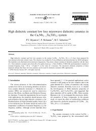
a) <strong>Short</strong> fibre composite b) Laminate composite<br />
c) Hybrid laminates composite<br />
,.......----.. Carbon<br />
Glass<br />
Figure-l.l Schematic model of different composites<br />
1.2 <strong>Fibre</strong> <strong>Reinforced</strong> <strong>Composites</strong><br />
Carbon<br />
The component materials of fibre reinforced composites are fibres and matrix. <strong>Fibre</strong>s<br />
are the load carrying members while the surrounding matrix keeps them in the desired<br />
location and orientation. Further the matrix acts as a load transfer medium and<br />
protects the fibres from environmental damages due to elevated temperature and<br />
humidity. The nature of the interface between them is important as far as the<br />
properties of the composites are concerned. <strong>Fibre</strong> reinforced composites exhibit<br />
7
Chapter 1<br />
<strong>Natural</strong> fibres are classified into three major types as animal fibres, vegetable fibres<br />
and mineral fibres. All animal fibres such as silk, wool and mohair are complex<br />
proteins. They are resistant to most organic acids and to certain powerful mineral<br />
acids. They constitute the fur or hair that serves as the protective epidermal covering<br />
of animals. Silk is an exception to this, which is extruded by the larvae of moths and<br />
insects and is used to spin their cocoons. It is the only filament that commonly reaches<br />
a length of more than 1000 m. Several silk filaments can be gathered to produce<br />
textile yarn and staple form is used to manufacture spin yarns. <strong>Natural</strong>ly crimped wool<br />
fibres produce air trapping yarns that are used for insulating materials. An important<br />
class of naturally occurring mineral fibre is asbestos. Glass fibre is the inorganic<br />
mineral fibre made from silica sand, which is used for commercial applications.<br />
Vegetable fibres can be divided into smaller groups based on their origin within the<br />
plant as given below.<br />
Vegetable <strong>Fibre</strong>s<br />
Seed Bast Fruit Leaf<br />
Normally bast fibers are found in the inner bark of certain plant stems; for example,<br />
,<br />
hemp, jute, flax, ramine, kenaf, etc. They are made up of overlapping cells of bundle<br />
in which fibres are bonded together by pectin. Older bundles are larger, more lignified<br />
and so stiffer. Banana, sisal, pineapple, abaca etc. are fibres of leaf origin. These<br />
fibres are occurring as a part of the fibro vascular system of leaves. Bast and leaf<br />
fibres are generally used in composite applications. The fibres found in fruits and<br />
seeds like that of cotton, kapok, oil palm, coir etc. are not assembled as bundles.<br />
These fibres originate as hairs born on the seeds or inner walls ofthe fruit, where each<br />
9
Chapter 1<br />
derived from organic polymers are termed as organic synthetic fibres, e. g. Nylon,<br />
Terylene, Polyester etc. Most of them are thermoplastics; i.e. they are softened by<br />
heat. The properties of these fibres depend on the base polymer, the spinning process<br />
and the post spinning treatment of the fibre. Carbon and graphite fibres are high<br />
strength materials that are used as reinforcing agents in composites. Carbon fibres are<br />
produced from rayon or acrylic fibres by thermal heating. Carbon fibres are converted<br />
to graphite fibres at temperatures above 25000C. They can also be made from pitch, a<br />
residual petroleum product. The properties of some ofthe synthetic and mineral fibres<br />
are given in Table 1.2.<br />
Table 1.1 Physical and Mechanical properties of some vegetable fibres<br />
Properties Coir Jute Oil palm Sisal Banana<br />
Diametertjnn) 100-400 12-25 50-500 100-300 80-250<br />
Densitytg/cnr') 1.15 1.45 1.5 1.45 1.35<br />
Cellulose (%) 43 61 65 78 65<br />
Lignin (%) 45 12 19 12 5<br />
Moisture (0/0) 10-12 12 16 11 16<br />
Modulus(GPa) 4-6 10-30 2-4 9-20 8-20<br />
Tenacity(MN/m 2 ) 130-175 450-650 240-500 400-700 500-700<br />
Micro fibrillar 4-5 42 10-22 11<br />
angle<br />
Elongation (%) 15-40 1-2 10-14 3-7 1-4<br />
Cost(RsIKg) 9 20 20 15 30<br />
Ref: lG.Cook, Hand book of textile fibre and <strong>Natural</strong> fibres, 4 h Edn; Morrow publishing,<br />
England (1968)<br />
11
Chapter 1<br />
The mechanical properties of natural fibres also depend on the cellulose type, because<br />
each type of cellulose has its own cell geometry and the geometrical constitution<br />
determines the mechanical properties.The three dimensional representation of<br />
cellulose molecule is given in figure 1.4(a) and SEM photograph of cellulose<br />
microfibril is given in figure 1.4 (b)<br />
The crystal structure of natural and regenerated cellulose is known as cellulose-land<br />
cellulose- IT respectively. In cellulose-I the chains within the unit cell are in parallel<br />
configuration [22] while they have antiparallel configuration [23] in cellulose-IT. In<br />
addition to cellulose component, natural fibres contain hemicellulose, which consists<br />
of a group ofpolysaccharides that remain associated with the cellulose after lignin has<br />
been removed. The hemicellulose differs from cellulose in that they contain several<br />
sugar units whereas cellulose contains only glucopyranose units. Hemicellulose also<br />
exhibits considerable chain branching whereas cellulose is strictly linear. The degree<br />
of polymerization of native cellulose is also hundred times higher than that of<br />
hemicellulose. Unlike cellulose, the constituents ofhemicelluloses differ from plant 10<br />
plant [24]. Lignins, complex hydrocarbon with aliphatic and aromatic components are<br />
another important constituent of plant fibres. Lignin is an aromatic biopolymer, an<br />
integral cell constituent in all vascular plants including the herbaceous varieties. The<br />
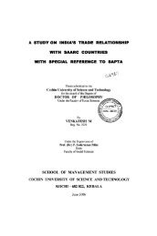
schematic representation ofthe structure offibre is given in figure 1.5.<br />
The major inter unit linkage is an aryl-aryl ether type. Besides twenty types of bonds<br />
present in the lignin itself, lignin seems to be particularly associated with<br />
hemicellulose polysaccharides [25]. Lignin forms the matrix sheet around the fibres<br />
that hold the natural structure together. The mechanical properties of lignin however<br />
are lower than that of cellulose [26]. In addition to these, pectin and waxes make up<br />
parts ofthe fibre [27].<br />
15
Introduction<br />
Bonds between Pectin<br />
and Hemicellulose<br />
......--Pectin<br />
Cellulose fibril<br />
Figure 1.5 Schematic representation of the structure of fibre<br />
1.2.3 Advantages of <strong>Natural</strong> fibres as reinforcement in composites<br />
<strong>Natural</strong> fibres, as a substitute for glass components, have gained interest in 1he last<br />
decade, especially in the housing sector. The moderate mechanical properties of<br />
natural fibres prevent them from being used in high performance applications where<br />
carbon fibre reinforced composites would be utilized, but for many reasons they can<br />
compete with glass fibre. The low specific weight, which results in a higher specific<br />
strength and stiffness than those of glass, is a benefit. The use of renewable natural<br />
fibres contributes to sustainable development. Nowadays natural fibre reinforced<br />
polymer composites come prior to synthetic fibre reinforced composites in properties<br />
such as biodegradability, combustibility, light weight, non toxicity, decreased<br />
environmental pollution, low cost, ease of recyclability etc. These advantages place<br />
16
Chapter 1<br />
the natural fibre composites among the high performance composites having<br />
economical and environmental advantages. The versatile high performance<br />
applications of natural fibre composites, which can replace glass and carbon fibres,<br />
were listed in an article by Hill [28]. The vegetable fibre have density of about half<br />
that of glass fibre. During the processing of natural fibre composites, there will be no<br />
abrasion of the processing machines. These fibres can withstand processing<br />
temperatures up to 250°C. Reinforcement of polymers with vegetable fibres glues<br />
good opportunities for the effective utilization of agricultural products. Physical,<br />
chemical and mechanical properties of some important natural fibres are given in<br />
Table 1.1 [16, 29, and 30]. They are cent percent combustible without the production<br />
of either toxic gases or solid residues. Wright and Mathias succeeded in preparing<br />
lightweight materials from balsawood and polymer [31]. Investigations have been<br />
carried out by Hedenberg and Gatenholm in recycling the plastic and cellulose waste<br />
into composite [32]. Systematic investigations on wood flour reinforced polystyrene<br />
composites have been carried out by Maldas and Kokta [33]. The effects of<br />
hybridization of saw dust with glass and mica and of the surface treatment of the<br />
reinforcing filler on the mechanical properties were studied [34]. <strong>Natural</strong> fibres like<br />
sisal, coir, oil palm, bamboo etc. have been proved to be a better reinforcement in<br />
rubber matrix [35-38]. Incorporation of natural fibres resulted in better long term<br />
mechanical performance of elastomers. The poor reinforcing effect of these cellulosic<br />
fibres in elastomers were overcome by giving specific modifications. The range of<br />
products in the automobile industry based on natural fibres is based on polymers like<br />
plastics and elastomers and fibres like flax, hemp, sisal etc. The use of natural fibres<br />
in automobile industry has grown rapidly over the last five years. Recently value<br />
added composite materials were developed from neisan jute fabric and polypropylene<br />
having enhanced mechanical properties and reduced hydrophilicity [39]. Yamini et al<br />
[40] investigated the effect of board density on the properties of particle board from<br />
17
oil palm fibre and urea formaldehyde resin.<br />
Introduction<br />
<strong>Natural</strong> fibres enjoy the right potential for utilization in composites due to their<br />
adequate tensile strength and good specific modulus, thus ensuring a value added<br />
application avenue. Plant based composites have been widely used in construction; the<br />
ancient Egyptians used to reinforce clay walls. To eliminate problems resulting from<br />
the incorporation of synthetic fibres such as high abrasiveness, health hazards,<br />
disposal problems etc. incorporation of natural fibres is proposed. They are abundant,<br />
renewable, and cheap and are having low density. Material scientists all over the<br />
world focus their attention on natural composites reinforced with fibres like jute, sisal,<br />
coir, pineapple, banana etc. primarily to cut down the cost ofraw materials.<br />
1.2.4 Major drawbacks of <strong>Natural</strong> fibres<br />
a. Moisture absorption offibres<br />
The lignocellulosic natural fibres are hydrophilic and absorb moisture. The swelling<br />
behaviour of natural fibres is generally affected by its morphology as well as physical<br />
and chemical structures. Biofibres change their dimensions with varying moisture<br />
content because the cell wall polymers contain hydroxyl and other oxygen containing<br />
groups, which attract moisture through hydrogen bonding [41]. The hemicelluloses<br />
are mainly responsible for moisture absorption. Water penetration through natural<br />
fibres can be explained by capillary action [42]. The waxy materials present on the<br />
surface help to retain the water molecules on the fibre. The porous nature of the<br />
natural fibre accounts for the large initial uptake at the capillary region. The hydroxyl<br />
group (-OH) in the cellulose, hemicellulose and lignin build a large amount of<br />
hydrogen bonds between the macromolecules in the plant fibre cell wall. Subjecting<br />
the plant fibres to humidity causes the bonds to break. The hydroxyl group then forms<br />
new hydrogen bond with water molecules, which induce swelling [43]. The schematic<br />
representation ofswelling process in cellulose is given in figure 1.6<br />
18
. Thermal stability of natural fibres<br />
Introduction<br />
<strong>Natural</strong> fibres are complex mixtures of organic materials and as a result, thermal<br />
treatment leads to a variety of physical and chemical changes. The limited thermal<br />
stability of natural fibre is one of their drawbacks. The thermal stability of natural<br />
fibres can be studied by Thermo Gravimetric Analysis (TGA). As mentioned above,<br />
natural fibre is composed of mainly cellulose, hemicellulose and lignin. Each of the<br />
three major components has its own characteristic properties with respect to thermal<br />
degradation which are based in polymer composites. However the microstructure and<br />
the three dimensional nature of natural fibre are variables, that also play important<br />
roles in terms of their effects on combustion behaviour. Thus the individual chemical<br />
components ofthe fibre behave differently ifthey are isolated or ifthey are intimately<br />
combined within each single cell ofthe fibre structure [44].<br />
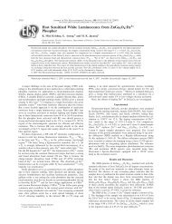
Lignin, specifically the low molecular weight protolignin, degrades first and at a<br />
slower rate than the other constituents. This is shown in figure 1.7(a). The TGA curve<br />
indicates that the beginning of the natural fibre degradation occurs at around 180°C<br />
but the rate ofdegradation is always lower than that ofthe cellulose, Figure 1.7(b).<br />
This process has been described by Shurky and Girgis [45] who also presented an<br />
analysis of the products of degradation. From figure I.7(b) it is observed that the<br />
weight loss in the cellulose sample is negligible below 300°C. However above that<br />
temperature the cellulose begins to degrade fast and at about 400°C only the residual<br />
char is found. Beall [46] has described this process as the loss ofhydroxyl groups and<br />
depolymerization ofthe cellulose to anhydroglucose units. The thermal degradation of<br />
cellulose based fibres is greatly influenced by their structure and chemical<br />
composition. The natural fibre starts degrading at about 240°C. The thermal<br />
degradation of lignocellulosic materials has been reviewed by Tinh et al in detail for<br />
modified and unmodified materials [47-48]. Thermal degradation ofnatural fibres is a<br />
20
Chapter 1<br />
two stage process, one in the temperature range 80-180°C and other in the range 280<br />
380°C.<br />
(b)<br />
(a)<br />
Figure 1.7 TG I DTG Vs Temperature curves of (a) Lignin<br />
(b) Cellulose<br />
[Ref: Marcovich N.E., Reboredo MM, Aranguren ML, Thermochemica Acta,<br />
(2001)372:45<br />
21
Introduction<br />
Gossan and Bledzki [49] studied the thennal degradation pattern ofjute and flax and<br />
found that at temperatures below 170°C fibre properties were affected only slightly<br />
while at temperatures above 170°C significant drop in tenacity and degree of<br />
polymerization were observed. Because of chain sessions, a slight increase in the<br />
degree of crystallinity was observed. Thermal degradation pattern of other cellulosic<br />
fibres like oil palm, sisal, banana, coir, hemp, jute etc. was also reported [50-55]. It<br />
was reported that the chemical modification improved the thermal stability of their<br />
composites. Chemically modified fibres showed a satisfactory thermal stability at<br />
processing temperatures for potential composites. Thermal degradation of natural<br />
fibres is a two stage process. The low temperature degradation [80-180°C] process is<br />
associated with degradation of lignin, whereas the high temperature degradation [280<br />
380°C] process is due to cellulose. The degradation ofnatural fibres is a crucial aspect<br />
in the development of natural fibre composites and thus has a bearing on the curing<br />
temperature in the case of elastomers and thermosets and extrusion temperature in<br />
thermoplastic composites [56-57].<br />
c. Biodegradation and Photo degradation of <strong>Natural</strong> fibre<br />
The lignocellulosic natural fibres are degraded biologically by very specific enzymes<br />
capable of hydrolyzing the cellulose especially hemicellulose present in the cell wall<br />
into digestible units [58]. Lignocellulosic exposed outdoors undergo photochemical<br />
degradation caused by ultraviolet light. Resistance to biodegradation and ultraviolet<br />
radiation can be improved by bonding chemicals to cell wall or by adding polymer to<br />
the cell matrix. Biodegradation of cellulose causes weakening the strength of the<br />
natural fibre. Photo degradation primarily takes place in the lignin component which<br />
is responsible for the colour changes [59]. The surface becomes richer in cellulose<br />
content as the lignin degrades. In comparison to lignin, cellulose is much less<br />
susceptible to ultraviolet degradation.<br />
22
Chapter 1<br />
1.2.5 Matrix materials<br />
Since fibres cannot transmit loads from one to the other, they have limited use in<br />
engineering applications. When they are embedded in a matrix material to form a<br />
composite, the matrix serves to bind the fibres together, transfers loads to the fibres,<br />
and protect them against environmental attack and damage due to handling. The<br />
matrix has a strong influence on several mechanical properties of the composite such<br />
as modulus and strength, shear properties and properties in compression. Physical and<br />
chemical characteristics of the matrix such as melting or curing temperature, viscosity<br />
and reactivity with fibres influence the choice of fabrication process. The matrix<br />
material for a composite system is selected, keeping in view all of the above factors.<br />
The commonly used matrix materials are polymers, metals and ceramics.<br />
Polymers<br />
Polymers are the most widely used matrix materials for fibre reinforced composites.<br />
Their chief advantages are low cost, easy processability, good chemical resistance and<br />
low specific gravity. On the other hand low strength, low modulus and low operating<br />
temperature limit their use. Polymers are further classified into plastics and rubbers.<br />
a. Plastics<br />
Organic polymeric materials which can be made into desired shape through extrusion,<br />
moulding, casting etc. are termed as plastics. According to their structure and thermal<br />
behaviour, plastics are classified into thermoplastics and thermosetting plastics.<br />
Plastics that soften or melt on heating are called thermoplastics. Melting and<br />
solidification ofthese polymers are reversible and they can be reshaped by application<br />
of heat and pressure. They are semi crystalline or amorphous in nature. Examples<br />
include polyethylene, polypropylene, polyamides, polystyrene, polyacetate,<br />
polycarbonate, polyether ether ketone etc. Thermosetting plastics have cross-linked or<br />
network structures which do not soften but decompose on heating. Once solidified by<br />
cross linking process, they cannot be reshaped. Common examples of thermosets are<br />
23
Introduction<br />
polyester resins, epoxies, phenolics, melamines, silicons etc. Thermoplastics are<br />
almost exclusively used when no reinforcement is included in non structural<br />
applications and dominates also when short fibres are incorporated. However<br />
thennosets clearly dominate in structural composite applications. Thermoplastics have<br />
lately received increased attention in continuous fibre reinforced composite due to a<br />
number ofattractive potential applications.<br />
b. <strong>Rubber</strong>s<br />
<strong>Rubber</strong> is a versatile and adaptable material that has been successfully used as matrix<br />
for composite preparation. <strong>Rubber</strong> is defined as a material that is capable of<br />
recovering from larger elastic deformations quickly and forcibly. They can be<br />
modified to a state in which it is essentially insoluble but can swell in solvents like<br />
benzene, toluene, methyl ethyl ketone etc. [60]. <strong>Rubber</strong> is unique but to following<br />
properties. Its elastic strain is much higher than that of metal. Hence it can function at<br />
high strains. It is stretched rapidly even under small load to about 1000% elongation.<br />
On releasing the applied forces, rubber retracts rapidly almost fully. There are<br />
different types of rubber including <strong>Natural</strong> rubber (NR) and a variety of synthetic<br />
rubbers.<br />
(i) <strong>Natural</strong> rubber<br />
<strong>Natural</strong> rubber is a high molecular weight polymer of isoprene in which essentially all<br />
the isoprene's have the cis 1-4 configuration.<br />
Figure 1.8 Structural formula of natural rubber<br />
24
Chapter 1<br />
The chemical structural formula ofnatural rubber is shown in figure 1.8.<br />
In its very natural state, rubber exists as a colloidal suspension in water in the latex of<br />
rubber producing plants - Hevea Brasiliensis.<br />
Approximate composition ofthe field latex is given in Table 1.3.<br />
Table 1.3 Composition of field latex<br />
Constituents Quantity<br />
<strong>Rubber</strong> hydrocarbon 33°A.<br />
Water 60°A.<br />
Protein 2-3 %<br />
Fatty acids 1-3 %<br />
Sugars 1%<br />
Ash content<br />
1 0A.<br />
Trace elements (Cu, Mn ) 2-3 ppm<br />
Impurities 8-10 ppm<br />
Among various rubbers, natural rubber is very important since it possess the general<br />
features of other rubbers in addition to the following highly peculiar characteristics.<br />
Since it is of biological origin, it is renewable, inexpensive and creates no health<br />
hazard problems. It possesses high tensile strength due to strain induced<br />
crystallization. It possesses superior building tack, which is essential in many products<br />
like tyres, hoses, belts etc. It possesses good crack propagation resistance also. The<br />
field latex is concentrated by centrifugation, creaming or electrodecantaion. Generally<br />
the latex is coagulated by formic or acetic acid. Technical grading of rubber is done<br />
according to composition of rubber, source material, initial plasticity etc. The main<br />
criterion is the dirt content which is the residue left after the rubber sample was<br />
dissolvedin an appropriate solvent, washed through a 45Jlrn sieve and dried.<br />
25
Chapter 1<br />
(b) Polybutadiene rubber (BR) which is a homopolymer ofbutadiene monomer. BR is<br />
cis-I, 4 Polybutadiene. BR has very good low temperature properties due to its low Tg<br />
value. As the trans content in the polymer increases, tendency for crystallization<br />
increases. BR has high air permeability, low heat build up, high resilience, better flex<br />
resistance, heat stability etc. it is used in manufacture of mechanical goods and as<br />
modifier for plastics to improve impact resistance.<br />
(c) Ethylene propylene rubbers are available in two types. EPM-Ethylene propylene<br />
eo polymer and EPDM- Ethylene propylene diene monomers. The alternating<br />
distribution of monomers in the EPM and EPDM rubbers provide most amorphous or<br />
least crystalline rubber. In EPDM, small amount of diene is incorporate along with<br />
ethylene and propylene at the time of polymerization. The dienes are added to<br />
ethylene propylene rubber to make it sulphur curable. These rubbers have a<br />
remarkable resistance to ozone and DV radiation. The combination of weather<br />
resistance, excellent electrical properties and the ability to be cured rapidly with<br />
peroxide has been made use of this rubber in production of good quality electrical<br />
cables.<br />
(d) Poly isoprene rubber (IR): In general this rubber can be used in areas where NR is<br />
used due to the inherent tack, high gum strength, good hysterisis, good hot tear and<br />
tensile properties.<br />
(e) Butyl rubber (IIR): It is a copolymer of isobutylene and butadiene or isoprene.<br />
Butyl rubber is not as resilient as natural rubber. It is extremely resistant to oxidation<br />
and to the action of corrosive chemicals. Because of its it low permeability to gas,<br />
butyl rubber is used widely for inner tubes in automobile tyres.<br />
Special purpose synthetic rubbers include chloroprene rubbers, nitrile rubbers,<br />
polyacrylic rubbers, fluorocarbon rubbers, silicon rubbers, polyurethane rubbers and<br />
polysulphide rubbers. These types of rubbers are used in specific applications which<br />
require solvent resistance, fire resistance and thermal resistance [61].<br />
27
Chapter 1<br />
matrix. Composite materials with weak interface have relatively low strength and<br />
stiffness but high resistance to fracture whereas materials with strong interface have<br />
high strength and stiffness but are very brittle. The effects are related to the ease of<br />
debonding and pull out of fibres from the matrix during crack propagation. The<br />
interface/interphase concept in fibre composite is clear from the figure 1.9 [74].<br />
Interface is defined as a two dimensional region between fibre and matrix having zero<br />
thickness. The interphase in a composite is the matrix surrounding a fibre. There is a<br />
gradient in properties observed between matrix and interphase. The interface is an<br />
area whereas interphase is a volume.<br />
The fibre matrix interface adhesion can be explained by five main mechanisms.<br />
(i) Adsorption and Wetting<br />
This is due to the physical attraction between the surfaces, which is better understood<br />
by considering the wetting of solid surfaces by liquids. Between two solids, the<br />
surface roughness prevents the writing except at isolated points. When the fiber<br />
surface is contaminated, the effective surface energy decreases. This hinders a strong<br />
physical bond between fibre and matrix interface.<br />
(ii) Interdiffusion<br />
Polymer molecules can be diffused into the molecular network ofthe other surface say<br />
fibre as shown in figure 1.10 a. The bond strength will depend on the amount of<br />
molecular conformation, constituents involved and the ease ofmolecular motion.<br />
(iii) Electrostatic attraction<br />
This type oflinkage is possible when there is a charge difference at the interface. The<br />
electrostatic interaction at the interface is shown in figure 1.10 (b) & (c). The anionic<br />
and cationic species present at the fibre and matrix phases will have an important role<br />
in the bonding of the fibre matrix composites via electrostatic attraction. Introduction<br />
of coupling agents at the interface can enhance bonding through the attraction of<br />
cationic functional groups by anionic surface and vice versa.<br />
29
(a)<br />
///////////////////<br />
+ + + + + + + + + +<br />
(c)<br />
(e)<br />
Introduction<br />
1111111111///////1/<br />
+ + + + + + + + + +<br />
7777777777777777777<br />
Figure 1.10 Schematic representations of various fibre matrix adhesions.<br />
(iv) Chemical bonding<br />
Chemical bonds can be formed between chemical groups on the fibre surface and a<br />
compatible chemical group in the matrix as shown in figure 1.10 (d). The type ofbond<br />
determines the strength. Interfacial chemical bonding can increase the adhesive bond<br />
strength by preventing molecular slippage at a sharp interface during fracture and by<br />
increasing the fracture energy by increasing the interfacial attraction.<br />
30<br />
(d)
Chapter 1<br />
(v) Mechanical adhesion<br />
Mechanical interlocking at the fibre-matrix interface is possible as given in fig 1.10<br />
(e). The degree of roughness of the fibre surface is very significant in determining the<br />
mechanical and chemical bonding at the interface. This is due to the larger surface<br />
area available on a rough fibre. Surface roughness can increase the adhesive bond<br />
strength by promoting wetting or providing mechanical anchoring sites.<br />
<strong>Natural</strong> fibres are hydrophilic in nature and are incompatible with the hydrophobic<br />
polymer matrix and have a tendency to form aggregates. Since they are hydrophilic<br />
fibres they are very sensitive to moisture absorption. To eliminate the problems<br />
related to high water absorption, treatment of fibres with hydrophobic reagents has<br />
been attempted. These reagents contain reactive functional groups that are capable of<br />
bonding to the reactive groups in the matrix polymer. Tle modification of natural<br />
fibres is done to make fibres hydrophobic and to improve the interfacial adhesion<br />
between the fibre and the polymer matrix [75-85]. In addition to the surface<br />
treatments of fibres, use of a compatibilizer or coupling agent for effective stress<br />
transfer across the interface can also be explored [86-91]. The compatibilizer can be a<br />
polymer with functional groups grafted in to the chain of the polymer. The coupling<br />
agents are generally tetra functional organometallic compounds based on silicon,<br />
called silanes [92]. Pedro et al found that pre impregnation of cellulose fibres in a<br />
LDPE/xylene solution and the use of a coupling agent result in small increment in<br />
mechanical properties of LDPE, reinforced with green cellulosic fibre composites<br />
which are attributed to an improvement in the interface between fibres and matrix.<br />
The fibre treatment also improved the shear properties of the composite and fibre<br />
dispersion in the matrix [93]. Ishak et al [94] used silane coupling agents and<br />
compatibilizers to improve the mechanical properties of oil palm fibre filled high<br />
density polyethylene composites. In all cases it seems that the mechanical properties<br />
of the composites have improved significantly. The use of silane coupling agent<br />
31
Introduction<br />
enhanced the tensile properties and tear strength of bamboo fibres filled rubber<br />
composites [95]. The silane coupling agent is believed to improve the surface<br />
functionality of bamboo fibres and subsequently enabled the bamboo fibres to bond<br />
chemically to the rubber matrix. The wetting of cellulosic fibres in rubber matrix is<br />
also improved by the use of coupling agent. According to Damka, [96] the use of<br />
silanes permits within a shorter vulcanization time, an increase in rubber bound<br />
sulphur and gives vulcanizates of increased strength.<br />
Usually natural fibres are treated with NaOH to remove lignin, pectin and waxy<br />
substances. Alkalization gives rough surface topography to the fibre. It also changes<br />
the fine structure of native cellulose I to cellulose IT [97]. The increase in the<br />
percentage crystallinty index of alkali treated fibre occurs because of the removal of<br />
cementing materials which leads to better packing of cellulose chain and increase in<br />
molecular orientation. The elastic modulus of the fibre is expected to increase with<br />
increasing degree of molecular orientation [98]. Superior mechanical properties of<br />
alkali treated jute based biodegradable polyester composites was attributed to the fact<br />
that alkali treatment improves the fibre surface characteristics by removing the<br />
impurities if the fibre surface thereby producing a rough surface morphology [99].<br />
The effect of alkalization and fibre alignment on the mechanical and thermal<br />
properties of kenaf and hemp fibre reinforced polyester composites were studied by<br />
Aziz and Ansell [100]. Samal et al [101] studied the effect of alkali treatment and<br />
cyanoethylation on coir fibres and found that the modified coir fibre showed<br />
significant hydrophobicity, improved tensile strength and moderate resistance to<br />
chemical reagents. Hill et al [102] studied the benefit of fibre treatment by chemical<br />
modification (acetylation) ofthe fibres and by the use of silane coupling agent on the<br />
mechanical properties of oil palm and coir fibre reinforced polyester composites. They<br />
found that acetylation of coir and oil palm fibres results in the increase in the<br />
interfacial shear strength between the fibre and the matrix and increase in the<br />
mechanical properties of the composites. George et al [103] analyzed the improved<br />
32
Chapter 1<br />
interfacial interaction in chemically modified pine apple leaf fibre reinforced<br />
polyethylene composites. They used various reagents like NaOH, silanes and<br />
peroxides to improve the interfacial bonding. The influence of fibre surface<br />
modification on the mechanical performance of oil palm fibre reinforced phenol<br />
formaldehyde composites were studied by Sreekala et al [104]. The effects of various<br />
chemical modifications of jute fibres as a means of improving its suitability as<br />
reinforcement in biopol based composites were done by Mohanty et al [105]. Sisal<br />
fibres were chemically treated with a two step treatment with sodium sulphate<br />
solution followed by acetic anhydride to promote adhesion to a polyester resin matrix<br />
[106]. It was found that the chemical treatment improved the fibre matrix interaction<br />
as revealed by the brittle behaviour of the composites reinforced with treated fibres.<br />
Though the treatment improved the fibre behaviour in relation to moisture, the water<br />
absorption capacity of the composites was increased by the treatment. This should be<br />
due to the failure to remove all the unreacted hydrophilic species left by treatment or<br />
to the formation of acetyl cellulose micro tubes in the treated fibre. Rozman et al<br />
[107] employed lignin as compatibilizers in coconut fibre polypropylene composites.<br />
Since lignin contains both polar hydroxyl groups and nonpolar hydrocarbon and<br />
benzene ring it can play a role in enhancing the compatibility between both<br />
components. The composite with lignin as a compatibilizer possessed higher flexural<br />
properties compared to the control composites. Lignin also reduces water absorption<br />
and thickness swelling of the composites. Thomas and coworkers [108-113] have<br />
carried out systematic studies on the chemical modification of various natural fibres<br />
like sisal, coir, oil palm, banana and pineapples and its reinforcing effect on various<br />
rubbers, thermoplastics and thennosets. In all cases it was observed that the composite<br />
properties have greatly improved by using treated fibres due to better fibre matrix<br />
interaction.<br />
The studies so far reported proved that the utilization of natural fibres in polymeric<br />
33
Chapter 1<br />
1.4 <strong>Short</strong> fibre reinforced rubber composites<br />
<strong>Short</strong> fibre reinforced rubber composites were developed to fill the gap between the<br />
long fibre reinforced and particulate filled rubber composites. That is mainly to<br />
achieve the high performance of the fibre coupled with easy processability and<br />
elasticity ofthe rubber. <strong>Composites</strong> in which the short fibres are oriented uniaxially in<br />
an elastomer have a good combination of good strength and stiffness from the fibres<br />
and elasticity from the rubber. These composites are being used for the fabrication of<br />
a wide variety of products such as v-belts, hoses and articles with complex shapes<br />
(114-115). <strong>Short</strong> fibre reinforced rubber composites possess several advantages over<br />
continuous fibre composites (116-119). <strong>Short</strong> fibres can be easily incorporated into<br />
the rubber compound along with other ingredients. They are amenable to standard<br />
rubber processing operations such as extrusion, calendaring, compression moulding,<br />
injection moulding etc. These composites provide high green strength and high<br />
dimensional stability during fabrication. Design flexibility is another advantage of<br />
these composites. Complex shaped articles which is quite difficult to accomplish with<br />
long fibre composites can be fabricated using short fibre composites. Mechanical<br />
properties like specific strength and stiffness, reduced shrinkage in moulded products,<br />
resistance to solvent swelling, abrasion, tear and creep resistance are greatly improved<br />
in the case of short fibre composites. Moreover short fibres are cheaper than long<br />
fibres. There are some disadvantages also for short fibre composites. Difficulty in<br />
achieving uniform dispersion, fibre breakage during processing, difficulties in<br />
handling and bonding etc. are some among them.<br />
1.5 Factors affecting the properties of short fibre rubber composites<br />
By controlling the factors such as aspect ratio (length to diameter ratio) of the fibre,<br />
orientation of fibres, by establishing a high degree of fibre dispersion and fibre matrix<br />
adhesion, reasonably good rubber products can be fabricated using short fibres. The<br />
rubber compounds containing short fibres have been found to possess good<br />
35
Introduction<br />
dimensional stability and higher green strength. The reinforcement caused by short<br />
fibres with the polymer matrix is governed by the following factors.<br />
These include mixing of rubber compounds, fibre dispersion, fibre orientation, fibre<br />
breakage, critical aspect ratio of the fibre, fibre matrix adhesion, fibre concentration<br />
etc.<br />
1.5.1 Mixing of rubber compounds<br />
The conventional mixers like Banbury and open two roll mixing mill can be utilized<br />
for mixing of short fibres with rubbers as described Boustany and Coran (120). The<br />
mixing procedure may be distributive or dispersive depending on the type of the fibre<br />
used. The distributive mixing increases randomness of spatial distribution of the<br />
minor constituent within the major base material without further size reduction, while<br />
dispersive mixing serves to reduce the agglomerate size. Thus brittle fibres like glass<br />
or carbon which break severely during mixing require more distributive mixing but<br />
for organic fibres such as nylon, and natural cellulosic fibres dispersive mixing is<br />
preferred since these fibres tend to agglomerate during mixing procedure.<br />
1.5.2. <strong>Fibre</strong> dispersion<br />
Good dispersion of short fibres in the rubber compounds is an essential requisite for<br />
high performance composites. The naturally occurring cellulosic fibres tend to<br />
agglomerate during mixing due to hydrogen bonding. A pretreatment offibres at times<br />
is necessary to reduce fibre-fibre interactions. <strong>Natural</strong> fibres treated either with carbon<br />
black or compositions containing latex were found to be dispersing well in the rubber<br />
matrix [121]. <strong>Fibre</strong> length has also a small effect to facilitate better dispersion.<br />
Derringer [122] has used commercially available fibres such as nylon, rayon,<br />
polyester and acrylic flock cut into smaller lengths of8-10 cm for better dispersion.<br />
1.5.3. <strong>Fibre</strong> breakage<br />
The importance of fibre length and its influence on the properties of the composites<br />
were studied by several researchers [123-126]. In a composite material fibre length is<br />
a critical factor which should not be too long so that they entangle with each other<br />
36
Chapter 1<br />
causing problems of dispersion. But a very small length of fibre does not offer<br />
sufficient stress transfer from the matrix to the fibre. The severity of fibre breakage<br />
mainly depends on the type of fibre and its initial aspect ratio. <strong>Fibre</strong>s like glass and<br />
carbon are brittle and they posses a low bending strength than cellulosic fibre which<br />
are more flexible and resistant to bending. For each type of fibre there exists a certain<br />
aspect ratio below which no further breakage can occur depending on its resistance to<br />
bending. The aspect ratio of glass fibre is very low compared to cellulosic fibres. If<br />
the mix viscosity is high, more shear will be generated during mixing and thus<br />
exceeding the critical bending stress of the fibre which eventually results in severe<br />
breakage. O'Connar [127] has reported the fibre breakage during mixing. The lower<br />
reinforcing ability of the glass fibre has been attributed to severe reduction in their<br />
length compared to cellulosic fibres during mixing. Murthy and De [128] suggested<br />
that the breakage of the fibre is due to the buckling effect. De et al [129-131] have<br />
studied the breakage ofjute and silk fibres in natural rubber, and NBR and found that<br />
the breakage ofsilk fibres is less than that ofjute fibres.<br />
1.5.4. Critical fibre length and aspect ratio of fibre<br />
In a perfectly oriented unidirectional continuous fibre reinforced polymer composite<br />
containing fibres of uniform radius, the rate of increase of fibre stress is proportional<br />
to the interfacial shear stress and the fibre ends have very little influence on the<br />
properties of the composites. But the fibre ends in short fibre composites play a major<br />
role in the determination of ultimate properties. The concept of critical fibre length<br />
over which the stress transfer allows the fibre to be stressed to its maximum, or at<br />
which efficient fibre reinforcement can be achieved has been used to predict the<br />
strength of the composites. Broutmann and Agarwal [132] have done a theoretical<br />
analysis on the mechanism of stress transfer between matrix and fibre of uniform<br />
length and radius and have given the following expression for the critical fibre length<br />
Clc)·<br />
37
Introduction<br />
lc/d = stt2ty........................... 1.1<br />
where d is the diameter of the fibre, st is the ultimate fibre strength, and t y is the<br />
matrix yield stress in shear. The aspect ratio (the length to diameter ratio) (lid) of<br />
fibres is a major parameter that controls the fibre dispersion, fibre matrix adhesion<br />
that gives the optimum performance of short fibre polymer composites. If the aspect<br />
ratio of the fibre is lower than the critical aspect ratio, insufficient stress will be<br />
transferred and the reinforcement will be inefficient. Several researchers [129,133<br />
135] have suggested that an aspect ratio in the range of 100-200 is essential for high<br />
performance fibre rubber composites for good mechanical properties. However<br />
Chakraborthy [130] has observed that an aspect ratio of 40 gives optimum<br />
reinforcement in the case ofcarboxylated nitrile rubber composite reinforced with jute<br />
fibre. Murthy and De [136-137] have reported that an aspect ratio of 15 and 32 are<br />
sufficient for reinforcement of jute fibre in natural rubber and styrene butadiene<br />
rubber respectively. It was reported that for synthetic fibre like polyester and nylon an<br />
aspect ratio of 220 and 170 gives good reinforcement in natural rubber vulcanizates<br />
[138-139].<br />
1.5.5. <strong>Fibre</strong> orientation<br />
<strong>Fibre</strong> orientation has a significant influence on the physico mechanical properties of<br />
fibre reinforced rubber composites. The preferential orientation of fibres in the matrix<br />
results in the development of anisotropy in the matrix. With respect to orientation<br />
three limits are explained as longitudinal (along machine direction), transverse (across<br />
machine direction) and random as given in figure 1.11 below. It was observed that<br />
during mixing procedure, lower the nip gap higher the anisotropy in tensile properties<br />
of the composites implying greater orientation of fibres. This has represented as<br />
anisotropy index, which reduces gradually with increasing nip gap. During processing<br />
and subsequent fabrication of short fibre polymer composites, the fibres oriented<br />
preferentially in a direction depending upon the nature of flow i.e., convergent and<br />
divergent as explained by Goettler [140].<br />
38
Introduction<br />
i.e., strength lies between the limits of longitudinally and transversely oriented<br />
composites. These composites are essentially isotropic in plane. i.e., they have<br />
desirable properties in all directions in a plane. Longitudinally oriented composites are<br />
inherently anisotropic.<br />
Recently Thomas and eo workers [141] have evaluated the % extent of orientation<br />
from green strength measurements, by using the following equation<br />
Orientation % SJSG,L 1.2<br />
SJSG+ Sr/SG<br />
Where S represents green strength of the composite and subscript L, T denotes<br />
longitudinal and transverse orientation and G represents the gum compound<br />
respectively. Many researchers have used SEM of the fracture surface to determine<br />
the fibre orientation due to the ease ofsample preparation [142-143].<br />
1.5.6. <strong>Fibre</strong> concentration<br />
Concentration of fibres in the matrix plays a crucial role in determining the<br />
mechanical properties of the fibre reinforced polymer composites. A lower<br />
concentration of fibres gives lower mechanical strength. This has been observed not<br />
only in rubbers [144] but also in thermoplastic elastomeric matrices [145-148]. This<br />
behaviour has been attributed basically to two factors, 6) dilution of the matrix which<br />
has a significant effect at low fibre loadings and (ii) reinforcement ofthe matrix by the<br />
fibres which becomes of increasing importance as fibre volume fraction increases. At<br />
low fibre content, 1he matrix is not restrained by enough fibres and highly localized<br />
strains occur in the matrix at low strain levels causing the bond between fibres and the<br />
matrix to break, leaving the matrix diluted by non reinforcing debonded fibres. At<br />
high fibre concentrations, the matrix is sufficiently restrained and stress is more<br />
eventually distributed thus the reinforcement effect outweighs the dilution effect<br />
[149]. As the concentration of fibres is increased to a higher level the tensile<br />
properties gradually improve to give strength higher than that of the matrix. The<br />
concentration of fibres beyond which the properties of the composite improve above<br />
40
Chapter 1<br />
the original matrix strength is known as optimum fibre concentration. In order to<br />
achieve improvement in mechanical properties with short fibres, the matrix is loaded<br />
beyond this volume fraction of fibre. In rubbers this optimum fibre concentration is<br />
quite often found to lie between 25 and 35 phr. This has been observed by several<br />
researchers [150-154] for various natural and synthetic fibres in rubbers. Quite often<br />
at concentration beyond 35 to 40 phr the strength again decreases, because there is<br />
insufficient matrix material to adhere the fibres together.<br />
1.5.7. <strong>Fibre</strong> matrix adhesion<br />
<strong>Fibre</strong> to matrix adhesion plays a very prominent role in the reinforcement of short<br />
fibres in the polymer matrices. The fibre matrix is important in determining the<br />
mechanical, dynamic mechanical and rheological characteristics of the composites<br />
since the stress transfer occurs at the interface from matrix to fibre.<br />
Though the mechanism of stress transfer is not clear, it has been postulated that it<br />
takes place through shearing at the fibre matrix interface. In composites with low fibre<br />
matrix adhesion Derringer [155] observed that a region c:f yielding occurs extending<br />
over a large portion of the strain range which is accompanied by low tensile strength<br />
and high permanent set. The fibre matrix adhesion is evaluated at the interface of the<br />
composites. Interface is an essentially bi-dimensional region through which material<br />
parameters such as concentration of an element, crystal structure, elastic modulus,<br />
density and coefficient of thermal expansion change from one side to another. There<br />
are two types of interface bonding in fibre reinforced composites. They are<br />
mechanical interface bonding and chemical bonding at the interface. In the former one<br />
a simple mechanical anchoring between the two surfaces that can lead to a<br />
considerable degree of adhesion. Moreover, any contraction of the polymeric matrix<br />
on to the fibre would result in gripping ofthe fibre by the matrix. Chemical bonding at<br />
the interface can occur in two ways by dissolution and wettability bonding or by<br />
reaction bonding. In wettability bonding the interaction between the fibre and tbe<br />
41
Introduction<br />
matrix occurs on an electronic, scale i.e., these components come into an intimate<br />
contact on an atomic scale. Hence both surfaces should be approximately wetted to<br />
remove any impurities. In reaction bonding, transport of atoms occurs from the fibre,<br />
matrix or both to the interface. These polar surfaces can form bonding owing to the<br />
diffusion of matrix molecules to the molecular net work of the fibre, thus forming<br />
tangled molecular bonds at the interface. E.g., reaction bonding by coupling agents<br />
likes silane.<br />
<strong>Fibre</strong> matrix adhesion has been explained by the evidences like mechanism of dry<br />
bonding system, fibre treatment and determination of the adhesion level and<br />
optimization. The dry bonding system commonly used in rubbers is the HRH system<br />
consisting of hydrated silica, resorcinol and hexa methylene tetramine to create<br />
adhesion between fibre and rubber matrix. If the fibres are not properly bonded with<br />
the matrix it will slide past each other under tension deforming the matrix to low<br />
strength. When the fibre matrix interface is sufficiently strong, the load will be<br />
effectively transferred to fibres to obtain a high performance composite. Hence the<br />
mechanism of load transfer may take place through the shear at the interface.<br />
O'Connar [127] have studied the effect ofthree bonding system like HRH system, and<br />
a resin bonding agent on NR composites containing various synthetic and natural<br />
fibres. To improve the adhesion between fibres and matrix various oxidative and non<br />
oxidative chemical treatments are available for natural and synthetic fibres [156-157].<br />
Anthome et al and Coran et al [158-159] have reviewed the reinforcement of<br />
elastomers with various treated short cellulosic fibres and their mechanism of<br />
reinforcement. Several researchers have investigated the use of treated short natural<br />
fibres as reinforcing elements for rubber composites [153,154,160-163]. These<br />
include jute, coir, sisal, oil palm, bamboo etc.<br />
A good extent of adhesion is required for high performance short fibre composites.<br />
The main problem with adhesion in short fibre rubber composites is that it cannot be<br />
measured quantitatively. The adhesion level can be qualitatively assessed from the<br />
42
Chapter1<br />
shapes of the stress strain curves and the study of fracture surfaces using scanning<br />
electron microscope techniques. Restricted equilibrium swelling technique can also be<br />
used to evaluate adhesion [164]. But this measurement is inaccurate since the<br />
restriction may be due to the presence of fibres and the adhesion cannot be separated<br />
out. In the case of viscoelastic properties, with the increase of adhesion level a high<br />
shear will be experienced at the interface thereby the mechanical loss associated with<br />
it also increases. At elevated temperature the interface deteriorates and the value<br />
decreases. The studies so far reported proved that utilization of natural fibres as<br />
reinforcement in polymer composites offer economical, environmental and qualitative<br />
advantages. By the incorporation of natural fibres along with synthetic fibres<br />
composites with high performance can be prepared. They may fmd application in<br />
automotive industry as well as building industry.<br />
1.6 Hybrid composites<br />
The development of composite materials based on reinforcement of two or more<br />
fibres in a single matrix, which leads to the development of hybrid composites with a<br />
great diversity of material properties. Research revealed that the behaviour of hybrid<br />
composites appears to be the weighed sum of the individual components in which<br />
there is a more favorable balance between the advantages and disadvantages inherent<br />
in any composite material [165]. It is generally accepted that properties of hybrid<br />
composites are controlled by factors such as nature of matrix, nature, length and<br />
relative composition of the reinforcements, fibre matrix interface and hybrid design<br />
[166,167]. Sisal and glass fibres are good examples of hybrid composites possessing<br />
very good combined properties [168]. Due to the superior properties of glass fibres,<br />
the mechanical properties of the hybrid composites increase with increase in the<br />
volume fraction of glass fibres. Thomas et al [167] have studied the properties of<br />
sisal/sawdust hybrid fibre composites with phenol formaldehyde resin as a function of<br />
sisal fibre loading. It has been found that mechanical properties like tensile and<br />
43
Introduction<br />
flexural strength increases with sisal fibre content. This is due to the fact that the sisal<br />
fibre possesses moderately higher strength and modulus than saw dust. Mishra et al<br />
[169] studied the mechanical properties of sisal and pineapple /glass fibre reinforced<br />
polyester composites. They found that the addition of small amount of glass fibres to<br />
the pineapple leaf fibre and sisal fibre reinforced polyester matrix enhanced the<br />
mechanical properties of the resulting hybrid composites. Rozman et al [170] studied<br />
the tensile and flexural properties of polypropylene/oil palm/glass fibre hybrid<br />
composites and found that incorporation of both fibres into the polypropylene matrix<br />
improved the tensile and flexural strength by the increasing level of overall fibre<br />
loading. Junior et al [171] used plain weaved hybrid ramie-cotton fibres as<br />
reinforcement for polyester matrix. The tensile behaviour was dominated by the<br />
volume fraction of the ramie fibres aligned with the test direction. Cotton fibre had a<br />
minor reinforcement effect. This was due to the weak cotton polyester interface as<br />
well as poor cotton alignment. Hybrid composites containing glass fibre mat and coir<br />
fibre mat in polyester matrix was prepared by Rout et al [172]. Hybrid composites<br />
containing surface modified coir fibres showed significant improvement in flexural<br />
strength and reduced water absorption. Sreekala et al [173] prepared high<br />
performance phenol formaldehyde composite reinforced with oil palm and glass<br />
fibres. It has been found that there exists a positive hybrid effect for the flexural<br />
modulus and unnotched impact strength. <strong>Natural</strong> rubber composite reinforced with<br />
sisal/oil palm, sisal/coir hybrid fibres were prepared by Maya et al [174] and Haseena<br />
et al [175] found that the hybridization has a significant effect in improving the<br />
mechanical properties of the natural rubber composite when compared with the<br />
composite containing individual fibres.<br />
1.7 Cellulose micro fibrils reinforced composites<br />
Due to the biological origin, cellulose fibres display a unique structural hierarchy;<br />
they are composed of an assembly ofmicro fibrils which in turn consists of a number<br />
of cellulose molecules. These molecules which constitute the basic common element<br />
44
Chapter 1<br />
of all celluloses consist of long linear chains of poly-B-(1-4)-D-glucosyl residues<br />
organized in perfect stereo regular configuration. During biosynthesis, these chain<br />
themselves get packed into slender micro fibrils of extreme length, whose diameters<br />
range from 2 to 20 nm depending upon the sample origin. Within each micro fibril,<br />
the cellulose molecules are organized in a crystalline order which results from a<br />
regular network of intra molecular hydrogen bonds. The cellulose micro fibrils which<br />
make the cellulose chains can be used as a new type of raw material that could be used<br />
in a number of applications ranging from particles for plastic reinforcement to gel<br />
forming and thickening agent has been reported [176-178]. Methods have been<br />
developed to extract micro fibrils not only from wood pulp fibres [179] but also from<br />
parenchyma cell walls that constitute major leftovers from the food industry [180].<br />
The cellulose micro fibrils can also be employed in the preparation of<br />
nanocomposites, which can be used in various optical as well as biomedical<br />
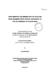
applications. These micro fibrils on reaction with strong acids break down into short<br />
crystalline rods or cellulose micro crystals [181].<br />
Figure 1.12 Morphology of the cellulose micro fibrils before (a) and after (b)<br />
silylation.<br />
[Ref: Gousse' H Chanzy., Cerradam.L., Fleury E., Polymer,(2004)45: 1569]<br />
45
Introduction<br />
<strong>Natural</strong> fibres, which are rich in cellulose, can be used as a starting material for the<br />
preparation of cellulose micro fibrils. Cellulose micro fibrils can be separated by<br />
methods like cryo-crushing where the frozen pulp is crushed with liquid nitrogen<br />
[182]. In addition, methods to mechanically homogenize and stabilize food<br />
ingredients could also be adopted for the preparation of cellulose micro fibrils [183].<br />
The morphology of the cellulose micro fibrils before and after silylation is given in<br />
Figure 1.12 a & b.<br />
Steam explosion is another excellent process which can be used to defibrillate the<br />
fibre bundles [184]. This method being fast and well controlled is well adapted for<br />
semi retted fibres. Enzymatic hydrolysis of cellulose is also accelerated by steam<br />
explosion. Grunert and Winter [185] developed cellulose nanocrystals from bacterial<br />
cellulose which are modified by trimethylsilynation. The untreated and the trimethyl<br />
silylated crystals were exploited as the particulate phase in nanocomposites with cross<br />
linked poly dimethyl siloxane as the matrix material. They found that these cellulose<br />
nanocrystals could be successfully incorporated into various polymer matrices for the<br />
preparation of nanocomposites. The untreated and surface silylated fibre samples<br />
consists of a random dispersion of long and rather stiff micro fibrils that occur<br />
individually or packed into bundles. The mild silylated micro fibrils, which had some<br />
morphological features as those of the untreated samples, were dispersible into non<br />
polar solvent to yield stable suspensions that did not flocculate. Gousse et al [186]<br />
developed micro fibrils from natural fibres and found that the silylated micro fibrils<br />
have acquired an inherent flexibility with the result that their suspensions present the<br />
rheological behaviour ofpolymer solutions.<br />
Cellulose based nano composites<br />
The concept of nanostructured material design is gaining widespread importance<br />
among the scientific community [187]. The strong reinforcement effects at low<br />
volume fraction resulted in tremendous interest from the industry and research circles.<br />
The concept of cellulose nanocomposites for load bearing applications is fairly new.<br />
46
Chapter 1<br />
Property enhancements are expected due to higher Young's modulus ofpure cellulose<br />
reinforcement and fmally distributed reinforcing microfibrils. A major problem in the<br />
commercial use of cellulose microfibrils in structural materials is the disintegration of<br />
cellulose from plant cell wall at reasonable cost and without severe degradation.<br />
Another major problem is dispersion of cellulose micro fibrils in a polymer matrix.<br />
Cellulose nanocomposites are usually fabricated by utilizing microfibrils of 10-50 nm<br />
on width as reinforcement in a polymer matrix. Although many studies provide<br />
detailed knowledge regarding the morphology and crystallography of different types<br />
of cellulose, the Young's modulus ofmicro fibrils from different sources and subjected<br />
to different types ofhydrolysis is seldom discussed. The research group at CERMAV<br />
CNRS has presented numerous studies based on cellulose whiskers reinforced<br />
nanocomposites [188]. Another area of interest is that of microfibrillated cellulose<br />
[MFC] nanocomposites. A review of the recent research into cellulose whiskers, their<br />
properties and their application in nanocomposite field has been presented by the<br />
same group [189]. Recently scientists achieved uniform pyrrole nanocoating on<br />
natural cellulose fibres without disrupting the hierarchical network structures of<br />
individual cellulose fibres by means of polymerization induced adsorption [190].<br />
Researchers have also reinforced natural rubber with naofibres of sepiolite [191]. The<br />
level of reinforcement was assessed from mechanical and orientation behaviour.<br />
Nanoscale modified plant structures such as paper or bast fibres also present a<br />
different approach to preparation of nanocomposites structures. An interesting study<br />
focusing on preserving the microfibril organization of wood veneer in composites was<br />
reported [192]. The basic idea was to increase the volume fraction of cellulose<br />
microfibrils by partially removing the lignin and hemicellulose wood polymers and by<br />
compressing the veneer. Phenol formaldehyde (PF) was used to preserve the<br />
compressed microstructure ofthe material and to bond micro fibrils. Researchers have<br />
looked into development of cellulose nano composites based on bacterial cellulose<br />
47
Introduction<br />
and cellulose acetate butyrate [193]. Bacterial or microbial cellulose have also found<br />
their way as reinforcement in composites [194]. Though the microbial cellulose<br />
composites have evoked widespread interest, the industrial use of microbial cellulose<br />
composites requires the development ofefficient arge scale fermentation technology.<br />
1.8 Green <strong>Composites</strong><br />
Significant research efforts are currently being spent in developing a new class of<br />
fully biodegradable green composites by combining natural fibres with biodegradable<br />
polymers [195-200]. These composites are environment friendly, fully degradable and<br />
sustainable. At the end of their life they can be easily disposed of or composted<br />
without harming the environment. The life cycle of a green composite is given in<br />
Figure 1.13. The green composite may be used effectively in many applications such<br />
as mass produced consumer goods with short life cycles of one or two years (non<br />
durable) or products indented for one term or short term (few times) use before<br />
disposal. A variety of natural and synthetic biodegradable resins are available for use<br />
in green composites. Most of 1hese resins degrade through enzymatic reactions when<br />
exposed to compost environment. Many will also degrade in moist outdoor<br />
environments through microbiallbacterial attack. A review of biocomposites<br />
highlighting recent studies and developments in natural fibres, biopolymers, and<br />
various surface modifications of natural fibres to improve fibre/matrix adhesion is<br />
presented by Mohanty et al [201]. Goda et al used ramie fibres in the form of low<br />
twist yarns and starch based resins to obtain green composites [202]. These<br />
composites had tensile strength in the range of 250 MPa and would be useful for<br />
structural applications. Mohanty et al [203] reported that plasticized polar cellulose<br />
acetate was found to be a better matrix for hemp fibre and thus exhibited improved<br />
physico mechanical properties. Incorporation of a high content of natural fibres of<br />
about 50% in the biocomposite system along with suitable surface modification of<br />
fibres and by the use ofcoupling agents can generate superior bio composites.<br />
48
1.9 Applications of short fibre reinforced rubber composites.<br />
Introduction<br />
<strong>Short</strong> fibres have the potential for reinforcing low performance tires.In automotive<br />
and truck tires they find application in better abrasion resistance for the chafer strip<br />
and in improved cut resistance to treads especially for trucks and OIR vehicles. As<br />
short fibres have higher green strength and cut, tear and puncture resistance they can<br />
be used for sheeting. Shot fibres can be utilized as the sole reinforcement for a<br />
moderate performance hose or as auxilIary reinforcement with cord constructions.<br />
They can provide stiffening to soft inner tubes for the application of metal braids and<br />
can extend hose life by bridging the stresses across weaker filaments. Other uses are<br />
belts diaphragms, gaskets, roofing, hoses, dock and ship fenders etc. <strong>Short</strong> fibres can<br />
reinforce and stiffen rubber in fenders and other impact applications in accordance<br />
with simpledesign equations.<br />
1.10 <strong>Isora</strong> fibre<br />
Various natural fibres like sisal, coir, jute, oil palm, bamboo etc have been proved to<br />
be a better reinforcement in rubber matrix. Incorporation of natural fibres resulted in<br />
better long term mechanical performance of elastomers. However studies on isora<br />
fibre as reinforcement have not yet been reported. <strong>Isora</strong> is a bast fibre presented in the<br />
bark of Helicteres isora plant. Two varieties ofthe plant are distinguished, tomentosa<br />
and glabrescens in which in the former the bottom side of the leaves is glabrous and<br />
in the latter both sides of the leaves are glabrous. The plant occurs as undergrowth<br />
especially as a secondary growth in forests. Seed sown during the rainy season easily<br />
propagates it. Roots stem and fruits of the plant are used for medicinal applications.<br />
The stem bark is exploited for the fibre. The best type of fibre is obtained when the<br />
plants are 1-1.5 years old; plants older than 2 years yield coarse and brittle fibre.<br />
Stalks can be harvested annually for fibre extraction from regenerated shoots. It<br />
occurs as undergrowth, especially as a secondary growth in forests. It coppices well<br />
shooting up rapidly when cut or burnt back. In some places the plant forms dense,<br />
almost impenetrable thickets covering large areas practically to the exclusion of other<br />
50
Chapter 1<br />
growths. The fibre which is present in the inner bark of the plant is polygonal in cross<br />
section with a circular or oval lumen. The cell wall of the fibre element is thick and<br />
lignified. The fibre is extracted from the stem by retting the stem in running water for<br />
18-24 days. The retted stalks were taken out of the water, beated gently with wooden<br />
mallets and fibres are peeled off, washed with water and dried. <strong>Fibre</strong> of good quality<br />
and colour is obtained when retting is effected in running water.<br />
Properties of natural fibres depend mainly on the nature and age of the plant, and the<br />
extraction method used. The data of production of isora fibre are not available.<br />
According to the estimate made in 1951 the yield of fibre is 50-60 md per acre [206].<br />
The fibre is used mostly for rough sacking or canvas and as cordage for sewing gunny<br />
bags and cattle harness. It is especially valued for container bags and used as pans in<br />
lever weighing systems. The quality of fibre is amenable to considerable<br />
improvement. By selecting stalks of equal age and maturity, and retting them under<br />
proper conditions and switching the dried fibre on suitable mechanical appliances, it is<br />
possible to obtain fibre which can be spun into good yarn and woven into canvas and<br />
other durable fabrics of excellent quality. Woven materials can be dyed and printed in<br />
attractive designs for making shopping bags. Ropes and cordages made of the fibre<br />
are better and smoother than coir products [207]. Stalks and twigs of the plant with<br />
and without bark are also suitable for the manufacture of writing or printing paper in<br />
combination with long fibre pulp of bamboo species [208]. Fruits disperse during<br />
April to June, and about 620 dried seeds weigh I Kg. The seeds sown during rainy<br />
season will germinate and grow without much care or other inputs. The total turn over<br />
of the dried fruits of the plant was about 1200 Kg in one year as recorded by Kerala<br />
state SC&ST Federation 1998. The cost of the seed was around Rs 1.50 per Kg [209].<br />
Certain quantity of seed collected from forest areas might have also gone to the<br />
general market, on which there is ID quantified data available.<br />
51
1.11 Scope and objectives of the present work<br />
Introduction<br />
The present work aims at investigating the prospect of using isora fibre as<br />
reinforcement in natural rubber matrix. Research work is going on with other natural<br />
fibres like jute, sisal, oil palm, banana, flax etc. In order to achieve this major<br />
objective several fundamental investigations on the fibre and its composites have been<br />
undertaken. Helicteres isora plant from which the fibre is separated is abundantly<br />
available in India especially in Kerala. Currently the fibre is being utilized for the<br />
preparation of ropes, cordages, gunny bags etc. These fibres if put to better use, as<br />
reinforcement in polymers will defmitely contribute to the development of the<br />
economy of the country and will open up new avenues for our natural resources. The<br />
factors which affect the properties of natural fibres are the cellulose content and<br />
microfibrillar angle. <strong>Isora</strong> fibre has relatively high cellulose content and a low micro<br />
fibrillar angle. These two are the desirable properties in a natural fibre to be used as<br />
reinforcement in polymer composites. Earlier reports have shown that the natural<br />
fibres are susceptible to moisture absorption, thermal degradation and biodegradation.<br />
Therefore strategies need to be worked out to overcome these limitations.For the<br />
successful design of a composite material from isora fibre and natural rubber several<br />
parameters like fibre aspect ratio, fibre orientation, chemical modification of the fibre<br />
surface, fibre matrix adhesion etc. that influences the performance of a short fibre<br />
composite have to be considered and to be optimized. Careful analysis ofthe literature<br />
indicates that no systematic studies have been reported about the use of isora fibre as<br />
reinforcement in polymers. The major attraction of this work is that both the matrix<br />
and the fibre are naturally available. Hence products based on this work will be both<br />
cheaper and sustainable.<br />
52
Chapter 1<br />
The following aspects of isora and isora /natural rubber composites are proposed<br />
to be evaluated<br />
(i) Separation and characterization ofisora fibre.<br />
Processing and evaluation of the physical and chemical properties of isora fibre is<br />
proposed to be done in detail. Chemical composition, surface morphology and thermal<br />
stability ofthe fibre are also proposed to be analyzed<br />
(ii) Chemical modification ofisora fibre surface for improved interaction with the<br />
polymer matrix.<br />
The polar natural fibre and non polar polymer matrix are likely to end up in relatively<br />
weak bonding. The bonding can be improved to an extent by varying the polarity of<br />
the fibre surface. Treatments with various chemical reagents like alkali, silane etc can<br />
be used effectively in order to change the surface polarity and thereby improve the<br />
fibre matrix interaction. In view of this, isora fibre surface is proposed to be modified<br />
by silane and alkali treatments. Effect of gamma radiation on the surface properties is<br />
also proposed to be investigated.<br />
(iii) Characterization ofthe modifiedfibre surface.<br />
Techniques like scanning electron microscopy, atomic force spectroscopy, and<br />
infrared spectroscopy are proposed to be tried characterize the untreated and treated<br />
fibre surface. The changes in crystallinty on chemical treatment are proposed to be<br />
studied by wide angle X- ray diffractometer. Changes in the mechanical performance<br />
of the fibres on various modifications are also proposed to be studied.<br />
(iv) Thermal degradation behaviour ofthe modifiedfibre.<br />
The examination of the thermal degradation behaviour of the untreated and treated<br />
fibre is proposed to be done by thermogravimeric and differential thermal analysis<br />
like TGIDTG, DSC, and DTA.<br />
53
(v) Preparation ofcomposites ofisora and natural rubber<br />
Introduction<br />
<strong>Fibre</strong> aspect ratio, fibre orientation, fibre loading and fibre matrix adhesion control the<br />
ultimate properties of the fibre rubber composites. <strong>Fibre</strong> length should not be too high<br />
so that individual fibres do not entangle or not too short so that effective reinforcing<br />
action will not be attained. So a critical aspect ratio for the fibre is proposed to be<br />
determined. <strong>Short</strong> fibre composite exhibit anisotropy in mechanical properties because<br />
of the preferential fibre orientation. Green strength measurements, mechanical<br />
properties and anisotropic swelling measurements are proposed to be used to estimate<br />
the extent of fibre orientation. A tricomponent bonding system and fibre surface<br />
modification is proposed to be used to produce better fibre matrix adhesion.<br />
(vi) Macroscale examination of the composites to evaluate the fibre matrix<br />
interaction.<br />
The mechanical properties of a composite are clear indication of the strength of the<br />
interface and thereby fibre matrix interaction. The fracture mechanism as evidenced<br />
by SEM and the value of strength characteristics point to the fibre matrix interaction.<br />
Therefore a comprehensive analysis of the macroscopic properties ofthe composite is<br />
proposed to be undertaken. The extent of interfacial adhesion between the fibre and<br />
rubber is also proposed to be analyzed by the restricted equilibrium swelling ID<br />
various solvents.<br />
(vii)<strong>Fibre</strong> breakage analysis.<br />
During processing fibres may undergo breakage hence analysis is also proposed to be<br />
made to evaluate the extent ofbreakage.<br />
(viii) Dynamic mechanical analysis.<br />
<strong>Fibre</strong> matrix interaction in composites has been studied in detail based on the response<br />
of the material when subjected to dynamic mechanical analysis. The nature of the<br />
damping curves and modulus curves are likely to be a good indication of the fibre<br />
matrix interaction and the nature ofthe interface.<br />
54
Chapter 1<br />
(ix) Ageing studies<br />
The degradation behaviour of isora/NR composites on exposure to gamma radiation,<br />
ozone and heat is proposed to be studied. The tensile properties of the unaged and<br />
aged samples will be compared. The effect of fibre matrix adhesion on ageing and<br />
tensile fracture mechanism of the aged composites is proposed to be studied using an<br />
optical microscope and scanning electron microscope,<br />
(x) Low temperature curing studies.<br />
At higher temperature fibre and rubber show a tendency to degrade. Hence a novel<br />
low temperature curing accelerator is also proposed to be tried and the properties of<br />
the composites cured at low temperature are proposed to be compared with that of the<br />
composites cured using conventional accelerator system.<br />
2. REFERENCES<br />
1. Encyclopedia ofPolymer Science Engineering, H.F. Mark<br />
Edition,JohnWiley and Sons, New York (1985)<br />
2. Tjong S.C.,Meng Y.Z., J Appl Polym Sci, (1999) 72: 501.<br />
3. Gonzalez P.I.,Yong R.J., J Mater s«,(1998) 33: 5715<br />
4. Thomas M.P., Winstone M. R., J Mater Sci ,(1998) 33: 5499<br />
5. Amash A., Zugenmaier P., Polymer Bulletin, (1998) 40:251<br />
6. Kishore., Venkatraaman S., J Appl Polym Sci, (1998) 67: 1565<br />
7. Raghavan J., Wool R. P., J Appl Polym Sci, (1999) 71: 775<br />
8. Oya N., Hamada H., J Mater Sci, (1998) 33: 3407.<br />
9. Srivastava V.K., Hogg p.J., J Mater Sci, (1998) 33: 1119.<br />
10. Zheng Q., Song Y.H.,Yi X.S., J Mater Sci Left, (1999)18: 35<br />
11. Leaity M.A., Smith P.A., Curtis P.T., <strong>Composites</strong>, (1992) 23: 387<br />
55
Introduction<br />
12. Richardson T., <strong>Composites</strong>-a design guide, Industrial Press Inc.,200<br />
Madison Avenue,Newyork,( 1987)<br />
13. Warner S.B., <strong>Fibre</strong> Science.,Prentice Hall,Engle wood Cliffs, New<br />
Jersey,( 1995)<br />
14. Mallick P.K., <strong>Fibre</strong> reinforced composite materials, manufacturing and<br />
design., Marcel Dekker,Inc., Newyork,( 1988) Ch. 1., p.I8<br />
15. Nielsen L.E., Mechanical properties ofPolymers and composites, Vol 1.<br />
Marcel Dekker (1974)<br />
16. Cook J.G., Hand book ofTextilefibres and <strong>Natural</strong>fibres, 4 th Edn.Morrow<br />
Publishing,England.( 1968).<br />
17. Rubin 1.1, Plastics Materials Technology, Wiley Interscience, (1990)<br />
18. Milewski J.V., Katz H.S., Handbook ofReinforcementsfor Plastics,Van<br />
Nostrand Reinhold (1987<br />
19. Gachter R., Muller H., Plastics Additives Handbook, Hanser Publishers<br />
(1990)<br />
20. Sathyanarayana K.G., Kulkarni A.G., Rohtgi p.k., J Scientific and Industrial<br />
Res,(1983) 42: 425<br />
21. Payen A., Hebd C.R., Seances Acad Set, (1938) 7: 1052<br />
22. Woodcock C., Sarko A., Macromolecules.ci'rsiv; 13: 1183<br />
23. Sarko A., Muggli R., ibid ,(1974) 7: 480.<br />
24. Kritschewsky G.E.,ChemischeTechnology Von Textilmaterialien, Moskau,<br />
Legprombitisdat(1985).<br />
25. Ammalahti E., Brunow G., Robert D., J Agri Food Chem,(1998) 46: 5113<br />
26. Xiao B., Sun X.F., Sun R.C., Polym Deg Stab,(2001) 74: 307.<br />
27. Bledzki A.K., Gassan J., Prog Polym Sci ,(1999) 24: 221<br />
28. Hill S., New Scientist (1997) p 36<br />
29. Satyanarayana K.G., Pillai S.G.K., Handbook ofCeramics and Composite<br />
56
Chapter 1<br />
CheremisinoffN.P., Edition Marcel Dekkar, New York Vol 1 (1990).<br />
30. The Wealth ofIndia - A Dictionary ofIndian Raw materials and Industrial<br />
products., Published by CSIR, New IXlhi (1959) 5: 27-29.<br />
31. Wright J.R., Mathias L.l, J Appl Polym Sci, (1993) 48: 2241.<br />
32. Hednberg P., Gateholm P., J Appl Polym Set, (1995)56: 641.<br />
33. Maldas D., Kokta B.V., J Comp Mater, (1991) 25: 375.<br />
34. Maldas D.,Kokta B.V., Polym Plast Technol, Eng,(1990) 29: 419.<br />
35. Prasanth kumar R., Thomas S., Bull Mater Sci, (1995) 18(8): 1021.<br />
36. Geethamma V.G., Mathew K.T., Thomas S., Polymer, (1998) 39: 1483<br />
37. Ismail H., Rosnah N., Rozman H.D., Polymer, (1997) 38(16): 4059.<br />
38. Ismail H., Shuhelmy S., Edyham M.R., Ellr Polym J ,(2002) 38: 39<br />
39. Harikumar K.R., Joseph K., Thomas S.,JReinfplast Comp, (1999) 18: 346.<br />
40. Yamini S.A.K., Ahmad A.J.,Nasir N.M, Proc. ofInt Symposium on Blo<br />
<strong>Composites</strong> and Blends based on naturalfibres. (1994) p.135<br />
41. Rowel R.M., Banks W.B., Gen. Teeh.Rep.FPL-GTR-50; USDA Forest<br />
service, Forest Products Laboratory, Madison, WI (1985) 24<br />
42. Feughelman M., Nordan P.J., J Appl Polym Sei, (1962) 6: 670.<br />
43. Joly C., Gauthier R., Coubles E.S., J Appl Polym Sci, (1996) 61: 57.<br />
44. Schniewind A.P., Wood and fire, M.B. Bever (ed), Encyclopedia of<br />
Materials Science and Engineering, Vol.7, l" edition, Pergamon<br />
Press,Oxford (1986).<br />
45. Shukry N., Girgis B.S., Polym Plast Technol Eng, (1992) 31: 541.<br />
46. Beall F.C., Thermal degradation of wood, M.B. Bever (ed), Encyclopedia 0.1'<br />
Materials Science and Engineering, Vol.7, 1st edition, Pergamon Press,<br />
Oxford (1986).<br />
47. Tinh N., Eugene Z., Edward M.B., J Maeromol Sci, (1981) C20 : 1<br />
48. Tinh N., Eugene Z., Edward M.B., J Macromol Sei, (1981) C21 : 1<br />
57
Chapter1<br />
72. Khalil H.P., Ismail H., Rozman H.D., Europ Polym J, (2001) 37: 1037<br />
73. Mani P., Satyanarayan K.G., J Adhesion Sci Technol, (1990) 4: 17.<br />
74. Liao B., Huang Y., Cong G., J Appl Polym Sci, (1997) 66: 1561.<br />
75. Rowell RM., ACS Proceedings,PolymMater Sci Eng, (1992) 67: 461.<br />
76. Rowell R.M., Clemson C.M, Proceedings ofthe 2(Jh International particle<br />
board/<strong>Composites</strong>Symposium, WA, (1992) 251.<br />
77. Bledzki A.K., Gassan J., J Appl Polym Sci, (1996) 59: 1329.<br />
78. Mohanty A.K, Singh B.C., J Appl Polym Sci, (1987) 34: 1325.<br />
79. Muzumdar P., Sanyal S., Dasgupta b., Indial J <strong>Fibre</strong> Technol, (1994) 18:<br />
286.<br />
80. Anderson M., Tillman A.M., J Appl Polym Sci, (1989) 37: 3437.<br />
81. Sahoo P.K., Samantaray H.S., Samal RK., J Appl Polym Sci, (1986) 32:<br />
5693<br />
82. Samantaray H.S., Samal R.K., J Appl Polym Sci, (1986) 37: 3085.<br />
83. Mannan-Kh M.,Latifa B, Polymer, (1980) 21: 777.<br />
84. Huque M.M., Habibuddowla M.D., Mohamood A.J., J Polym Sci, Polym<br />
Chem Ed, (1980) 18:1447.<br />
85. Samantaray H.S., Samal R.K.,JMacromol Sci, Macromol Chem Phy,<br />
(1986) C26:81.<br />
86. Lu J.Z., Wu Q., Negulescu 1.1., J Appl Polym Sci, (2005) 96: 93.<br />
87. Thielemans W., Wool R.P., Comp Part A, (2004) 35: 327.<br />
88. Harper D., Wolcott M., Comp Part A, (2004) 35: 385.<br />
89. Abdulmouleh M., Bou S., Duarte A.P., Inter J Adhesion, (2004) 24:43.<br />
90. Hemandez E.G., Claverie A.L., Polym Comp, (2004) 25(2): 34.<br />
91. Lu J.Z., Wu Q., Negulescu 1.1., CompInterfaces, (2005) 12(1):125.<br />
92. Saheb D.N., Jog J.P., Advances in Polym Technol, (1999) 18: 351<br />
93. Pedro J., Mamiel De H.F., Vega J.A., J Appl Polym Sci,(1997) 21: 197<br />
59
Introduction<br />
94. Mohd Ishak Z.A., Aminullah A., IsmailH, Rozman H.D.,JAppl Polym Sci,<br />
(1998) 68:2189.<br />
95. Ismail H., Shuhelmy M.R., Euro Polym J, (2002) 38: 39.<br />
96. Krysztatkiewicz A., Domka L., Plast Rubb Proc Appl, (1986) 6: 197<br />
97. Mwaikambo L.Y., Ansell M.P., J Appl Polym Sci, (2002) 84:2168.<br />
98. Gassan J., Bledzki A.K., Comp Sci Technol, (1999)59:1303.<br />
99. Bisanda E.T.N., Ansell M.P., Comp Sci Technol, (1991) 41:165.<br />
100. Aziz S.H., Ansell M.P., Comp Sci Technol, (2004) 64:1219.<br />
101. Samal R.K., Rout S.K., Mohanty M., J Polym Mater, (1995) 12: 229.<br />
102. Hill C.A.S., Akhalil H.P., J Polym Sci, (2000) 78: 1685.<br />
103. George J., Bhagawan S.S., Thomas S., Comp Interfaces, (1998) 5: 201.<br />
104. Sreekala M.S.,Joseph R., Thomas S., App Comp Mater, (2000) 7: 295<br />
105. Mohanty A.k., Khan M.A., Comp Sci Technol, (2000) 60: 1115.<br />
106. Calado V., Barreto D.W., Almeida J.R.M., Polym Comp, (2003) 2:1.<br />
107. RozmanH.D., KwnarR.N., Ismail H., EuroPolymJ,(2000) 36: 1483.<br />
108. Prasanth kumar R, Thomas S., PolymInternational, (1995) 38(2): 173.<br />
109. Geethamma V.G, Thomas S., Int J Polym Mater, (1996) 32: 147.<br />
110. Sreekala M.S., Thomas S., Comp Sci Technol, (2003) 63: 861.<br />
111. Joseph P.V., Joseph K., Thomas S., Comp Sci Technol, (2002) 62: 1357.<br />
112. George J., Bhagawan S.S., Thomas S., Comp Sci Technol, (1998) 58:1471.<br />
113. Pothen L.A.,Neelakandan N.R.,Thomas S., J ReinfPlast, (1997) 16: 8<br />
114. Rogers J.W., <strong>Rubber</strong> World, (1981) 27: 183.<br />
115. Goettler l.A., Lambright A.J.,Leib R.I., Rubb Chem Technol ,(1981) 54: 277.<br />
116. Abrate S., Rubb Chem. Technol, (1986) 59: 384.<br />
117. Chakraborthy S.K., Setua D.K., De S.K., Rubb Chem Technol, (1982)<br />
55:1286.<br />
118. Moghe S.R., Rubb Chem Technol, (1974) 47: 1074.<br />
60
Chapter1<br />
119. VincentJ.F.V Appl Comp Mater, (2000) 7: 269.<br />
120. Boustany K., Coran Y., US Patent No.33 679 364 (1972)<br />
121. DunnomD.D., Wagner M.P., Derringer G.C., ChemicalDivision, PPG<br />
Industries Inc., US Patent No.3746669 (1973).<br />
122. DerrigerD.C., <strong>Rubber</strong> World, (1971) 45: 165.<br />
123. Broutman L.j., Aggarwal B.D., Analysis and performance offibre<br />
composites, Soc.Plast. Ind., John Wiley and Sons,Newyork (1980)<br />
124. Monette L., AndersonM.P., GrestG.S., Polym Comp, (1993) 14(2): 101.<br />
125. TermoniaY., J Mater Sci Lett, (1993) 12: 732.<br />
126. Rosen B.W.,<strong>Fibre</strong> Composite Materials, American Society for metals,<br />
Metal Park, Ohio (1965)<br />
127. O'Connor J.E., <strong>Rubber</strong> Chem Technol, (1977) 50: 945.<br />
128. MurthyV.M., BhowmickA.K., De S.K., J Mater Sci, (1982) 17: 709.<br />
129. SetuaD.K., De S.K., Rubb Chem Techno, (1983) 56: 808.<br />
130. Chakraborty S.K., Setua D.K., De S.K., Rubb Chem Technol, (1982) 55:<br />
1286.<br />
131. SetuaD.K., De S.K., J Mater Sci, (1984) 19: 983.<br />
132. Broutman L.J., Aggarwal B.D., Analysis and performance offibre<br />
composites, Soc.Plast. Ind., John Wiley and Sons,Newyork (1980)<br />
133. O'Connar J.E., Rubb Chem Technol, (1974) 47: 396.<br />
134. Boustany K.., Arnold R. L., J Elasto Plast, (1976) 8: 160.<br />
135. Boustany K., Coran A.Y., US Patent No. 3 397 364 ,to Monsanto C (1972)<br />
136. MurthyV.M., De S.K., J Appl Polym Sci, (1982) 27: 4611.<br />
137. MurthyV.M., De S.K., J Appl Polym Sci, (1984) 29: 1355<br />
138. Ibarra L., ChamorroA.C., J Appl Polym Sci, (1991) 43: 1805.<br />
139. Rueda L.I., ChamorroA.C., J Appl Polym Sci, (1989)37: 1197.<br />
140. GoettlerL.A., Lambright A.J.,Leib R.I., Rubb Chem Technol ,(1979) 52: 838<br />
61
Introduction<br />
141. Geethamma V.G., Joseph R., Thomas S., J Appl Polym Sci, (1995) 55: 583.<br />
142. Varghese S., Kuriakose B., Thomas S., Ind J Nat Rubb Res, (1992) 5(1):18<br />
143. Joseph K., Thomas S., Mater Lett,(1992) 15: 224<br />
144. Prasanth Kumar R., Thomas S., J Appl Polym Sci, (1995) 58: 597.<br />
145. Kutty S.K.N., Nando G.B., J Appl Polym Sci, (1991) 43: 1913.<br />
146. Roy D., Bhowmick A.K., De S.K., Polym Eng Sci, (1992) 32: 971.<br />
147. Senapati A.K., Nando G.B., Int J Polym Mater, (1988) 12: 73.<br />
148. Senapati A.K., Nando G.B., Kutty S.K.N., Int J Polym Mater, (1989) 12:<br />
203<br />
149. Kutty S.K.N., Nando G.B., J Appl Poym Sci, (1991) 43: 1913.<br />
150. Varghese S., Kuriakose B., Thomas S., J Adhes Sci Technol,(1994) 8:235<br />
151. Geethamma V.G., Thomas S., Int J Polym Mater, (1996) 32: 147.<br />
152. Prasanth Kumar R., Thomas S.,Bull Mater Sci,(1995) 18(8) :1021<br />
153. Arumugham N., Tamaraselvy K.,J Appl Polym Sci, (1989)37: 2645<br />
154. Ismail H., EdyhamM.R., Wirjosentono B., Polymer Testing, (2002) 21:139.<br />
155. Derringer D.C., J Elast Plast, «1971) 3:230<br />
156. Chawla K.K., Composite Materials, Spriger Verlarg,Newyork(1987)<br />
157. Richardson M.O.W., Polymer Engineeringcomposites, Applied Science<br />
Publishers,London (1977) p. 1<br />
158. Anthonie G., Arnol R.L., Boustany K., Eur Rubb J, (1975) 157: 28.<br />
159. Hamed P., Coran A.Y., Additives for Plastics, Seymour Edn. Academic<br />
Press,Newyork (1982)<br />
160. Murthy V.M., De S.K., J Appl Polym Sci,(1984) 29: 1355<br />
161. Varghese S., Kuriakose B., Thomas S., <strong>Rubber</strong> Chem. Technol, (1997)63:<br />
550.<br />
162. Ismail H., Rozman H.D., Ishiaku V.S., Polym International, (1997) 43: 23.<br />
163. Geethamma V.G., Joseph R. Thomas S., Polymer, (1998) 39: 1483.<br />
62
Chapter 1<br />
164. Das B., J Appl Polym Sci, (1973) 17: 1019.<br />
165. Hartikainen J., Hine P., Friedrich K., Comp Sci Technol, (2005) 65: 257.<br />
166. ldicula M., Neelakandan N.R., Thomas S., Oommen S., Joseph K., J Appl<br />
Polym Sci, (2005) 96 : 1699<br />
167. Idicula M., Malhotra S.k., Thomas S., CompSci Technol, (2005) 65:106.<br />
168. Kalaprasad G., Joseph K., Thomas S., J Comp Mater, (1997) 31: 509.<br />
169. Mishra S., Comp Sci Technol, (2003) 63: 1377.<br />
170. Rozman H.D., Ismail H., Euro PolymJ, (2001) 37:1283.<br />
171. Junior C.Z.P., Fonseca V.M., Monteiro S.N., Polymer Testing, (2004)<br />
23:131.<br />
172. Rout J., Misra M., Tripathy S.S., Mohanty A.K., Comp Sci Technol, (2001)<br />
61: 1303.<br />
173. Sreekala M.S., Neelakandan N.R., Thomas S., J Polym Eng, (1997) 16: 265.<br />
174. Maya Jacob, Varghese K.T., Comp Sci Technol, (2004) 64: 955.<br />
175. Haseena A.P., Unnikrishnan G., Thomas S., Comp Interf, (2004) 11(7):489.<br />
176. Malainine M.E., Dufresne A., Mahrouz M., Comp Sci Technol, (2005)65:<br />
520.<br />
177. Gousse H Chanzy., Cerrada M.L., Fleury E., Polymer, (2004) 45: 1569<br />
178. Okubo K., Fujii T., Yamamoto Y., Comp Part A, (2004) 35: 377<br />
179. Turbak A.F., Snyder F.W., Sandberg K.R., Appl Polym Sci, Appl Polym<br />
Symp,(1983) 37: 815<br />
180. Weibel M.K., U.S.Patent 4 831127 SBP Inc. (1989).<br />
181. Dufresne A., Cavaille J.Y., Vignon M.R., J Appl Polym Sci, (1997) 64:<br />
1185.<br />
182. Dufresne A., Dupeyre D., Vignon M.R., J Appl Polym Sci, (2000) 76: 2080.<br />
183. Turbak A.F., Snyder F.W., Sandberg K.R., U.S.Patent 4.374.702 (1983)<br />
184. Okubo K., Fujii T., Yamamoto Y., CompPart A, (2004) 35: 377.<br />
63
2.1<br />
2.2<br />
2.3<br />
2.4<br />
2.5<br />
2.6<br />
2.7<br />
2.8<br />
CHAPTER 2<br />
oMATEORlALSAND oEXPERolMENTAL TECHNIQUES<br />
2.4.1<br />
2.4.2<br />
2.5.1<br />
2.5.2<br />
2.5.3<br />
2.5.4<br />
2.5.5<br />
2.5.6<br />
2.5.7<br />
2.5.8<br />
2.5.9<br />
2.5.10<br />
2.6.1<br />
2.6.2<br />
Materials<br />
Chemical composition ofisora fibre<br />
<strong>Fibre</strong> preparation and surface modification<br />
Preparation of composites and test specimens.<br />
Cure characterstics ofthe rubber compounds.<br />
Moulding ofthe test specimens.<br />
Characterisation offibre and composites<br />
Scanning electron microscopy.<br />
Atomic Force Microscopic measurements and Image analysis<br />
lnfraredspectroscopy<br />
Optical microscopy<br />
Integrated coupled plasma -atomic emission spectroscopy<br />
Thermal Analysis<br />
Wide angle x ray diffraction studies<br />
<strong>Fibre</strong> breakage analysis<br />
Mechanical property measurements<br />
Green strength measurements<br />
Swelling studies<br />
Swelling data analysis<br />
Swelling parameters<br />
Ageing studies<br />
References
Abstract<br />
Materials and experimental techniques<br />
.MA"lE.MALS AND .EXPERIMENTAL TECHNIQUES<br />
CHAPTER1<br />
This chapter gives a briefdescription ofthe materials and methods used for<br />
the preparation ofcomposites. The chemicals used for various fibre treatments have<br />
also been discussed. A briefdescription about the different analytical techniques used<br />
for the characterization offibres and composites are also given in this chapter.<br />
66
Chapter 2<br />
2.1 MATERIALS<br />
2.1.1 <strong>Isora</strong> fibre.<br />
<strong>Isora</strong> fibre was separated from the bark ofHelicteres isora plant by retting in water.for<br />
18-24 days. The average length ofthe fibre is approximately 75-100 cm. The physical<br />
and chemical characteristics ofisora fibre is discussed in Chapter 3 and are already<br />
reported else where [1]<br />
2.1.2 <strong>Natural</strong> <strong>Rubber</strong><br />
<strong>Natural</strong> rubber used for the study was ISNR 5(light colour) grade obtained from<br />
<strong>Rubber</strong> Research Institute of India, Kottayam, Kerala. The molecular weight,<br />
molecular weight distribution and non rubber constituents of natural rubber are<br />
affected by clonal variation, season and methods of preparation [2]. Hence rubber<br />
obtained from same lot has been used in this study. Its properties are given in table 2.1<br />
Table 2.1 Properties of natural rubber [3]<br />
Dirt content % by mass<br />
Volatile matter % by mass<br />
Nitrogen % by mass<br />
Ash % by mass<br />
Initial plasticity number.Ps<br />
Plasticity retention index PRI<br />
2.1.3 Compounding ingredients<br />
0.03<br />
0.50<br />
0.30<br />
0.40<br />
38<br />
a) Cross linking agent: sulphur (9 =2.05) supplied by Mls Standard chemical<br />
company Pvt. Ltd Madras.<br />
b) Accelarators: CBS (N cyclohexyl benzothiazyl sulphanamide f =1.30) and ZDC<br />
(zinc diethyl dithiocarbamate f =1.47) supplied by ICI India Ltd Calcutta, TMTD<br />
(tetra methyl thiuram disulphide '=1.3) supplied by polyolefins Industries<br />
67<br />
78
Chapter 2<br />
a. Mercerization. <strong>Fibre</strong>s of average length 10 mm were immersed in 5% NaOH<br />
solution for different time intervals viz; 4, 24,48and 72 hrs both at room temperature<br />
and at boiling temperature (95°C). Finally the fibres were repeatedly washed with<br />
water containing little acetic acid and then dried in an air oven at about 70°C for 24<br />
hrs.<br />
Mercerization is one of the oldest methods proposed by John Mercer in 1842 which<br />
has been used for treating natural fibres [4]. The process involves the conversion of<br />
native cellulose (cellulose1) into cellulose 11, when the former is swelled in NaOH<br />
followed by the removal of alkali by washing with water. This process causes<br />
significant changes in the molecular orientation, crystal structure and degree of<br />
crystallinity and morphology of the fibres [5]. This led to the formation of more<br />
flexible micro fibirils than that present in the native cellulose due to the less<br />
crystallinty in the the resulting cellulose IT. The natural impurities are also removed<br />
from the surface as a result of mercerization. There are three chemically active -OH<br />
groups on each anhydro glucose units of the untreated cellulose. Even though these<br />
groups are not much reactive under normal conditions, these become more reactive on<br />
mercerization.<br />
b. Gamma irradiation. <strong>Isora</strong> fibres are exposed to "rays from 6OCO source at a dose<br />
rate of O.IMrad per hr for different time intervals depending upon the dosage of<br />
radiation.<br />
c. Silane treatment. Alkali treated fibres were dipped in alcohol/water mixture (60:40)<br />
containing 1% vinyl triethoxy silane coupling agent. The pH of the solution was<br />
maintained between 3.5 and 4. <strong>Fibre</strong>s were washed in distilled water and dried<br />
2.4 Preparation of composites and test specimens.<br />
The fibre was mxed with rubber on a laboratory two roll mixing mill with size 150 X<br />
300 mm as per ASTM D 3184-80 at a friction ratio of 1:1.25. The mill opening was<br />
69
Materials and experimental techniques<br />
set at 0.2mm. The base formulation of the rubber compound is given in Table 2.2 and<br />
the description of the mixes is given in different tables along with the respective<br />
analyses in various chapters. The rubber was first masticated by careful control of<br />
temperature, nipgap, time and uniform cutting operation. The nip gap, mill roll speed<br />
ratio and number of passes were kept the same in all mixes. The compounding<br />
ingredients were added in the following order given in Table 2.2.<br />
Table 2.2 Basic formulation of the rubber compound.<br />
Ingredients Parts per hundred rubber[phr]<br />
<strong>Natural</strong> rubber 100<br />
ZnO 5.0<br />
Stearic acid 2.0<br />
TDQ 1.0<br />
CBS 0.6<br />
TMTD 0.1<br />
Sulphur 2.5<br />
RF resin Variable<br />
Hexa Variable<br />
Silica Variable<br />
<strong>Fibre</strong> untreated Variable<br />
<strong>Fibre</strong> treated Variable<br />
The fibres were incorporated at the end of the mixing process, to avoid breakage of<br />
fibres taking care to maintain the direction of compound flow, so that majority of<br />
fibres are aligned in the grain direction. The samples were milled for sufficient time to<br />
disperse the fibres in the matrix at a mill opening of 1.25 mm. the stock was sheeted<br />
out after complete mixing. The homogenization was done by passing the rolled ssheet<br />
70
2.4.1 Cure characterstics of the rubber compounds.<br />
Materials and experimental techniques<br />
Goettfert elastograph model 67.85 was used for the determination of the cure<br />
characteristics of the mixes. It uses two directly heated, opposed biconical discs that<br />
are designed to achieve a constant shear gradient over the entire sample chamber. The<br />
specimen was kept in a lower die, which is oscillated through a small deformation<br />
angle (+/-O.t» at a frequency of 50 oscillations per minute. The torque transducer on<br />
the upper die senses the force being transmitted through rubber.<br />
Minimum torque (Md: the torque obtained by the mix after homogenizing at the test<br />
temperature, the onset ofcure.<br />
Maximum torque (MHJ: Torque recorded after the curing ofthe mix is completed<br />
Optimum cure time (190): It is the time taken to attain 90°A, of the maximum tome<br />
Scorch time (tlO): It is the time taken to attain 10% ofthe maximum torque.<br />
2.4.2 Moulding of the test specimens.<br />
The test specimens for determining the physical properties were prepared in standard<br />
moulds by compression moulding on an electrically heated hydraulic press having 18<br />
X 18 inch platens at a pressure ofof 200 kg/crrr on the mould. The rubber compounds<br />
were vulcanized upto their their respective cure times at 150°C.Moulding were cooled<br />
quickly in water at the end of the curing cycle and stored in a cool and dark place for<br />
24 hrs and were used for subsequent physical tests. For smpls having thickness more<br />
than 6mm (compression set, abrasion resistance etc ;) additional time based on the<br />
sample thickness was given to obtain satisfactory mouldings.<br />
2.5 Characterisation of fibre and composites<br />
2.5.1 Scanning electron microscopy.<br />
The SEM photograph of the fibre surfaces and cross section of the untreated and<br />
treated fibres and fracture surfaces of the composites were taken using JEOL 35C<br />
Model scanning electron microscope. The principle ofwhich was detailed by Johar<br />
72
Chapter 2<br />
et al [7]. The fracture surfaces of the composites were carefully cut from the failed<br />
test specimens without touching the surface. To avoid electron charging effects,<br />
samples were sputter coated with gold within 24 hrs in a polaron SEM coating unit se<br />
515. The fractured specimens and gold coated samples were stored in a descicator till<br />
SEM observations were made. The SEM photographs of the fractured surfaces will<br />
give information regarding fracture mechanism and interface adhesion of the<br />
composites.<br />
2.5.2 Atomic Force Microscopic measurements and Image analysis<br />
The AFM images ofthe untreated and chemically modified fibres were recorded with<br />
a Nanoscope Illa SPM (Digital Instruments, Santa Barbara, CA) equipped with an<br />
extender electronics module that enables phase imaging in the tapping mode. All the<br />
images were recorded in tapping mode using silicon cantilevers with a resonance<br />
frequency between 265 and 400 kHz. The scan rate was 1.0-1.25 Hz. The Scanning<br />
Probe Image Processor (SPIP, Image Metrology, Denmark) was used for the<br />
roughness analysis ofthe images.<br />
2.5.3 Infrared spectroscopy<br />
Infrared spectra of raw and chemically modified isora fibre were obtained with<br />
Schimadzu model IR 470 infrared spectrophotometer, Scimadzu, Japan by using solid<br />
KBr pellet technique. <strong>Fibre</strong> samples were cut into small pieces and grounded well<br />
before mixing it with KBr.<br />
2.5.4 Optical microscopy<br />
An optical stereo microscope of Leitz metallux 3, Germany was used for calculating<br />
fibre length distribution in NR matrix and also for observing the equilibrium swelling<br />
behaviour of the composites.The crack developd on the samples after ozone ageing<br />
was also observed by optical microscope.<br />
73
Materials and experimental techniques<br />
and elongation at break were measured according to ASTM D 412-87(method A).<br />
Dum bell shaped specimens were punched out ofthe moulded sheet and tests were<br />
carried out both along and across the grain direction. Tensile strength is reported in M<br />
Pa and Elongation break is reported in percentage (Conversion factor is 1<br />
MPa=10.197 Kg/cm'
2.6.1. Swelling data analysis.<br />
(i) Measurement ofadhesion<br />
Materials and experimental techniques<br />
The extent of adhesion between fibre and rubber can be evaluated by measuring the<br />
volume fraction of rubber in the swollen and unswollen sample. In order to determine<br />
the volume fraction of the unswollen sample the test specimen was weighed both in<br />
air and water. The difference between the two weights gave the volume of the<br />
samples. Using the base formulation, the amount of rubber present in the weighed<br />
sample of each specimen and its volume were calculated. From these data the volume<br />
fraction ofrubber present in dry specimen was calculated and is denoted as Vi.<br />
The volume fraction ofrubber in the swollen sample Vi was calculated by the<br />
expression<br />
Vr [(D-FT)/ (fr)] (2.3)<br />
[CD-FT) /
Materials and experimental techniques<br />
100°C for 3 and 5 days. Ozone resistance was determined according to ASTM D 518<br />
method B. Samples were exposed to ozonised air in an ozone chamber (MAST Model<br />
700-1) for 36 hrs. The concentration of ozone was maintained at 50 pphm and the<br />
inside temperature at 40°C. The ozone cracks developed on the samples were analyzed<br />
by optical microscopy. For radiation ageing, the samples were irradiated with gamma<br />
rays from 60eo source at a dose rate of 0.3413 Mrad /hr.in a gamma chamber. Tensile<br />
and tear testing before and after irradiation and thermal ageing were carried out<br />
according to ASTM D 412-86 and D 624-87standards.<br />
80
Chapter 2<br />
2.8 REFERENCES<br />
1. Lovely M., Joseph K.D., Rani J., Advances ofEco materials, thInternational<br />
conference on Eco materials, Stallion press, Singapore, (2005) Vol. 2 Page 449.<br />
2. Subramanyam A., Rubb Chem. Technol, (1972) 45: 346.<br />
3. Subramanyam A., Proc R.R.I.M, Planters conference, Kaulalumpur (1971) 252.<br />
4. Allen G.,(Ed.), Comprehensive polymer Science- Polymer reactions, Pergamon<br />
Press, (1989) 6.<br />
5. Anon J., Tex Res J (1898) 59: 772.<br />
6. Blackley D.C., Polymer Lattices, Chapman & hall Publishers, London, Second<br />
Ed. (1997) 3: 515.<br />
7. Johari 0., SamudraA.V., Characterisation ofsolid surface, Kane P.F., Larrabe<br />
G.B., Eds, Plenum Press, Newyork,(1974) Ch. 5.<br />
8. Aithal V.S., Aminabhavi T.M., J Chem Edn, (1990) 67(1): 82.<br />
9. Hargopad S.B., Aminabhavi T.M., J Appl Polym Sci, (1991) 42: 2329.<br />
81
3.1<br />
3.2<br />
3.3<br />
3.4<br />
3.5<br />
3.2.1<br />
3.2.2<br />
3.2.3<br />
3.2.4<br />
3.2.5<br />
3.2.6<br />
ISO'RA .F1B·RES: CRARACTERlZATION<br />
Introduction<br />
Results and Discussion<br />
Chemical analysis<br />
Mechanical properties<br />
Morphological analysis<br />
Chemical modifications: IR Spectroscopy<br />
Thermal studies<br />
Wide angle X ray diffractometer studies<br />
Theoretical Prediction ofMicro fibrillar angle and Strength ofthe<br />
fibre<br />
Conclusions<br />
References
3.1 I:\TRODlJCTION<br />
!SOfU fibres: characterization<br />
ISOR..\ is a natural fibre present in the bark of Helicteres isora plant. [East Indian<br />
screw tree]. The plant belongs to the Sterculiacea family and found in the warmer<br />
parts of the world. Four species were reported to occur in India of which Helicteres<br />
isora has attained importance as a source of fibre.] 1] The plant occurs often<br />
gregariously, throughout India. <strong>Fibre</strong> is extracted from the bark of the plant by retting<br />
it in water for three weeks. <strong>Fibre</strong>s of good colour and quality were obtained when<br />
retting is effected in running water. <strong>Isora</strong> fibre is pale yellow in colour, soft. silky and<br />
lustrous which resembles jute in appearance, with comparable strength and durability.<br />
The photograph of raw fibre is given in Figure 3.1<br />
Figure 3.1 Photograph of isora fibre<br />
The root, stem, leaves and fruits of the plant are used for medicinal purposes. The<br />
stem, leaves, fruits and the dried seeds are given in Figure 3.2.<br />
84
Chapter 3<br />
(a) (b)<br />
(c) (d)<br />
Figure 3.2 Helicteres isora plant (a) leaves, (b) fruit, (c) stem<br />
(d) dried seed<br />
85
<strong>Isora</strong> fibres: characterization<br />
Recently we have reported the possibilities of using isora fibre as a potential<br />
reinforcement in natural rubber and polyesters [2-3]. The mechanical properties of<br />
these matrices are greatly improved by incorporation of this fibre. The resultant<br />
composite product will be a cost effective and value added material for various<br />
products like conveyor belts, power transmission belts etc. Use of biodegradable<br />
matrix and natural fibres as reinforcement has open new potential applications to these<br />
composites as they are eco friendly materials. The physical properties of other natural<br />
fibres have already been reported [4-9].To date no systematic work las been reported<br />
to be undertaken to study the properties of isora fibre.<br />
This paper reports the physical, chemical, mechanical, thermal and morphological<br />
characteristics of isora fibre. Chemical analysis of isora fibre shows that major<br />
chemical component present is cellulose. The cellulose content plays an important<br />
role in the mechanical performance of the fibre. Mechanical properties such as tensile<br />
strength, Young's modulus, and elongation at break were evaluated. Various surface<br />
modifications of the fibre by alkali and silane treatment and gamma irradiation have<br />
been tried. TGA, DTG, DTA and DSC were carried out to study the thermal stability<br />
ofthe fibre. The morphological analysis has been carried out by using SEM and AFM.<br />
The crystallinity and the chemical reactivity of the fibre were evaluated by using<br />
WAXRD and IR. Micro fibrillar angle and the strength of the fibre were theoretically<br />
calculated.<br />
3. 2 RESULTS AND DISCUSSION<br />
3. 2. 1 Chemical Analysis<br />
Table 3.1 shows the various chemical components jresent in the isora fibre and the<br />
solubility of the fibre in different solvents.<br />
86
Chapter 3<br />
Table 3.1 Chemical constituents of<strong>Isora</strong> fibre<br />
Chemical constituents Solubility in various solvents<br />
(%) (%)<br />
Cellulose 74.8 Alcohol-benzene 6.3<br />
Lignin 23.0 Ether 5.7<br />
Ash 0.92 1% caustic soda 14<br />
Fat 1.09 Cold water 10<br />
Moisture content 5-6 Hot water 12<br />
Ca(ppm) 713.45 Acetone 5.6<br />
Mg(ppm) 37.93<br />
Fe(ppm) 16.10<br />
K(ppm) 10.54<br />
Na(ppm) 10.42<br />
From Table 3.1 it is clear that isora is a cellulose rich fibre with comparatively low<br />
lignin content, which contributes to better performance ofthe fibre as reinforcement in<br />
polymers. The fme structure of cellulose materials is composed of crystalline and<br />
amorphous regions. The amorphous regions easily absorb chemicals such as dyes and<br />
resins whereas the compactness of the crystalline regions makes it difficult for<br />
chemical penetration. The fibre is hygroscopic and its moisture content is found to be<br />
5-6%. From table 3.1 it is clear that the fibre contains about 12% water soluble<br />
materials.<br />
3. 2. 2 Mechanical properties<br />
Thephysical and mechanical properties ofthe fibre are given in Table 3.2<br />
The bulk density includes all the solid material and pores within the fibre which is<br />
always less than the absolute density. The absolute density of most plant fibres is<br />
between 1.4-1.5 gm/cc [10]. The fibre density is assumed to be closely related to the<br />
87
<strong>Isora</strong> fibres: characterization<br />
mechanical properties, moisture absorption, homogeneity and degree of order of the<br />
fibre [11]. After chemical treatment there is a slight positive change in the bulk<br />
density which normally signifies cell wall densification.<br />
Table 3.2 Physical and Mechanical properties of the fibre<br />
Properties U A Si ? irradiated<br />
Tensile strength (MPa) 565 500 475 350<br />
Elongation at break (0/0) 6 7.0 7.0 8.0<br />
Young's modulus(GPa) 18-20 15 16 12<br />
Density (gm/cm') 1.39 1.42 1.51 1.40<br />
Crystallinity Index (%) 70.9 80.6 77.8 71.3<br />
Micro fibrillar angle (degrees) 20-26<br />
Intrinsic strength (g/denier) 0.987<br />
Length to diameter ratio 99<br />
Diameter (urn) 10
<strong>Isora</strong>fibres: characterization<br />
structures as well as the fibrils get partially removed on chemical treatment and hence<br />
tensile strength decreases. Tensile strength of the treated fibre is less than that of the<br />
untreated fibre [Figure 3.3]. Major degradation occurred as a result of gamma<br />
irradiation compared to the untreated fibre.<br />
Results showed that on irradiation the tensile strength of isora fibre decreased from<br />
565 MPa for untreated fibre to 350 MPa for the sample irradiated with 0.5x1U 2 MGy<br />
dosage. This may be attributed to the scission of chain which predominates over<br />
intermolecular crosslinking. Bongation at break shows a slight increase after chemical<br />
treatment. The modification of plant fibres may involve the removal of the surface<br />
impurities, the swelling of the crystalline region and the rermval of the hydrophilic<br />
hydroxyl group of the cellulose. The reinforcing ability of the plant fibres does not<br />
depend upon the mechanical strength of the fibres but on many other factors like<br />
polarity of the fibre, surface characteristics, the moisture content, presence ofreactive<br />
centres and cellulose content [12]. These factors control the interfacial interaction.<br />
3. 2. 3 Morphological analysis of fibre<br />
Scanning Electron Microscopic studies<br />
Figure 3.4 is the SEM photographs revealing the morphology of untreated and alkali<br />
treated isora fibre. The scanning electron micrograph of a single fibril and the cross<br />
section of isora fibre is given in figure 3.4(a) & (b). The diameter of the fibre was<br />
found to be 10Jlm. The cross section is polygonal with a circular or oval lumen. The<br />
fibres are arranged in a reticulate pattern in a series of zones alternating with zones of<br />
soft tissue in the phloem region. The fibre consists of cells embedded in a matrix; the<br />
cells are the crystalline cellulose arranged in a matrix consisting of noncrystalline<br />
cellulose-lignin complex. The cell wall ofthe fibre elements is thick and lignified. The<br />
central core is referred to as 'lacuna' can also be seen in the figure 3.4 b. For the alkali<br />
treated fibre [Fig 3.4 c] it was observed that the size ofthe central lacuna is less than<br />
those of the untreated fibre indicating cell wall thickening and shrinkage of fibres<br />
during alkali treatment.<br />
90
Chapter 3<br />
a. Single fibril b.Cross section (untreated)<br />
c. Cross section (alkali treated) X400 and X1200 magnifications<br />
Figure 3.4 SEM photographs of the single fibril and cross section of untreated<br />
and alkali treated fibres<br />
From these pictures it was found that isora fibres consisting of aligned fibrils with<br />
materials cementing the fibres together. Based on the results of FTIR and the<br />
structure of the natural fibre, the cementing material would be expected to be hemi<br />
cellulose and lignin. It is well known that hemi cellulose is a branched amorphous<br />
polymer with a low degree of polymerization, which is always associated with<br />
cellulose by hydrogen bonding.<br />
91
a. 4 hours<br />
c. 24 hours<br />
e. 72 hours<br />
<strong>Isora</strong> fibres: characterization<br />
b.12 hours<br />
d. 48 hours<br />
Figure 3.5 SEM Photographs of Alkali treated <strong>Fibre</strong>s (at different time intervals<br />
of soaking in alkali) at X 2000 magnification<br />
92
Chapter 3<br />
<strong>Isora</strong> fibre is a composite material with fibrous reinforcement and a mixture of hemi<br />
cellulose and lignin as matrix. SEM photographs of the alkali treated fibre at various<br />
time intervals of soaking in alkali (5% NaOH) is given in Figure 3.5. When the<br />
soaking time of the fibre in alkali was increased it can be seen that the materials in the<br />
interfibrillar region were obviously etched away and the fibrous region becomes more<br />
pronounced as interfibrillar region is removed. SEM picture of the untreated isora<br />
fibre (Figure 3.6) shown that the fibre surface to be very smooth and a series of<br />
globular particles can be seen to be embedded in the fibre surface at regular intervals.<br />
They are identified as tyloses, which covers the pits on the cell walls.<br />
When the fibres are soaked nr 4-12 hours most of the tyloses are intact but at a few<br />
isolated places it was removed creating holes as shown in figure 3.5. When the<br />
soaking time was increased to 24-48 hours a much greater proportion of the tyloses is<br />
found to be removed. At still higher soaking time the SEM pictures show complete<br />
exposure of the fibrils indicating the leaching of the intercellular binding material and<br />
the cuticle layer.<br />
Untreated Alkali treated<br />
Figure 3.6 SEM photographs of the surface of untreated and alkali treated fibres<br />
93
c. Silane treated<br />
<strong>Isora</strong> fibres: characterization<br />
d.Gamma irradiated<br />
Figure 3.6 (Contd) SEM photographs ofthe surface of silane treated and gamma<br />
irradiated fibres<br />
<strong>Fibre</strong> modification by alkali and silane treatment renders roughness to the fibre<br />
surface as evident from the SEM photographs.(Figure 3.6) This will enhanced the<br />
interlocking with the matrix thereby the property of the composite increases [2-3] by<br />
the incorporation of treated fibres. Gamma irradiation eliminates the porus structure<br />
and microlevel disintegration of the fibre is observed. Major cracks are developed<br />
upon radiation treatment.<br />
Atomic Force Microscopic studies<br />
Topographic (a, c, e,) and phase contrast images (b, d, f,) corresponding to mechanical<br />
stiffness ofuntreated and modified fibres are given in figures 3.7and 3.8<br />
The phase images shown in fig.3.7 and 3.8 represent typical surface structures of the<br />
isora fibre without treatment and after being treated with alkali, silane and gamma<br />
radiation. In each image, the main long axis ofthe fibre is oriented vertically, with an<br />
inaccuracy of ± 5°. The same spot demonstrate the primary result of enhanced<br />
resolution ofthe phase contrast image (b) compared with the topograph (a).<br />
94
Chapter 3<br />
a<br />
c<br />
e<br />
Figure 3.7 Topographic and phase contrast images of untreated (a, b), alkali<br />
treated (c, d) and silane treated (e, f) fibres.The image size is 2.5 urn<br />
95<br />
b<br />
d<br />
f
a<br />
lsora fibres: characterization<br />
Figure 3.8 Topographic (a, c ) and phase contrast images (b.d ) corresponding to<br />
mechanical (stiffness) contrast (a,b) and chemical contrast (c,d)gamma<br />
irradiated fibres.The image size is 2.5 IJ.m x 2.5 IJ.m.<br />
The topographs (a, c, e.,) resolved the main bundles of microfibrils and their rough<br />
surface structures. The phase images resolved, in addition, the granular (Fig. 3.7 b&<br />
Fig. 3.8 b for untreated and gamma irradiated) and slightly fibrillar (Fig 3.7 d, &f for<br />
alkali treated and silane treated) fine structures of the bundles of microfibrils.<br />
96<br />
b
<strong>Isora</strong>fibres: characterization<br />
untreated and various modified fibres are given in Table 3.3. It is evident that the isora<br />
fibre is fairly heterogeneous according to the standard deviation. Nevertheless, after<br />
being treated with alkali or silane, the fibre surface roughness was affected slightly<br />
compared with untreated fibre. However, the gamma-irradiated fibres provided<br />
smoother surface. The reason is may be the removal ofsome impurities from the fibre<br />
surface. All the samples are slightly porous (small negative Ssk) by their surface.<br />
3. 2. 4 Chemical modifications: IR spectroscopy<br />
Figure 3.9 is the IR spectra ofuntreated and various chemically modified fibres<br />
It can be understood from the spectra that some chemical reactions have occurred<br />
during the different treatments. Major changes are observed in the IR absorbance of<br />
chemically modified fibres.<br />
Untreated fibre: The IR spectrum ofraw isora fibre shows an absorption peak at 1730<br />
cm" which is the characteristic band for carbonyl stretching associated with the<br />
carbonyl groups present in lignin and other cellulosic components. The strong broad<br />
peak at 3300-3320cni l<br />
is the characteristic hydrogen-bonded -OH stretching<br />
vibration. The peaks at 2910cni 1and 750cm- 1 corresponds to the C-H and C-O<br />
stretching vibrations respectively. A band at 1600cm- 1 is due to the C-C stretching of<br />
the aromatic ring in the lignin components, while a strong peak at 950 cm" arises<br />
from the glycosidic linkages.The bands at 1370, 1330, 1310 cm" are due to the -CH<br />
deformation, -OH in plane bending and -CH2 wagging respectively. The band near<br />
1250cm- 1 is due to the -C-O-C bond in the cellulose chain.<br />
Alkali treated fibre: The important change expected as a result ofalkali treatment is<br />
the removal ofthe hydrogen bonding in the network which is evident from the<br />
increased intensity ofthe -OH peaks at 3300cm- l .<br />
98
Chapter 3<br />
Wave numbers (cm -1 )<br />
Figure 3.9 IR Spectra of Untreated, Alkali treated, Silane treated and Gamma<br />
irradiated fibre<br />
Also, on mercerization, the peak at 1730 cm" in the spectrum of the raw fibre is<br />
disappeared. This is due to the fact that a substantial amount of uranic acid, a<br />
constituent of hemi-eellulose (xylan) is removed from the fibre, resulting in the<br />
disappearance of the peak. The dissolution of waxy materials from the fibre surface<br />
due to mercerization may cause increased mechanical interlocking between the fibre<br />
and matrix and may result in stronger composite.<br />
99
Chapter 3<br />
The cellulosic hydroxyl groups in the lignocellulosic fibre are not so reactive since<br />
they form strong intramolecular hydrogen bonds. Alkali treatment destroys the<br />
hydrogen bonding in the cellulosic hydroxyl groups and cause partial removal of<br />
lignin. This makes the -OH groups more reactive. Alkoxy silanes are able to form<br />
bonds with this free hydroxyl groups of cellulose. Silanes undergo hydrolysis,<br />
condensation and bond formation stage. Silanols can form polysiloxane structures by<br />
the reaction with hydroxyl groups ofthe fibres [16].<br />
Gamma irradiated fibre: Gamma irradiation on to the fibre surface leads to major<br />
changes in the fibre. Peak at 1735 cm} intensified upon? irradiation.<br />
? irradiation causes depolymerization leading to the oxidative degradation of the<br />
cellulose molecules with the formation of carboxyl groups. IR. spectra given in Figure<br />
3.9 also confirmed the formation of carboxyl group as evident from a strong<br />
absorption band in the region of 1735cm} corresponding to the carbonyl stretching<br />
frequency of the carboxyl group. Prominent peaks are also observed at 1642, 1375,<br />
and 1250 cm}. This may arise from the changes in the crystalline region, C-H bending<br />
vibration and interaction between 0- H bending and C-O stretching.<br />
3. 2. 5 Thermal studies<br />
When cellulosic fibres are heated, a series of interrelated physical and chemical<br />
changes occur. The physical properties affected include enthalpy, weight, crystallinity<br />
etc. The chemical reactions involved are the decomposition of the glycosyl units of<br />
cellulose at about 300°C. At temperatures above 400°C depolymerization of the<br />
molecule take place by the cleavage of glycosyl units. This reaction is always<br />
accompanied by the decomposition of some anhydro sugar products. At still higher<br />
temperature direct fission of the substrate and the intermediate products takes place<br />
forming low molecular weight gaseous products and metallic oxides.<br />
Thethermal degradation [DIG] of the raw and treated fibres in Nitrogen atmosphere<br />
is givenin fig 3.10. In thermo-gravimetric tests, a common behaviour observed in all<br />
101
Chapter 3<br />
In cellulose fibres lignin degrades at a temperature around 200 0 e [17] while the other<br />
polysaccharides such as cellulose degrade at higher temperatures. Therefore these<br />
exothennic peaks which were higher than 200 0 e indicate the decomposition<br />
temperature of the cellulose in the fibres. The region between 150 and 270 0 e shows<br />
no exothennic or endothennic reactions which suggest that the fibres are stable<br />
between these temperatures. From the first exothennic peak, it can be deduced that the<br />
alkali treated fibre is more thermally stable compared to the untreated, silane treated<br />
and gamma irradiated fibre. Similar observations have also been reported in the case<br />
of other natural fibres [18]. It was reported that alkali and silane treatment increase the<br />
thermal stability of the fibres [19]. DTA studies in Nitrogen atmosphere also show<br />
similar behaviour (See Figure 3.14). Pyrolysis of cellulosic fibres at the molecular<br />
level is strongly influenced by the degree ofpolymerization, supermolecular structure<br />
of the fibre and its morphology as well as by the impurities<br />
3. 2. 6 WAXRD studies<br />
From table 3.2 and figure 3.15 it is clear that the treated fibres show an overall initial<br />
increase in the crystallinty index, with maximum for alkali treated fibres, which is an<br />
indication of the improvement in the order of crystallites as the cell wall thickens<br />
upon chemical treatment. The use of WAXRD counts offers a simple and quick<br />
method of determining the crystallinty index and the minimum between 101 and 002<br />
peaks (Figure 3.15) is an indication of the reflection intensity of the amorphous<br />
material. Alkali and silane treatments increase the crystallite packing order.<br />
Crystallinty index is a measure of the order of the crystallites rather than the<br />
crystallinty of the crystallites [20]. Alkali treatment is reported to reduce the<br />
proportion ofcrystalline material present in plant fibres as observed by several authors<br />
[21-23].<br />
107
Chapter 3<br />
3.4 CONCLUSIONS<br />
Chemical composition of the fibres was determined and the major constituent of the<br />
fibre was found to be cellulose. A small positive change in the fibre density was<br />
observed for the treated fibre indicating cell wall densification<br />
Chemical treatment slightly reduced the tensile strength of the fibre as the binding<br />
component of the fibrils gets removed on alkali treatment. Elongation at break was<br />
more or less same before and after treatment. WAXRD studies indicate an increase in<br />
the crystallinity index after chemical treatment. FTIR spectroscopy has provided<br />
information about the reactivity of the fibres following treatment with alkali and<br />
silane<br />
SEM and AFM studies revealed that chemical treatment modified the fibre surface.<br />
Fine structural changes of the fibres can be seen from the respective SEM<br />
photographs. Thermal stability and degradation characteristics of the fibre was<br />
investigatedby TGAlDTG, DTA, and DSC which indicate that thermal stability ofthe<br />
fibres was increased upon treatment with alkali and silane. <strong>Fibre</strong>s are stable up to<br />
300°C without any considerable weight loss.<br />
109
3.5 REFERENCES<br />
<strong>Isora</strong> fibres: characterization<br />
1. The Wealth ofIndia - A Dictionary ofIndian Raw materialsand<br />
Industrial products., Published by CSIR, New Delhi (1959) 5: 27<br />
2. Lovely Mathew., Joseph K.D., and Rani Joseph., Prog in Rubb Plast and<br />
Recycling Technol, (2004) 20(4): 337<br />
3. Joshy M.K., Lovely Mathew.,and Rani Joseph In the Proceedingsofthe<br />
first internationalconferenceICBC 2005, organised by M.G.University,<br />
Kottayam, Kerala. (2005) p.113<br />
4. Barkakaty B.C., J Appl Polym Sci., (1976) 20: 2921<br />
5. Martinez M.N.C., Herrera Franco P.J., ] Appl Polym Sci.,(1991) 43: 749<br />
6. Rao D.R., Gupta V.B., Ind ] <strong>Fibre</strong> Tex Res., (1992) 17:1<br />
7. David C., fomasier R.,]Appl Polym Sci., (1988) 36: 29<br />
8. Brewis D.M., Comyn J., Fowler J.R., <strong>Fibre</strong> Sci Technol., (1979) 12:41.<br />
9. Mahato D.N., Mathur B.K., Bhattacherjee S., Ind ] <strong>Fibre</strong> Tex Res., (1995)<br />
20:202<br />
10. Mwaikambo, L.Y., Ansell M.,]Mater Sci., (2001) 20: 2095<br />
11. Liu, C., Cuculo J., and AlIen T., J Appl Polym Sci, Part B Polym Phy, (1991)<br />
29: 181<br />
12. Ansell M., Mwaikambo L.Y.,] Appl Polym Sci, (2002) 84(12):2222<br />
13. Gustafsson, J., Doctoral Thesis-"Surface Characterization ofChemical and<br />
Mechanical Pulp <strong>Fibre</strong>s by AFM and XPS', Abo Akademi University,<br />
Department ofPhysical Chemistry, Turku, Finland, 2004.<br />
14. Sjostrom, E., "Wood Chemistry: Fundamentalsand Applications",second<br />
ed., Academic Press, New York, 1993.<br />
15. Peltonen J., et aI., Langmuir., (2004) 20: 9428-9431.<br />
16. Bledzki A.K., Gassan J., J Appl Polym Sci., (1996) 59: 1329<br />
110
Chapter 3<br />
17. Akita, K., Kase M., J Polym Sci., (1967) Part A 5:833<br />
18. Aziz, S.H., Ansell M., Comp Sci Technol., (2004) 64:1219<br />
19. Sreekala M.,Kumaran M., Thomas S., JAppl Polym Sci, (1997) 66:821<br />
20. Ansell, M. and Mwaikambo L.Y. (2002). J Appl Polym Sci, 84(12):2222<br />
21. Bisanda E.T.N., Ansell M.P., Comp Sci Technol, (1991) 41: 165<br />
22. Ansell M., Mwaikambo L.Y., Angew Makromol Chem, (1999) 272: 108<br />
23. Morton W.E., Hearle J.W.S., In an Introduction to <strong>Fibre</strong> structure,<br />
Physical properties oftextilefibres , The Textile Institute, Heinemann,<br />
London, (1975) Chap 1.<br />
24. Satyanarayana K.G., Pilliai C.K.S., Sukumaran K., J Mater Sci, (1982) 17:<br />
2453<br />
III
C.8APTER4<br />
CURE CHARACTERISTICS AND MECHANICAL<br />
PROPERTIES<br />
PART I<br />
4.1 <strong>Isora</strong> Inatural rubber composites vulcanization by conventional<br />
curing system<br />
4.1.1 Introduction<br />
4.1.2 Experimental<br />
4.1.3 Results and Discussion<br />
4.1.3.1 Evaluation offibre breakage<br />
4.1.3.2 Cure characteristics<br />
4.1.3.3 Mechanical properties<br />
4.1.3.4 Effect ofdifferent bonding/coupling agents on cure<br />
characteristics and mechanical properties<br />
PARTII<br />
4.2 <strong>Isora</strong> Inatural rubber composites vulcanization by low temperature<br />
curing system<br />
4.2.1 Introduction<br />
4.2.2 Experimental<br />
4.2.3 Results and Discussion<br />
4.2.3.1 Cure characteristics<br />
4.2.3.2 Mechanical properties<br />
4.3 Conclusions<br />
4.4 References
Chapter 4<br />
CRAPTER4<br />
CURE CHARACTERISTICS AND MECHANICAL PROPERTIES<br />
Effects of fibre length, orientation, loading, chemical treatment and bonding<br />
Abstract<br />
agent.<br />
The effects of fibre length, fibre loading, and fibre treatments on the the mechanical<br />
properties of short isora fibre reinforced natural rubber composites is described in this<br />
chapter. The performance of the composite depends upon the interfacial strength and<br />
fibre orientation. Interfacial strength is improved by modifying the the surface<br />
topology of isora fibre and by the use of bonding agent Attempt has been made to<br />
correlate the extent of orientation with composite performance. Effect of low<br />
temperature curing on the mechanical properties ofthe composite is also reported.<br />
Results of Part I ofthis Chapter has been accepted for publication (in press) in Journal<br />
of Applied Polymer Science and Part IT has been published in Journal of <strong>Rubber</strong><br />
Research (2006),9(1):21-39<br />
113
Cure Characteristics and Mechanical Properties<br />
PART I<br />
4.1 ISORA /NR COMPOSITES VULCANIZATION BY<br />
4.1.1 INTRODUCTION<br />
CONVENTIONAL CURING SYSTEMS<br />
<strong>Short</strong> fibre reinforced rubber composites is a rapidly growing class ofmaterials because<br />
of their improved physical and mechanical properties, easy processability and economic<br />
advantages. These materials bridge the gap between elastomers and fibres by combining<br />
the strength and stiffness of short fibres with the elasticity of rubber [1]. Complex<br />
shaped engineering components may be developed using short fibre reinforced<br />
elastomers. When used properly, short fibres generate a high degree of reinforcement,<br />
which is sufficient for many specific applications. The mechanical properties of short<br />
fibre reinforced compositse can be improved by maintaining a high aspect ratio, control<br />
of fibre orientation, generation of strong interface through physico-chemical bonding<br />
and establishment of high degree of fibre dispersion. The most important parameters<br />
that affect the short fibre reinforcement are fibre aspect ratio, fibre dispersion and<br />
orientation, fibre loading, fibre length and adhesion between the fibre and the matrix [2].<br />
A considerable amount of research work has been done in the field of short fibre<br />
reinforced elastomer composites. Many researchers have studied the effect of different<br />
fibres in natural and synthetic rubbers [3-14]. Use of biodegradable matrix and natural<br />
fibres as reinforcement has opened new potential applications to these composites as<br />
they are eco friendly materials. Presently, studies have been made with an intention to<br />
conserve energy from the renewable resources and natural fibre is getting more attention<br />
from researchers. <strong>Natural</strong> cellulosic fibres when used as reinforcement imparts<br />
mechanical properties comparable to those of synthetic fibres like glass. <strong>Composites</strong><br />
developed using these natural fibres have the potential to be an attractive alternative to<br />
synthetic fibre composites and are currently being explored in sectors like automobiles<br />
114
Chapter 4<br />
and buildings. In addition, these fibres offer an excellent opportunity to utilize and<br />
abundant source of such materials. <strong>Natural</strong> fibres have advantages over synthetic fibres<br />
due to renewable nature, low cost, easy availability, biodegradability, and ease of<br />
chemical modifications. They are also free from health hazards which are not so<br />
frequently associated with the use of synthetic fibres. It is important to mention that<br />
based on the the cost/performance ratio, natural fibres are highly cost effective form of<br />
reinforcement. These fibres however exhibit large variation in quality, and are sensitive<br />
to moisture. The main problems that are usually encountered while using natural fibres<br />
as reinforcement are that, the incorporation of a hydrophilic fibre into a hydrophobic<br />
polymer leads to a heterogeneous system with the result that they exhibit properties<br />
inferior to those of the unfilled system due to the poor adhesion at the fibre matrix<br />
interface. The surface characteristics of the reinforcing fibres are therefore important in<br />
transferring stresses from the matrix to the fiber.<br />
In the past many attempts have been made to modify the surface properties of natural<br />
fibres in order to enhance adhesion with the polymer. Various methods such as corona<br />
treatment, plasma treatment, mercerization, heat treatment, graft eo polymerization,<br />
silane treatment [15-22] etc. have been reported to enhance the compatibility in natural<br />
fibre composites. This chapter describes the cure characteristics and mechanical<br />
properties of short isora fibre reinforced natural rubber composites giving special<br />
reference to the effect offibre length, fibre orientation, fibre treatment, fibre loading and<br />
use of a bonding agent. <strong>Fibre</strong> matrix adhesion has been analysed by scanning electron<br />
microscopy.<br />
4.1.2 EXPERIMENTAL<br />
Formulations ofmixes with different fibre length and loading are given in Table 4.1.1<br />
and 4.1.2<br />
115
Chapter 4<br />
4.1.3 RESULTS AND DISCUSSION<br />
4.1.3.1 Evaluation of fibre breakage<br />
Mixes L, L2, and LJ are the NR mixes containing fibres of lengths 6mm, 101nm, and<br />
141nm respectively. The control of fibre length and aspect ratio of fibres in rubber<br />
matrix is difficult because of fibre breakage during processing. The severity of fibre<br />
breakage depends mainly on the type of fibre, the initial aspect ratio and the<br />
magnitude of stress and strain experienced by the fibres during processing [23]. Shear<br />
force during mixing orients most of the fibres along the mill grain direction. It may<br />
cause breakage of fibres also. The average diameter (lOll) of the fibre remained<br />
unchanged after mixing. The results of the fibre breakage analysis are given in Table<br />
4.1.3.<br />
Table 4.1.2 Distribution of fibre length after mixing<br />
Length of fibre Percentage available in the mix after mixing<br />
after mixing(mm) Lt L2 L3<br />
0-2 51.7 9.0 11.4<br />
2-4 27.9 22.0 23.3<br />
4-6 20.4 30.3 25.6<br />
6-8 33.0 32.7<br />
8-10 5.7 7.0<br />
*Mixes L1.L2 and L 3 contain fibres of length 6mm, 10mm and 14 mm before mixing.<br />
From the data it is seen that the compound L2 contained a total of 52.3% of the fibre in<br />
the range of 2-6 mm length and 63.3 % of fibre in the range of 4-8 mm length after<br />
mixing and the aspect ratio remains higher than 200 which is generally required for<br />
effective stress transfer in short fibre elastomer composites[24]. From Table 4.1.6 it is<br />
clear that the reinforcement E high for the vulcanizate L2 containing fibres having an<br />
117
Cure Characteristics and Mechanical Properties<br />
some chemical treatment to remove the lignin and other waxy impurities. So the<br />
mixes Y30, S30 and G30 are prepared using alkali treated, silane treated and gamma<br />
irradiated fibres respectively. The surface topology of untreated and various<br />
chemically modified isora fibre was studied by SEM, and is explained in detail in<br />
Chapter 3.<br />
(a) (b)<br />
(c) (d)<br />
Figure 4.13 SEM of the tensile fractured surfaces of the composites containing<br />
(a) untreated (b) alkali treated (c)gamma irradiated and (d) silane treated fibres<br />
124
Chapter 4<br />
The fibrillar nature and porosity of the fibre is revealed from the fibre topography.<br />
The porous surface morphology is useful to have better mechanical interlocking with<br />
the matrix for composite fabrication.<br />
Table 4.1.7 Mechanical properties of the various chemically modified<br />
isora fibre-natural rubber composites<br />
Properties X30 Y30 R30 S30<br />
Modulus [300 0 /0elongation] [MPa] 3.2 3.8 3.4 5.4<br />
Tensile strength [MPa] 9.8 10.9 10.4 14.9<br />
Elongation at break [°/0] 437 400 467 385<br />
Tear strength [kN/m] 46.8 47.9 40.5 53.6<br />
Hardness [Shore A] 69 73 70 75<br />
X-untreated, V-Alkali treated, R Gamma irradiated, S-Silane treated<br />
The SEM photographs of the chemically modified fibres given in Chapter 3 gives<br />
strong evidence for the physical and microcellular structural changes that occurred on<br />
the fibre surface on chemical treatment. This renders roughness to the fibre thereby<br />
enhancing the mechanical interlocking at the interface. The development of a rough<br />
surface topography offers better fibre rubber interface adhesion and increase in<br />
mechanical properties for the modified fibre composites [Table 4.1.7].<br />
Figures 4.1.3 (a) to (d) are the SEM of the tensile fracture surfaces of composites X30,<br />
Y30, R30 and S30 with untreated and chemically treated fibres.<br />
In the case of untreated fibre composites, due to the weak interfacial adhesion<br />
between the fibre and rubber, fibre pull out takes place leaving holes on the surface<br />
when stress is applied [Fig.4.1.3 a]. Fig.4.1.3 b shows the presence of broken fibres<br />
on the fracture surface which is due to the strong adhesion between the fibre and<br />
rubber matrix for composites with treated fibres. Fracture surfaces of gamma<br />
125
Cure Characteristics and Mechanical Properties<br />
irradiated and silane treated fibre composites also contain broken fibres which again<br />
supports the improved adhesion between treated fibres and the matrix.<strong>Composites</strong><br />
containing treated fibres show enhancement in modulus compared to the untreated<br />
ones for similar fibre loadings. Table 4.1.8 shows the mechanical properties of the<br />
composites containing alkali treated and untreated fibres for varying fibre loadings.<br />
The tensile properties (tensile modulus, tensile strength), tear strength etc; of the<br />
composites filled with alkali treated fibres are higher than those with untreated fibres<br />
at similar loadings. To obtain good fibre reinforcement in rubber composites, the<br />
adhesionbetween the rubber and the fibre is very important.<br />
Table 4.1.8 Mechanical properties of vulcanizates with varying fibre loadings<br />
Properties<br />
Modulus<br />
[MPa]<br />
Tensile<br />
strength<br />
(MPa)<br />
EB 0/0<br />
Tear<br />
strength<br />
kN/m<br />
o x,<br />
L 2.8<br />
T 2.0<br />
L 20.9<br />
T 13.2<br />
L 860<br />
2.9 3.2<br />
2.1 2.2<br />
14.0 9.8<br />
10.1 6.8<br />
615 437<br />
X40<br />
3.0<br />
2.4<br />
9.0<br />
6.2<br />
380<br />
3.1<br />
2.5<br />
21.1<br />
15.2<br />
790<br />
3.3<br />
2.6<br />
15.2<br />
11.5<br />
605<br />
3.8<br />
2.8<br />
10.7<br />
8.2<br />
400<br />
3.5<br />
2.9<br />
9.8<br />
7.8<br />
310<br />
T 900 690 480 425 612 625 412 395<br />
L 36.5 42.8 46.8 40.9 38.1<br />
T 35.5 40.1 43.9 39.5 37.5<br />
Hardness 50 63 69 72<br />
(Shore A)<br />
o-Orientation, L-Longitudinal, T-Transverse<br />
126<br />
44.6<br />
41.9<br />
47.9<br />
44.2<br />
43.1<br />
40.8<br />
55 65 73 76
Chapter 4<br />
From these results it is clear that the aqueous alkali treatment of isora fibre has<br />
improved the fibre adhesion to rubber matrix. It is reported that the surface of fibres<br />
can be modified by aqueous alkali treatment at elevated temperatures, and this was<br />
found to improve the adhesion properties significantly [28]. According to Flodin [29]<br />
fibre treatment can be used to prevent the debonding at the fibre polymer interface<br />
since it can form covalent bonds between the rubber matrix and fibre. Strong adhesion<br />
between treated fibre and rubber leads to higher shear strength at fibre rubber<br />
interface. Stronger force must be used to overcome the shear strength, which resulted<br />
in higher tensile strength. The elongation at break for composites with treated fibres is<br />
lower than composites with untreated fibre at similar loading. This is due to the better<br />
strength and stiffness achieved from strong adhesion between fibre and rubber.<br />
Consequently the toughness of the composites is reduced resulting in lower elongation<br />
at break. Higher toughness is obtained from weak interfacial adhesion as shown by<br />
higher elongation at break for composites filled with untreated fibres.<br />
<strong>Natural</strong> rubber inherently possesses high tensile strength due to strain-induced<br />
crystallization. When fibres are incorporated into NR, the regular arrangement of<br />
rubber molecules is disrupted and hence the ability of crystallization is lost. Hence the<br />
fibre reinforced natural rubber composites possess lower tensile strength than gum<br />
vulcanizate. When fibre reinforced rubber composites is subjected to a load, the fibres<br />
act as carriers of load and stress is transferred from matrix along the fibres which<br />
results in a composite having good mechanical properties. The uniform distribution of<br />
stress is dependant on the population and orientation of fibres. At low levels of fibre<br />
loading, the orientation of fibres is poor and the fibres are not capable of transferring<br />
load to one another and stress get accumulated at certain points of composite leading<br />
to low modulus. From Table 4.1.8 it is clear that modulus shows a continuous increase<br />
up to 30 phr fibre loading in the case of longitudinal orientation. At higher levels of<br />
127
Cure Characteristics and Mechanical Properties<br />
fibre loading the increased population of fibres leads to agglomeration and stress<br />
transfer get partially blocked. On transverse orientation, the modulus increases<br />
gradually but with a lower value than longitudinal orientation. Also with the increase<br />
of fibre loadings, tensile strength of the composites shows an abrupt decrease up to a<br />
loading of 30 phr and there afterwards a gradual decrease both in longitudinal and<br />
transverse orientations. At intermediate levels of loading (30phr) the population of<br />
fibres is just sufficient for maximum orientation and fibres actively participate in<br />
stress transfer. As fibre loading increases tear strength gradually increases and<br />
reaches a maximum at 30 phr fibre loading. When the fibre loading increased further,<br />
tear strength again decreases as the increased strain in the matrix between closely<br />
packed fibres increases tearing and reduces the tear strength. Maya et al also have<br />
observed similar results [30]. There is a reduction for elongation at break with<br />
increasing fibre loading. Increased fibre loading in the rubber matrix resulted in<br />
composites becoming stiffer and harder. This will reduce the composite's resilience<br />
and lead to lower elongation at break. Fliink [31] et al and Akhtan [32] also reported<br />
similar observations. The elongation at break for composites with treated fibres is<br />
lower than composites with untreated fibre at similar loading. This is due to the better<br />
strength and stiffness achieved from strong adhesion between fibre and rubber.<br />
Consequently the toughness of the composites is reduced resulting in a still lower<br />
elongation at break. Higher toughness is obtained from weak interfacial adhesion as<br />
shown by higher elongation at break for composites filled with untreated fibres.<br />
e. Effect ofbonding agent<br />
Further increase in properties is seen by the incorporation of bonding agent to the<br />
system. It has already been established that a tricomponent system consisting of<br />
hexamethylene tetrammine, resorcinol and fine particle of silica can be used as a<br />
bonding agent for most rubber and fibre combinations [33]. Figure 4.1.4 shows the<br />
effect of bonding agent on the mechanical properties of the composites<br />
128
Cure Characteristics andMechanical Properties<br />
Presence of bonding agent in the mixes improved the mechanical properties like<br />
modulus, tensile strength, tear strength etc; Alkali treatment of fibres further enhances<br />
the effect of bonding agent as seen from the higher modulus, tensile strength, tear<br />
strength etc from figures 4.1.4 (a) to (d). The treated fiber provides a better surface for<br />
strong adhesion between fiber and matrix, and the stress transfer becomes rnore<br />
efficient and consequently and better enhancement in the properties. Elongation at<br />
break for composites with bonding agent has a lower value than composites without<br />
bonding agent. Again treated fibers show a lower elongation at break than untreated<br />
fibers.<br />
The variation of compression set, abrasion loss and hardness with fibre loading for the<br />
treated and untreated fibre composites with bonding agent are given in figures 4.1.5<br />
(a), (b), and (c). Compression set increased steadily with increase in fibre loading. The<br />
rate of increase in set however decreased as loading was increased. But the set was<br />
lower for the composites having alkali treated fibres (Figure 4.6 a). It has been<br />
reported that this behavior is due to the buckling of the fibre, taking place invariably<br />
when the closely packed fibres are compressed in the direction of their alignment [34].<br />
Due to the strong adhesion between the treated fibres and rubber, the extent of<br />
buckling is reduced in treated fibre composites resulting in a low compression set.<br />
Abrasion loss decreases with increase in fibre concentration in the composite. (Figure<br />
4.1.5 b). Here also the treated fibre composites showed better resistance to abrasion<br />
compared to those containing untreated fibres. The better abrasion resistance of the<br />
treated fibre composites may be resulting from the combination of higher tear<br />
strength, tensile strength and modulus achieved through better bonding with the<br />
rubber matrix. The hardness of the composites also increases in the presence of<br />
bonding agent (Figure 4.6 c). Ismail et al also reported similar observations [35].<br />
130
Cure Characteristics and Mechanical Properties<br />
Figures 4.1.6 (a) & (b), 4.1.7 (a) & (b) shows the SEM photographs ofthe tensile and<br />
tear fracture surfaces of composites [X30&Y3Ob] with and without bonding agent. SEM<br />
studies also revealed that for composites without bonding agent, failure occurred at<br />
the weak fibre/rubber interface while for composites containing treated fibre and<br />
bonding agent failure occurred at the fibre due to strong adhesion between fibres and<br />
matrix.<br />
(a) (b)<br />
Figure 4.1.6 SEM of the tensile fractured surfaces containing (a) untreated fibre<br />
without bonding agent (b) alkali treated fibre with bonding agent<br />
(a) (b)<br />
Figure 4.1.7 SEM of the tear fractured surfaces containing (a) untreated fibre<br />
without bonding agent (b) alkali treated fibre with bonding agent<br />
132
Chapter4<br />
4.1.3.4 Effect ofdifferent bonding/coupling agents<br />
Table 4.1.9 Formulation of mixes with different bonding/coupling agents<br />
Ingredients XO a x, YI X2 Y2 So<br />
PF Resin' 10 10<br />
RF ResDr 7.5 7.5<br />
Hexa b<br />
<strong>Fibre</strong> (untreated) 30 30 30<br />
4.8 4.8<br />
<strong>Fibre</strong> (alkali treated) 30 30<br />
<strong>Fibre</strong> (silane treated) 30<br />
Basic recipe: NR-lOO, ZnO-5.0, Stearicacid-2.0, TDQ-1.0, CBS-O.6, TMTD-O.1,<br />
8-2.5 'referencecompound, 1Phenol-Fonnaldehyde resin, 2Recorcinol-Fomaldehyde<br />
resin, bHexamethylene tetra ammine,<br />
X. Untreated,Y-Alkali treated, S- Silane treated.<br />
a. Cure Characteristics<br />
Cure characteristics and mechanical properties of compounds containing different<br />
bonding/coupling agents are given in Table 4.1.10. It is observed that there is a<br />
significant difference in the vulcanization parameters for compounds with and without<br />
bonding/coupling agents. The presence of various bonding/coupling agents in the<br />
compounds prolonged the curing time which is due to the better bonding between the<br />
fibre and matrix when various bonding/coupling agents are used [25]. Maximum<br />
torque values also increases in the presence of different bonding/coupling agents in<br />
the composites. This is due to the strong bonding at the fibre/matrix interface and<br />
consequently the composite became stronger, harder and stiffer. It is observed that the<br />
composites with treated fibre show a higher torque value compared to the untreated<br />
fibre due to the better adhesion between the fibre and rubber. Bhattacharya et al [36]<br />
also made similar observatiors.<br />
133
Cure Characteristics and Mechanical Properties<br />
Table 4.1.10 Cure characteristics and Mechanical properties<br />
Compound x, x, X2 Y1 Y2 So<br />
Mini.Torque[Nm] 0.02 0.01 0.03 0.02 0.04 0.05<br />
Max.Torque[Nm] 0.28 0.44 0.75 0.46 0.54 0..71<br />
Scorch time[min] 2.3 1.6 1.04 1.76 1.08 2.4<br />
Cure time[min] 4.0 8.1 8.4 5.7 5.9 7.3<br />
Tensile Modulus 3.2 4.3 4.6 4.7 5.0 5.4<br />
[MPa]<br />
Tensile Strength 9.8 11.5 12.8 13.3 14.0 14.9<br />
[Mpa]<br />
Elongation at 437 425 405 395 380 385<br />
breakoiO<br />
Tear Strength 42.8 41.8 47.8 44 49.1 53.6<br />
[kN/m]<br />
Hardness 69 68 72 70 75 75<br />
[Shore A]<br />
b. Mechanical properties.<br />
From Table 4.1.10 it is clear that the mechanical properties of the composites with<br />
bonding/coupling agents are found to be higher than the reference compound<br />
(untreated fibre without bonding agent). It can be seen that tensile and tear strength<br />
increases when different bonding/coupling agents are used in the composites. Also it<br />
is observed that the mechanical properties for vulcanizate with treated fibres are<br />
higher than vulcanizate with untreated fibres. Treated fibres provide a better surface<br />
for strong adhesion between the fibre and the matrix. The presence of bonding<br />
/coupling agents also leads to strong adhesion at the fibre rubber interface. According<br />
134
Chapter 4<br />
to Miwa et al [37], the strong adhesion between the fibre and matrix resulted in higher<br />
shear strength at the interface and stronger force must be used to overcome the shear<br />
strength at the interface, which resulted in a higher tensile strength. Presence of<br />
bonding/coupling agents is found to enhance the composite hardness<br />
(a) (b)<br />
(c) (d)<br />
Figure 4.1.11 Tensile fractured surfaces of the composites containing<br />
(a) Without bonding agent (b) PF Resin (c) RF Resin and (d) Silane<br />
135
Cure Characteristics and Mechanical Properties<br />
It is clear from the table 4.1.10 that different bonding/coupling agents give different<br />
cure characteristics and mechanical properties. This is due to the difference in the<br />
compatibility of various bonding/coupling agents with the fibre and rubber. The fmal<br />
vulcanizate properties depend on the bonding system, fibre and matrix used. From the<br />
results it is clear that silane coupling agent act as a good compatabiliser between fibre<br />
and rubber. The mechanisms ofthe bonding action ofthe resin and the coupling action<br />
of silane with the fibre are explained in chapter 2 and 3 respectively.<br />
PART 11<br />
4.2 ISORAlNATURAL RUBBER COMPOSITES VULCANIZATION BY<br />
LOW TEMPERATURE CURING SYSTEM<br />
4.2.1 INTRODUCTION<br />
Elastomers constitute an important class of engineering materials without which<br />
modem technology would be unthinkable. Even though gum natural rubber<br />
vulcanizates shows high tensile strength it is not suitable for many commercial<br />
applications. Fillers are generally incorporated for improved processability,<br />
reinforcement and cost reduction. The fundamental aspects of rubber-filler interaction<br />
have been studied in detail in a number of elastomers [38-41]. Vulcanization<br />
temperature is very important in determining the quality of a rubber product.<br />
Optimum properties are obtained when curing is done at the lowest possible<br />
temperature [42] <strong>Rubber</strong>s like NR, NBR, etc; are degraded when the temperature is<br />
raised [43]. The high modulus developed by the incorporation of fillers decreases, as<br />
cure temperature is raised [44]. Low temperature curing results in products of good<br />
quality and fine appearance. The additional advantage is that low temperature curing<br />
can reduce energy consumption. Moreover it will be extremely useful in the area of<br />
repair of defective products, since subjecting finished products to high temperatures<br />
during process of repair will adversely affect the quality of the product. A new<br />
136
Cure Characteristics and Mechanical Properties<br />
formulation of the test mixes is given in Table 4.2.1. Blanks cut from the uncured<br />
sheet were marked with the mill grain direction and the samples were vulcanized at<br />
different temperatures (80 to 14
Chapter 4<br />
<strong>Composites</strong> with conventional accelerator system were vulcanized at 150°C and at<br />
high temperature fibre shows a tendency to degrade and hence a decrease in properties<br />
as evidenced from figures.<br />
(a) Untreated (b) Alkali treated<br />
(c) Alkali treated with bonding agent<br />
Figure 4.2.4 SEM photographs of the tensile fractured surfaces of the composites<br />
[30 phr] cured at 100°C<br />
145
Cure Characteristics and Mechanical Properties<br />
Figure 4.2.4 is the tensile fracture surfaces of composites [3Ophr] cured at 100°C.<br />
Fracture surfaces of the composites [30 phr] cured at 150°C is given in figure 4.1.6.<br />
SEM studies provide additional information regarding fibre rubber interface. In both<br />
cases, for untreated fibre composites, due to the weak interfacial adhesion between the<br />
fibre and rubber, fibre pull out may take place leaving holes on the surface when<br />
stress is applied. For the treated fibre composites, lroken fibres can be seen on the<br />
fracture surfaces which also revealed the indications of high interfacial adhesion for<br />
the composites with treated fibres and bonding agent.<br />
4.3 CONCLUSIONS<br />
The mechanical properties of short isora fibre reinforced natural rubber composites<br />
are enhanced by chemical treatment on the fibre surface and by the use of bonding<br />
agent. Longitudinally oriented fibre composites have superior properties than<br />
transversely oriented ones. The optimum length and loading of isora fibre in NR<br />
composite are found to be l Omm and 30phr respectively to achieve optimum<br />
reinforcement. The surface morphology of isora fiber is modified by chemical<br />
treatments. Xanthates are effective in low temperature curing of natural rubber<br />
composite. The composite vulcanized at 100°C showed the optimum property. At high<br />
temperature fibre shows a tendency to degrade and hence a decrease in properties.<br />
SEM analysis revealed that better adhesion is observed between modified fibres and<br />
NR in the composites. <strong>Composites</strong> with treated fibres and bonding agent show<br />
enhancement in mechanical properties in both systems.<br />
146
Chapter 4<br />
4.4 REFERENCES<br />
1. Ismail H, Rosnah N., Rozman H D., Polymer, (1997) 38(16): 4059.<br />
2. Geethamma V. J., Thomas S., J Appl Polym Sci,(1995) 55: 583.<br />
3. Varghese S., Kuriakose B., IndianJNat Rubb Res, (1991) 4(1): 55.<br />
4. Maya J., Thomas S., Comp Sci Technol, (2004) 64: 955<br />
5. Setua D. K., De S. K.., Rubb Chem Technol, (1983) 56: 808.<br />
6. Arumugham N., Tamaraselvy K, J Appl Polym Sci,( 1989) 37: 2645<br />
7. Ismail H., Edyham M.R., Polymer Testing, (2002) 21: 139<br />
8. Ismail H., Rozman H.D., Ishiaku V.S., Polym Inter, (1997) 43:223.<br />
9. Prasanth Kumar K, Thomas s, Bull Mater Sci, (1995) 18: 1021.<br />
10. Murthy V.M., De S.K., J Appl Polym Sci, (1984) 29:1355.<br />
11. Ibarra L., J Appl Polym Sci, (1993) 49:1595.<br />
12. Ibarra L., Chamorro C., J Appl Polym Sci, (1989) 37: 1197<br />
13. Coran A.Y., Boustany K., Rubb Chem Technol, (1974) 47:396<br />
14. Setua D.K., Dutta B., J Appl Polym Sci, (1984) 29: 3097<br />
15. Belgacem M.N., Btaille P., J ApplPolym Sci, (1994) 53: 379<br />
16. Felix 1. M., Carlson C. M. G., J Adhes Sci Technol, ( 1994) 8 (2): 163.<br />
17. Geethamma V. J., Thomas S., Polymer,( 1998) 39: 1483.<br />
18. Sapieha S., Pupo J.F., J Appl Polym Sci, (1989) 37: 233.<br />
19. Felix J.M., Gatenholm P., J Appl Polym Sci, (1991) 42: 609.<br />
20. Bisanda B.T.N., Ansell M.P., Comp Sci Technol, (1991) 41: 167.<br />
21. Ismail H., Edyham M.R., Shuhelmy S., Euro Polym J, (2002) 38: 39.<br />
22. Rout r, Misra M., Mohanty A.K., Comp Sci Technol, (2001) 61:1303<br />
23. Pramanik P. K., Khastgiri D. K., Plast Rubb Comp Proc Appl, (1991) 5:189<br />
24. Goetller L. A., Shen K. S., Rubb Chem Technol; (1983) 56: 619.<br />
147
Cure Characteristics and Mechanical Properties<br />
25. Chakraborty S.K., Setu D. K., Rubb Chem Technol, (1982) 55: 1286.<br />
26. Prasanthakumar K., Thomas S., Bull Mater Sci, (1995) 18 (8): 1021.<br />
27. Prasanthakumar K., Thomas S., J Appl Polym Sci, (1995) 58: 597.<br />
28. Czvikovszky T., Kovacs l., J Appl PolymSci, (1985) 30: 1827.<br />
29. Flodi P., Zadorecki Z., J Appl Polym Sci, (1985) 30: 3971.<br />
30. MayaJ., Thomas S., Comp Sci Technol, (2004) 64: 955.<br />
31. Flink P., J Appl PolymSci, (1988) 35: 2155.<br />
32. Akhtar S., De S.K., J Appl Polym Sci, (1986) 32: 5123.<br />
33. Varghese S., Kuriakose B., J Adhes Sci Technol, (1994) 8(3): 235.<br />
34. Murthy V. M., De, S. K., Rubb Chem Technol (1982), 55: 287<br />
35. lsmail H., Rosnah, N. Polym International, (1997) 43: 223.<br />
36. Bhattacharyya T. B., Biswas A. K., J. Plast. Rubb. Proc. Appl, (1986) 6: 119<br />
37. Miwa M., Tahara KJ., J.Appl Polym. Sci, (1980) 25:795<br />
38. Blamchard A.F. The Applied Science of<strong>Rubber</strong>, (1961). J.S.Naunton<br />
ed., Edward Arnold Ltd.London, 414.<br />
39. Alter H., J Appl Polym Sci, (1965) 9: 1523.<br />
40. Guth G., J Appl Phy, (1945) 16: 20.<br />
41. Sato Y., Farukawa J. Rubb Chem Technol, (1962) 35: 857.<br />
42. Shiny P., Rani J., PlastRubb Comp, (2001) 30: 270.<br />
43. Blokh G. A., Organic accelerators in the vulcanization ofrubber, (1972)<br />
2 nded. Khimia, Leningrad, USSR, 293.<br />
44. Robert F., Vanderbilt <strong>Rubber</strong> Hand book, (1996) 13 th edn, Vanderbilt<br />
Company.Inc. N.Y.16<br />
45. Shiny P., Rani J., J Appl Polym Sci, (2000) 78: 1769.<br />
46. Blackley D.C., Polymer lattices, (1966) 2 nd edn.,Chapman& Hall Publishers,<br />
London, 3: 515.<br />
148
CHAPTERS<br />
AGEING BEHAVIOUR OF SHORT ISORA FffiRE<br />
REINFORCED NATURAL RUBBER COMPOSITES<br />
5.1 Introduction<br />
5.2 Experimental<br />
5.3 Results and Discussion<br />
5.3.1 Effect ofThermal ageing<br />
5.3.2 Effect of Ozone ageing<br />
5.3.3 Effect of Radiation ageing<br />
5.4 Conclusions<br />
5.5 References
Ageing behaviourofshort isoraINR composites<br />
CHAPTERS<br />
AGEING BEHAVIOUR OF SHORT ISORA FIBRE REINFORCED<br />
Abstract<br />
NATURAL RUBBER COMPOSITES<br />
Radiation, Ozone and Thermal ageing<br />
This chapter gives a brief description about the degradation behavior on the<br />
mechanical properties of short isora fibre reinforced natural rubber composites with<br />
special reference to the influence of ageing condition like exposure to gamma<br />
radiations; ozone and heat. The effects of fibre treatment, fibre loading, fibre<br />
orientation and the role of bonding agent on the degradation pattern have been<br />
investigated.<br />
Results of this chapter have been accepted for publication in "Journal of <strong>Natural</strong><br />
fibres"<br />
150
Ckapter S<br />
5.1 INTRODUCTION<br />
The use of polymeric materials under the influence of degrading agents such as<br />
ozonised air, gamma radiations, and heat has increased rapidly in recent years. Hence<br />
it is important to study the effects of such degrading agents on the performance ofthe<br />
composites. Among the external factors causing deterioration of rubber products the<br />
most important ones are oxygen and ozone. The attack by oxygen is relatively slow<br />
and activated by heat, the ozone attack is rapid. Hence even very low concentrations<br />
of ozone can cause cracks in rubber under strain. Unsaturated elastomers, especially<br />
those containing active double bonds in the main chain are severely attacked by<br />
ozone resulting in deep cracks in a direction perpendicular to the applied stress.<br />
Protection against ozone attack can be achieved by the use of antiozonants. Several<br />
studies have been reported on the protection of rubber against ozone attack [1-3].<br />
The effects of radiation on polymeric materials and their blends and composites have<br />
also been reported by researchers [4-8]. The mechanical properties of the polymers<br />
are changed considerably under the influence of high-energy radiations. This may be<br />
due the cross-linking or by the degradation of polymer chain. Mechanical properties<br />
such as tensile strength, modulus, elongation etc; are decreased by chain degradation<br />
while cross-linking enhance these properties. Skowronski have studied the photo<br />
degradation of thermo plastic rubber blends [9]. De et al have reported the effect of<br />
gamma radiations on the mechanical properties of blends of hytrellPVC and NRlPE<br />
[10-11]. Joseph et al reported the environmental effects on the degradation behavior<br />
of sisal fiber reinforced polypropylene composites [12]. Although ozone is present in<br />
the atmosphere at concentrations normally in the range 0-7 pphm it severely attacks<br />
nonresistant rubbers [13]. The effect of ozone and gamma radiation radiations on the<br />
degradation of NRlsisal composites were studied by Varghese and coworkers [14].<br />
The interaction of rubber with ozone is best noted when rubber is stretched or<br />
151
Ageing behaviourofshort isora/NR composites<br />
stressed in use. A series of crack develop perpendicular to the applied stress as time<br />
proceeds. Further exposure of these cracked surfaces to ozone cause the crack to<br />
become wider and deeper until the rubber fails. The resistance of natural rubber to<br />
thermal ageing and ozone is poor. The degree of unsaturation of the elastomer is the<br />
most important factor determines its susceptibility to ozone attack. In the case of<br />
fibre reinforced composites, the fibres incorporated in the mixes prevent crack<br />
initiation and also hinder crack propagation. The fibre orientation should be<br />
perpendicular to the direction of crack propagation and also there should be a good<br />
bonding between the rubber and the fibre. Then only the fibres can prevent the crack<br />
formation. <strong>Isora</strong> fibre possesses excellent ageing resistance. Moreover in presence of<br />
high energy radiations the reactive sites formed either on the rubber or on the fibre in<br />
the composite may cause increased bonding between the fibre and the rubber. Hence<br />
the action of different degrading agents in the properties of NR-isora composites is<br />
worth investigating. In this chapter the retention of tensile strength and modulus of<br />
NR-isora composites, after exposing the test samples to different dosages of gamma<br />
radiations, heat, and ozone are reported. The surface morphology of the samples<br />
exposed to ozone has been analyzed by optical microscopy.<br />
5.2 EXPERIMENTAL<br />
Formulation oftest mixes is given in Table 5.1<br />
The effect of thermal ageing was determined by ageing the samples in an air oven at<br />
100°C for 3 and 5 days. Ozone resistance was determined according to ASTM D<br />
518 method B. Samples were exposed to ozonised air in an ozone chamber (MAST<br />
Model 700-1) for 36 hrs. The concentration ofozone was maintained at 50 pphm and<br />
the inside temperature at 40°C. The ozone cracks developed on the samples were<br />
analyzed by optical microscopy. The samples were irradiated with gamma rays from<br />
ffiCo source at a dose rate of 0.3413 Mrad/hr.in a gamma chamber. Tensile and tear<br />
152
Chapter S<br />
cross link formation or cross link breakage can take place or an existing cross link<br />
may break and a stable linkage can be formed, In composites, bonding action of the<br />
resin also take place during ageing. All these reactions greatly influence the<br />
performance of the composites. Tear strength and tensile modulus [1000/0 elongation]<br />
also shows a similar trend on ageing.<br />
For samples aged for 3 days the retention in tensile strength increases continuously<br />
with fibre loading for composites with and without bonding agent. At shorter ageing<br />
time, bonding action of the resin predominates over polymer chain degradation, which<br />
results in a higher retention of tensile strength. On increasing the ageing periods from<br />
3 to 5 days, composites that do not contain bonding agent, show lower retention in<br />
tensile properties. This indicates that polymer degradation begins after 3 days in these<br />
composites where as bonding action of the resin continues to take place in the<br />
composites containing bonding agent. But the retention is lower than that of shorter<br />
ageing period. (3days). During thermal ageing cross link formation or cross link<br />
breakage can take place or an existing cross link may break and a stable linkage can be<br />
formed. In composites, bonding action of the resin also take place during ageing. All<br />
these reactions greatly influence the performance of the composites, Tear strength and<br />
tensile modulus [1000/0 elongation] also shows a similar trend on ageing.<br />
5.3.2 Effect of ozone ageing<br />
Figure 5.3 shows the photographs of NR-isora fibre composites with bonding agent<br />
after exposure to ozone for 36 hours. The intensity of crack decreases with increase<br />
in fibre loadings. Similarly composites with higher fibre loading offer a greater<br />
resistance to crack propagation even though it experiences a greater strain For a<br />
particular fibre loading the longitudinally oriented fibre composites show better<br />
resistance to ozone atack than transverse ones. This is because greater hindrance to<br />
the progress of fracture front is experienced when the fibres are oriented<br />
155
Ageing behaviourofshort isoralNR composites<br />
longitudinally whereas for the transverse orientation the crack progresses in the<br />
direction of fibre alignment. Thus the orientation of fibres also greatly influenced the<br />
properties ofcomposites.<br />
I<br />
Longitudinal<br />
Transverse<br />
Figure 5.3 Optical photographs of NR-ISORA composites with bonding agent in<br />
the longitudinal and transverse orientations after exposure to ozone for 36<br />
hours<br />
156
Ageing behaviourof'short isora/NR composites<br />
The percentage retention ofmodulus for 100% elongation plotted against fibre loading<br />
in the longitudinal and transverse orientations are given in figure 5.7. With the<br />
increase in the dosage of gamma radiations, composites which contain the bonding<br />
agent show a steady increase in the percentage retention of modulus with fibre<br />
loadings. But for the composites without bonding agent, samples exposed to 5Mrad,<br />
registered a decrease in modulus retention at lower levels of fibre loading. For<br />
10Mrad and 15Mrad dosages, modulus retention increased with increase in fibre<br />
loading. The better retention in modulus of the composites containing higher fibre<br />
loading may be due to the better interfacial adhesion between the fibre and the matrix<br />
as a result of irradiation<br />
5.4 CONCLUSIONS<br />
On thermal ageing, for composites with and without bonding agent the percentage<br />
retention of tensile and tear strength increases continuously with fibre loading. The<br />
increase in retention is more in the case ofcomposites with bonding agent.<br />
Ozone resistance of the samples increases with increase in fibre loading especially in<br />
presence of bonding agent. The longitudinally oriented fibre composites offer better<br />
resistance to ozone attack. The treated fibre composites hindered crack propagation<br />
effectively than the composites with untreated fibres.<br />
On exposure to gamma radiations the retention in tensile properties slowly increases<br />
with increase in fibre loading up to a loading of 30% fibre and there after remains<br />
almost constant for systems with and without bonding agent. On prolonged<br />
irradiation (15Mrad) polymer degradation is the main reaction-taking place at low<br />
fibre loadings but at higher fibre loading retention in tensile properties are slightly<br />
improved.<br />
162
Chapter S<br />
5.5 REFERENCES<br />
1. Ambelang J. C., Kline R A., <strong>Rubber</strong> Chem Technol, ( 1963) 36: 1497<br />
2. Layer R W., Lattimer R.P., <strong>Rubber</strong> Chem Technol, (1990) 63:426<br />
3. Ungar G., J Mater Sci, (1981) 16: 2635<br />
4. Bohm G.G.A., Treekrem J.O., <strong>Rubber</strong> Chem Technol, (1982) 55: 575.<br />
5. Charlesby A., Plast Rubb Proc App, (1982) 2: 289<br />
6. Makhlis F.A., Rad Phy and Chem ofPolymers , (1972) ed.F.A Makhlis John<br />
Wiley, Newyork; page. 288<br />
7. Sweet G.C., In Developments in <strong>Rubber</strong> Technology, (1979) ed. A. Whelan,<br />
Applied Science Publishers; page 90<br />
8. Koshy A.T., Kuriakose B., Polym Deg Stab, (1992) 36: 137.<br />
9. Skowronski T, Rabek J.K Polym Eng Sci, (1984) 24 : 278<br />
10. De S.K., Thomas K.T., Thomas S., Rad Phy Chem ., (1986) 28: 283<br />
11. Akhtar S., De P.P., J Appl Polym Sci,( 1986) 32: 4169<br />
12. Joseph P.V., Thomas S., Joseph K., Comp Sci Technol, (2002) 62: 1357<br />
13. Thomas K.T., Mathew N.M., Ind J Rubb Res, (1986) 8: 440<br />
14. Varghese S., Kuriakose B., Thomas S., Polym Deg and Stab, (1994) 44: 1<br />
15. Bhagawan S.S., Polym Degn Stab, (1981) 20:1<br />
16. Vinod V.S., Varghese S., Kuriakose B., Polym Deg Stab, (2002) 75:405<br />
163
ANALYSIS OF INTE:RFACE AD:RESIO'N BY<br />
EQ"UILIBRIDM SWELLINGSTUD:IES<br />
6.1 Introduction<br />
6.2 Experimental<br />
6.3 Results and Discussion<br />
6.4<br />
6.5<br />
6.3.1<br />
6.3.1.1<br />
6.3.1.2<br />
6.3.1.3<br />
6.3.1.4<br />
6.3.1.5<br />
6.3.2<br />
6.3.2.1<br />
6.3.2.2<br />
6.3.2.3<br />
CHAPTER 6<br />
Equilibrium swelling of isoralNR composites in organic<br />
solvents<br />
Effect ofcuring temperature<br />
Effect offibre loading and bonding agent<br />
Correlation with adhesion<br />
Effect ofchemical treatment<br />
Dimensional changes ofthe composites<br />
Swelling of isoraINR composites in fules/oils used in<br />
automobiles<br />
Effect offibre loading and bonding agent<br />
Effect ofchemical treatment<br />
Dimensional changes ofthe composites<br />
References<br />
Conclusions
Chapter 6<br />
Abstract<br />
EQUIUBRlUM SWELLING STUDIES OFISORAFIBRE<br />
REINFORCED NATURAL RUBBER COMPOSITES<br />
Equilibrium sorption studies have been conducted using organic solvents and<br />
commercial fuels like petrol, diesel and lubricating oil in order to understand the<br />
interfacial adhesion and performance of short isora fibre reinforced natural rubber<br />
composites under these environments. Effect of curing temperature, fibre loading and<br />
bonding agent on the equilibrium swelling of isora-natural rubber composites have<br />
also reported.<br />
Part of the results of this chapter has been published in "<strong>Composites</strong> interfaces", Vo1<br />
13(4-6): 391; (2006) and a part has been published in "Bulletein of Materials<br />
Science", Vo!. 29(1): 91; (2006)<br />
165
Chapter 6<br />
Where Vro is the volume fraction of rubber in the unfilled vulcanizates, Vrf is the<br />
volume fraction of rubber in the filled vulcanizates; f is the volume fraction of the<br />
filler, 'c' the constant characteristic of the filler which indicates the degree of<br />
adhesion. Several researchers have extensively studied the transport behaviour of<br />
various organic liquids in polymer composites [3-10]. Sorption experiments provide<br />
valuable information on the transport characteristics of polymer composites, ie; at<br />
what rate the liquid diffuses into the polymer matrix. The phenomenon of transport of<br />
liquids through rubbery polymers is controlled by the polymer structure, its cross link<br />
density, presence of fillers, penetrant size etc. Das has studied the adhesion between<br />
rubber and short glass and asbestos fibres using restricted swelling measurements<br />
[11]. Coran et al [12] have studied the solvent swelling of unidirectional rubber fibre<br />
composites. Maximum strength and reinforcement are achieved along the direction of<br />
fibre alignment. Swelling is a uniform restrictive force induced on the vulcanizate<br />
samples and it will be anisotropic in well bonded and oriented fibre rubber composite.<br />
Because of the anisotropic nature of fibre rubber composites, the swelling is restricted<br />
in the direction of fibre alignment and consequently swelling becomes anisotropic.<br />
The improvement in reinforcement obtained by enhancing fibre matrix adhesion<br />
through the incorporation of a bonding sysem has been widely studied in the case of<br />
rubber vulcanizates [13]. Earlier researchers [14-15] have studied numerous<br />
techniques like H-block and strip adhesion; both dynamic and static conditions have<br />
been used to measure adhesion between fibre and rubber. While most of these<br />
techniques give a good relative indication of adhesion, the time dependent nature of<br />
the viscoelastic materials overshadows the real effect. Equilibrium swelling is another<br />
technique, which has been used to assess the fibre rubber adhesion. <strong>Fibre</strong>s, if bonded<br />
effectively, are supposed to restrict the swelling of elastomers. Thus the procedure of<br />
restricted equilibrium swelling technique helps us to evaluate the resistivity of<br />
167
Equilibrium swelling studies<br />
composites towards commonly available solvents like toluene, n-hexane etc. The<br />
resistance is strongly influenced by the strength of the fibre matrix adhesion. The<br />
solvent effects, especially when coupled with changing temperature affect a wide<br />
variety ofmechanical and thermophysical properties.<br />
The diffusion of solvents and relaxation process in a rubber sample above its T g are<br />
governed by the segmental mobility of the chains, which in turn are considered to be<br />
affected by the total free volume and its distribution within the elastomer matrix [16].<br />
Aminabhavi etal have studied the sorption and transport of organic solvents by<br />
polymer membrane [17]. This chapter presents the restricted equilibrium swelling of<br />
isora natural rubber composites with respect to the effects of curing temperature, fibre<br />
loading, chemical modification of fibre surface and bonding agent. The equilibrium<br />
swelling is studied in relation to the interfacial adhesion also.<br />
6.2 EXPERIMENTAL<br />
The formulation of the mixes used in this investigation is given in Table 6.1. The<br />
procedure for the swelling data analysis and their vulcanization characteristics are<br />
reported in Chapters 2 and 4 respectively.<br />
Circular specimens of diameter 20 mm. were punched out from the vulcanized sheets.<br />
Thicknesses and diameters of the specimens were measured by means of a screw<br />
gauge and vernier calipers respectively. Specimens of known weight were immersed<br />
in the solvents (toluene and hexane) and automobile fuels and oils in diffusion test<br />
bottles and kept at room temperature. Samples were rel}loved from the bottles at<br />
periodic intervals and the wet surfaces were quickly dried using tissue paper and the<br />
weights of the specimen after swelling were determined at regular intervals until no<br />
further increase in solvent uptake was detected. Thickness and diameter of the<br />
specimen after equilibrium swelling were also measured.<br />
168
Equilibrium swelling studies<br />
swelling dimensional changes are shown by both bonded and unbonded composites,<br />
the effect is more pronounced in the case of composite with bonding agent especially<br />
at low fibre loadings. In diesel the percentage increase in thickness is less compared to<br />
that ofpetrol. The penetration oflarge hydrocarbon molecules in diesel is difficult and<br />
hence increase in thickness is less.<br />
Optical photographs of samples cured at 100°C for varying fibre loadings before and<br />
after swelling in petrol are shown in figure 6.12.<br />
G XIO XlO X30 X40<br />
Figure 6.12 Optical photographs of the samples of varying fibre loadings before<br />
and after swelling in petrol<br />
From the figure it is clear that as fibre loading increases the diameter of the swollen<br />
samples decreases. At the same fibre loading [3Ophr] the diameter of the bonded<br />
composite is lower than that of the unbonded composite as evident from figure 6.13.<br />
From this it is evident that in unbonded composites swelling occurs predominantly in<br />
the thickness direction.<br />
182
Chapter 6<br />
Figure 6.13 Optical photographs of the samples with and without bonding agent<br />
before and after swelling in petrol<br />
Figure 6.14 Optical photographs of the samples of varying fibre loadings after<br />
swellingin diesel.<br />
183
Equilibrium swelling studies<br />
In diesel, the diameter of the samples at equilibrium swelling is found to be less<br />
affected when compared to that swelling in petrol and shows a slight decrease with<br />
increase in volume loading of the fibre. At higher loading in the case of bonded<br />
composites, the swelling is restricted and take place mostly in the thickness direction<br />
as evident from figure 6.11(b). Thus the restricted equilibrium swelling can be used to<br />
measure the extent ofinterfacial bonding between the fibre and rubber.<br />
6.4 CONCLUSIONS<br />
Equilibrium swelling observed in isora fibre reinforced natural rubber is lower for the<br />
composite cured at 100°C compared to that cured at 150°Cin solvents like toluene and<br />
hexane. The uptake of aromatic solvent is higher than aliphatic solvent for the<br />
composites. Maximum uptake was observed with petrol followed by diesel and then<br />
lubricating oil.<br />
Increased fibre content resulted in reduced swelling. The % swelling index and<br />
swelling coefficient are substantially low for composites with bonding agent.<br />
<strong>Composites</strong> containing alkali treated fibre absorbed less solvent compared to those<br />
with untreated fibre indicating that alkali treatment improves the adhesion between<br />
fibre and rubber. At higher fibre loadings swelling predominantly took place in the<br />
thickness direction.<br />
184
Chapter 6<br />
6.5 REFERENCES<br />
1. Jost W., Diffussion in solids liquids and gases, Academic press, Newyork<br />
(1952)<br />
2. Kraus G., Rubb r Chem Technol, (1964) 37: 6<br />
3. Prasanthkumar R.,Thomas S., J Adhesion Sci Technol, (2001) 15(6):633<br />
4. Varghese S., Kuriakose B.,Thomas S., <strong>Rubber</strong> Chem Technol, (1995)<br />
68(1):37<br />
5. Maya J., Thomas S., Varghese K.T., Comp Sci Technol, (2004) 64: 955<br />
6. George S.C., Ninan K.N., Polymer,(1996) 37: 5839<br />
7. r G.,Singh R.P.,Laksminarayan R., J App Polym Sci,(1996)611: 2035<br />
8. Unnikrishnan G., Thomas S., Polymer, (1996) 37(13): 2687<br />
9. Parks C.R., Rubb Chem Technol,(1982) 55: 1170<br />
10. Geethamma V.G., Joseph R., Thomas S., J App Polym Sci, (1995) 55: 583<br />
11. Das B., J Appl Polym Sci, (1973) 17:1019<br />
12. Coran A. Y., Boustany K., Ramed P., <strong>Rubber</strong> Chem Technol,(1974) 47:396<br />
13. Dunnom D.D., <strong>Rubber</strong> age, (1968) 100: 49<br />
14. Lee L.R., J Polym Sci, (1967) 5: 751<br />
15. Hewitt N.L., <strong>Rubber</strong> age, (1972) 104: 59<br />
16. Noegi P., Diffussion in Polymers-Transport phenomena in Polymer<br />
membranes, Ch. 4, (1996) Marcel Dekker Inc., Newyork.<br />
17. Aminabhavi T.M., Aithal V.S., J Chem Educ,(1990) 67:82<br />
18. Lovely M., Shiny palatty., Rani J., J Rubb Res, (2006) 9(1):21<br />
19. Solomon G., Amerongen G. J. V., Rubb Chem Technol,( 1948) 21: 67<br />
185
DYNAMIC l\IEC"HANICAL ANALYSlS<br />
7.1 Introduction<br />
7.2 Experimental<br />
7.3 Results and Discussion<br />
7.3.1<br />
7.3.2<br />
7.3.3<br />
7.3.4<br />
Glass transition temperature<br />
Effect offibre loading and bonding agent<br />
Effect ofchemical treatment<br />
Effect offibre orientation<br />
7.4 Conculsions<br />
7.5 References<br />
CHAPTER 7
Chapter 7<br />
Abstract<br />
.DVNAMIC M.ECH.ANlCAL AN.A(.YSIS<br />
CHAPTER7<br />
The dynamic mechanical properties of natural rubber filled with untreated and<br />
chemically treated isora fibre have been investigated. The effect of fibre matrix<br />
interface on visco elastic properties of the composite has been evaluated and it is<br />
found that interface adhesion increases the storage modulus and decreases the<br />
mechanical loss. The effects offibre orientation, fibre loading, and temperature on the<br />
dynamic mechanical properties have also been investigated. Treated fibre composites<br />
offer good interfacial bonding and hence tend to dissipate less energy than those of<br />
untreated composites. Presence of bonding agent in the composite strongly influences<br />
the visco elastic properties.<br />
Results ofthis chapter have been communicated to Composite Science and Technolgy<br />
187
7.1 INTRODUCTION<br />
Dynamic Mechanical Analysis<br />
Dynamic mechanical analysis has been widely employed for investigating the<br />
structure and viscoelastic behaviour ofpolymeric lrubber composites for determining<br />
their stiffness (modulus) and damping (energy dissipation) characteristics as they are<br />
deformed under periodic stress. A large nwnber of rubber articles like automobile<br />
tyres, springs and dampers are subjected to cyclic deformation or loading during their<br />
service life. Since rubber products generally undergo dynamic loading during service<br />
there dynamic mechanical analysis is very important. Under such conditions bonding<br />
between fibre and rubber plays an important role in the performance of a short fibre<br />
reinforced rubber composite. Thus it is particularly useful for evaluating the<br />
mechanical properties of viscoelastic materials like natural rubber composites whose<br />
properties exhibit time, temperature and frequency dependence.. Several studies have<br />
been reported on the dynamic mechanical properties of various natural/synthetic fibre<br />
reinforced rubber composites [1-7]. Modelling of material damping of unidirectional<br />
fibre reinforced composites has been done by Kaliske and Rothert [8]. Studies have<br />
been conducted on the role of adhesion on the viscoelastic properties of rubber tyre<br />
cord composites [9]. DMA of the composites containing short PET (polyethylene<br />
terephthalate) fibres with chloroprene rubber and urethane rubber have been reported<br />
[10-11]. Interface characterization using DMA was done by several researchers [12<br />
18]. Studies have been made on the effect of diazide as adhesion agent on the<br />
composite of SBR and short PET fibres [19].Thomas and coworkers have reported the<br />
dynamic mechanical response of various natural fibre filfed polymer composites [20<br />
23].It was observed that addition of natural fibres into the polymer improved the<br />
viscoelastic properties to a greater extent. Otaigbe reported that incorporation of solid<br />
elastic filler into polymer matrix increases the mechanical damping of the polymer<br />
[24]. Nielson observed that incorporation of reinforcing fillers usually decreases<br />
damping [25]. Ibarra et al studied loss modulus values increase with loading of short<br />
188
Chapter 7<br />
PET fibres in NR, chloroprene rubber, nitrile rubber and SBR compared to their<br />
respective gum compounds [26]. The dynamic viscoelasticty of isoprene rubber<br />
reinforced with short cellulose fibres have been investigated by Yano et al [27].<br />
Dynamic mechanical studies have considerable practical significance for several<br />
reasons, particularly if they are analyzed over a wide range of frequencies and<br />
temperatures. They can yield an insight into various aspects of material structure, by<br />
providing the convenient measure of Tg. The dynamic properties are also of direct<br />
relevance to a range of unique polymer applications, concerned with the isolation of<br />
vibrationsor dissipation of vibrational energy in engineering components. The<br />
characterization and evaluation of the viscoelastic reponse of fibre filled elastomers<br />
for structural applications require an understanding of the following factors. Such as<br />
a) fibre composite material is temperature sensitive, b) addition of fibre changes the<br />
temperature dependence ofthe viscoelastic mechanism ofthe matrix, and c) dewetting<br />
and caviation that occur in the composite. Due to these factors much of the research<br />
carried out on elastomers was employed on selected filler systems and less attention<br />
has been focused on the behaviour of short fibre filled systems. In this chapter we<br />
report characteriztion and evaluation of the viscoelastic response of a series of short<br />
isora fibre filled natural rubber composites. Specifically this chapter analyses effects<br />
of fibre loading, fibre orientation, chemical treatments, incorporation of a bonding<br />
agent, and temperature on the dynamic mechanical properties of short isora fibre<br />
reinforced natural rubber composites.<br />
7.2 EXPERIMENTAL<br />
The compounds were prepared as per the formulation given in Table 7.1<br />
189
Table 7.1 Compound Formulation [phr] a<br />
Ingredient<br />
RF resin<br />
Silica<br />
Hexa<br />
<strong>Fibre</strong> [Xl<br />
<strong>Fibre</strong> [Y]<br />
10 20 30 40<br />
2.5 5.0<br />
1.0 2.0<br />
1.6 3.2<br />
10 20<br />
Dynamic Mechanical Analysis<br />
-Basic recipe: [Gum] NR-IOO, ZnO-5.0, Stearic acid-2.0, TDQ-l.O ,CBS- 0.6,TMTD- 0.1,<br />
5-2.5<br />
X -untreated, Y- alkali treated, compounds were also prepared using alkali treated, and silane<br />
treated fibres [30 phr] represented by Y 30 and Z:3o respectively<br />
7.3 RESULTS ANS DISCUSSION<br />
7.3.1 Glass transition temperature<br />
DMA is an effective tool to determine the dynamic glass transition temperature Tg,<br />
morphology of crystalline polymers and damping characteristics. ne dynamic Tg is<br />
defmed as the temperature at which I) the maximum of tan cS and loss modulus<br />
E"occurs or the middle point of the storage modulus E' Vs temperature curve. For a<br />
polymer system, the above values should be the same at a specific frequency. Figures<br />
7.1&7.2 give the variation of loss modulus and tan 4 with temperature of natural<br />
rubber vulcanizate and its composite at a frequency 1 Hz.., At low temperature the<br />
viscosity of the rubber is very high and strain rate is very low due to the lack of<br />
molecular flow and hence energy dissipated is negligible. With the increase of<br />
temperature viscosity decreases, the strain rate becomes more pronounced so that<br />
energy dissipation or loss modulus and loss factor is comparatively high in the<br />
transition region.<br />
190<br />
7.5<br />
3.0<br />
4.8<br />
30<br />
10<br />
4.0<br />
6.4<br />
40<br />
7.5<br />
3.0<br />
4.8<br />
30
Dynamic MechanicalAnalysis<br />
As in the case ofE'&E", tan dalso ircreases with the increase in fibre loading (Figure<br />
7.6). Similar behaviour of natural rubber composites was already reported [4]. As the<br />
fibre loading increased, the interfacial area increases and the frictional loses are high<br />
leading to higher damping of the composites. Larger the interfacial area, the more is<br />
the energy loss at the interface. The higher interfacial bonding between the fibres and<br />
the rubber matrix in presence ofbonding agent is further evident from the lower tan tf<br />
values of the composites with bonding agent, Also tan d values decreased with<br />
increase oftemperature and the decrease was sharper at higher loadings (>20%)<br />
From figures 7.4, 7.5& 7.6 it can be concluded that fibre matrix adhesion influences<br />
the viscoelastic properties of the composites. When there is no bonding between the<br />
fibre and the matrix, the fibre can slip past from the matrix under tension, but when<br />
there is bonding between the fibre and the matrix there will be shear at the interface<br />
between fibre and the matrix which leads to a decrease in mechanical loss. The high<br />
storage modulus of the well bonded composite supports the fact the load transfer<br />
between the fibre and the matrix occurred through the rubber fibre interface<br />
It is reported that in the case of cord rubber composite, the cord do not contribute to<br />
the mechanical loss in the absence of adhesion and therefore the mechanical loss of<br />
the unbonded cord rubber composite will be lower than the rubber [31]. But in the<br />
case of short fibre reinforced rubber composites, when the bonding between the fibre<br />
and the rubber is poor, the fibre ends will be free and act as stress raisers and<br />
contribute to mechanical loss [3]. However the extent of mechanical loss will<br />
decrease with the increase in the adhesion level.<br />
198
Chapter 7<br />
7. 3. 3 Effect of chemical treatment<br />
The effect of chemical treatments on the damping ratio (tan a) of isoralNR<br />
composites as a function of temperature measured at a frequency of 1 Hz is shown in<br />
Figure 7.8<br />
..., t':'<br />
-a;<br />
-c<br />
3<br />
2.5<br />
2<br />
1.5<br />
,- 1<br />
..., le<br />
0.5<br />
0<br />
;0<br />
·0.5<br />
-100 -50 0 50 100 150<br />
Temperature'iC<br />
---ulltreated - - - - - - - alkali treated<br />
- - - - - silane treated<br />
Figure 7.8 Effect of chemical treatment of isora fibre on the tan d of the<br />
composite (30phr) measured at a frequency of 1Hz.<br />
The tan & is a damping term that can be related to the impact resistance of the<br />
material. Since the damping peak occurs in the region of glass transition where the<br />
material changes from a rubbery to a rigid state, it is associated with the segmental<br />
mobility of the chains. The higher the peak tan d value, the greater is the degree of<br />
199
Chapter 7<br />
increase with increase in fibre loading. The highest glass transition temperature is<br />
obtained for the gum vulcanizate and the value is decreased by the addition of fibres.<br />
This decrease in Tg by the fibre incorporation is associated with the cross link nature<br />
ofthe rubber compound.<br />
Table 7. 4 Tg and tan dmu of the composites at different fibre loadings at a<br />
frequency 1 Hz<br />
Material Tg tan dmax<br />
Gum -49.1<br />
-49.9<br />
-50.7<br />
-51.3<br />
-53.2<br />
1.483<br />
1.516<br />
1.685<br />
2.409<br />
2.962<br />
At high loadings due to the interaction between fibres and rubber and also due to the<br />
over crowding offibres, the extent ofcross linking in the rubber compound decreases<br />
and hence chain mobility is easier in presence of fibres with the result that there is a<br />
decrease in Tg in the case ofcomposites. Similarly from figure 7.8 it is clear that the<br />
peak temperatures of the tan d curves of composites with untreated and various<br />
treated fibres at low temperatures are shifted to higher temperature range in<br />
comparison to that of gum (-51.1°e) as evidenced from figure 7.1(b) This shifting is<br />
due to the immobilization of tbe polymer matrix in the vicinity of the fibre due to the<br />
interfacial bonding between the two phases. Hence higher shifts are observed for the<br />
composite with higher interfacial bonding, which contains modified fibres. Thus the<br />
highest shifting in Tg of the composite Z30 (-48.1QC) indicates its higher interfacial<br />
203
Dynamic Mechanical Analysis<br />
13. Kumnuanti C., Sombatsompop N., Materials Letters, (2003) 7: 3167.<br />
14. Manchado LM.A., Biagiotti J., Kenny J.M.,Polym Engg Sci, (2003) 43:<br />
1018.<br />
15. Hashmi S.AR, Chand N., Kitano T., Polym Comp, (2003) 24: 149.<br />
16. Joseph P.V., Joseph K, Thomas S., Compos, PartA, (2003) 34: 275.<br />
17. Naskar A., Bhowmick A.K., De S.K., J App Polym Sci ,(2002)84: 622<br />
18. Sarasua J.R, Pouyet J. J., Thermoplast CompMater, ( 1998) 11: 2<br />
19. Tharra L., J Appl Polym Sci, (1993) 49: 1595.<br />
20. George J., Bhagawan S.S., Thomas S., J Thermal Analysis,(1996) 47:1121<br />
21. Varghese S., Kuriakose B., Thomas S., J AdhSci Technol, (1994) 8: 235<br />
22. Sreekala M.S., Bhagawan S.S., Thomas S., J ReinfPlast Comp, (1998)<br />
17: 1471<br />
23. Pothan LA., Oommen Z, Thomas S., Comp Sci Technol,( 2003) 63: 283<br />
24. Otaigbe J. D., PolymEngg Sci, (1991) 31: 100.<br />
25. Nielson LE., MechProp Polym and Comp, Marcel Dekkar, (1974) 2:<br />
114.<br />
26. Ibarra L, Macias M., J Appl Polym Sci, (1995) 57: 831.<br />
27. Yano S., Hirose S., Hatakeyama H., J Appl Polym Sci, (1990) 40: 657<br />
28. Guo W., Ashida M., J Appl Polym Sci,( 1993) 50: 1435.<br />
29. Rozman RD., Ismail H, Tay G.S., Euro PolymJ,( 2001) 37: 12831<br />
30. George J., Bhagawan S. S., Thomas S., J Thermoplastic Comp Mat, (1999)<br />
12: 443.<br />
31. AshidaM., Noguchi T., J Appl Polym Sci, (1984) 29: 631.<br />
32. Dong S., Gauvin R, Polym Comp, (1993) 14: 414.<br />
206
Abstract<br />
SUMMARY AND CONC:LUSIO.NS<br />
CH.APlER8<br />
The major findings of the study are summarized in this chapter. The scope for future<br />
work is also outlined.
A SUMMARY AND CONCLUSIONS<br />
Summary and conclusions<br />
The summary and conclusions of the work carried out on the isolation and<br />
charactrisation of isora fibre, and on the use ofthis fibre as reinforcement in natural<br />
rubber are outlined in this chapter<br />
In recent years there has been a tremendous advancement in the field of science and<br />
technology of short fibre reinforced polymer composites. The low density, high<br />
strength, high stiffness to weight ratio, excellent durability and design flexibility are<br />
the primary reasons for their use in many diversified fields such as air crafts,<br />
automobiles, marine industry etc. Compared to the various natural and synthetic<br />
fibres used as reinforcement for elastomer composites isora fibre is superior in many<br />
aspects. '<strong>Isora</strong>' is a natural lignocellulosic fibre which is easily available in South<br />
India especially in Kerala. The fibre is separated from the bark of the Helicteres<br />
isora plant by retting process. This fibre has excellent mechanical properties and is<br />
easily amenable to physical and chemical modifications.<br />
A literature survey on short fibre polymer composites, a brief discussion on the<br />
classification of composites, advantages and disadvantages of natural fibres, factors<br />
influencing the performance of short fibre elastomer composites are outlined in<br />
Chapter 1. The various experimental techniques used in the investigation are briefly<br />
discussed in Chapter 2.<br />
Studies on chemical composition, surface modifications, morphology, mechanical<br />
and thermal properties are explained in Chapter 3. The major constituent ofthe fibre<br />
is found to be cellulose. The lignin content is comparatively low. Chemical<br />
modifications by alkali, silane and gamma irradiation can be carried out on the fibre<br />
to improve the hydrophobicity, thermal stability and reinforcing ability of the fibre.<br />
Morphological studies revealed that fibre surfaces are modified by chemical<br />
treatment. Fine structural changes of the fibre could be seen from the respective<br />
scanning electron and atomic force micographs respectively. Thermal stability and<br />
208
Chapter 8<br />
degradation characteristics of the fibres were investigated by thenngravimetry and<br />
differential thermal analysis. It is found that alkali and silane treatments improve the<br />
thermal stability ofthe fibres. <strong>Fibre</strong>s are stable upto 300°C without any considerable<br />
weight loss. Chemical treatment marginally decresed the tensile strength but<br />
enhanced the young's modulus of the fibre. Microfibrillar angle and strength of the<br />
fibre were theoritcally evaluated. The theoretical strength (525 MPa) is found to be<br />
close with the experimentall value (560 MPa). The properties ofisora fibre are found<br />
to be comparable to other natural fibres and hence it may have a great potential as<br />
reinforcing agent for polymer matrices.<br />
The mechanical and processing behviour ofthe unmodified and chemically modified<br />
short isora fibre reinforced natural rubber composites have been studied and are<br />
outlined in Chapter 4. The mechanical properties of the composites have been<br />
analysed as a function of fibre length, fibre orientation, and fibre concentration. A<br />
fibre length of 10mm is found to be optimum for best balance of properties.<br />
Compsites containing longitudinally oriented fibres show superior mechanical<br />
performance than that of transverse orientation. The addition of short fibres upto 30<br />
phr loading to natural rubber offers good reinforcement and causes improvement in<br />
mechanical properties. The adhesion between fibre and rubber can be enhanced by<br />
chemical treatment and by the use ofa tricomponent bonding system [RF rein-Hexa<br />
Silica]. The improvement in the interfacial interaction between the fibre and rubber<br />
can be confirmed by SEM studies. From green strength measurements, the extent of<br />
fibre orientation was analysed and found that the mix containing about 25 to 30 phr<br />
of fibre has better fibre orientation due to the better dispersion of fibres during<br />
mixing. The effect of different chemical treatments on the tensile properties of the<br />
composites was investigated. Alkali and silane treated fibre composites showed<br />
better tensile properties compared to untreated fibre composites due to their rough<br />
209
Summary and conclusions<br />
surface topography and increased aspect ratio. SEM photographs also support the<br />
strong fibre- matrix adhesion in isoraINR composites. The effect of low temperature<br />
curing by ZDClXanthate system on the mechanical performance has also been<br />
investigated. Low temperature curing system can be advantageously used in these<br />
composites since at high temperature fibre and matrix show a tendency to degrade.<br />
Chapter 5 gives a detailed description about the degradation behaviour of short isora<br />
fibre reinforced natural rubber composites due to thermal, ozone and radiation ageing.<br />
On thermal ageing, the percentage retention of tensile and tear strength of the<br />
composites increases progressively with fibre loading for both modified and<br />
unmodified systems. Ozone resistance of the composites increases with increase in<br />
fibre loading especially in presence of bonding agent. The longitudinally oriented<br />
fibre composites offer better resistance to ozone attack. The treated fibre composites<br />
offer good resistance to crack propagation than the untreated composites. On exposure<br />
to gamma radiations the retention in tensile properties gradually increases with<br />
increase in fibre loading up to a loading of 30°A> fibre and there after remains almost<br />
constant for systems with and without bonding agent. On prolonged irradiation<br />
(15Mrad) polymer degradation takes place at low fibre loadings but at higher fibre<br />
loading retention in tensile properties are slightly improved.<br />
The restricted equilibrium swelling behaviour of short isora fibre reinforced natural<br />
rubber composites in organic solvents has been analysed in order to evaluate the<br />
interfacial bonding and is dealt with in Chapter 6. The results are reported with<br />
special reference to the effect of fibre loading, chemical treatment and bonding agent.<br />
The restriction to swelling ofnatural rubber composites by short isora fibres as well as<br />
anisotropy of swelling of the composites is evident from the results of this study. The<br />
resistance to swelling is progressively increases with volume loading of fibres.<br />
210
Summary and conclusions<br />
to the lack of biodegradability. One method to overcome this hazard is to use<br />
biodegradable polymers such as poly (a hydroxy lactic acid, poly (B hydroxyl<br />
alkonates) etc. but these polymers are not widely because are expensive and have<br />
inferior mechanical properties. Both the constituents of the composite developed in<br />
the study are of natural orgin and hence the composite is likely to be biodegradable.<br />
A comprehensive idea about the biodegradability can be obtained only from a<br />
systematic study. Hence the biodegradation characteristics of these composites have<br />
to be analysed.<br />
iii: Preparation ofisora microfibril composites.<br />
Another potential research area is the development ofadvanced composite based on<br />
natural rubber by extracting microfibrils from isora fibre. Hence separation ofmicro<br />
fibrils by a novel enzymatic method has to be done and characterized before the<br />
preparation of composites.<br />
iv: Other polymer composites<br />
<strong>Isora</strong>, being identified as a very useful natural fibre can be tried with other<br />
thermoplastic and thermoset matrices for developing value added engineering<br />
composites. Based on the specific utility the best composite can be chosen.<br />
Properties of isora fibre composites could be improved by hybridizing with synthetic<br />
fibres like glass, nylon etc. To explore the possibility of manufacturing high strength<br />
materials, maximum reinforcing action of the fibre should be achieved.<br />
ii: Product manufacturing and testing.<br />
<strong>Isora</strong> fibre reinforced natural rubber composites can be advantageously used in many<br />
engineering products such as V belts, oil seals, gaskets etc. Preparation of tyical<br />
products and the evaluation of their performance is another future area of work<br />
resulting from this study.<br />
212
A. InternationallNational journals<br />
SCIENTIFIC PUBLICATIONS<br />
1. <strong>Isora</strong> fibre and its composites with natural rubber: Progresses in <strong>Rubber</strong><br />
Plastics and Recycling Technology (2004); 20(4): 337<br />
2. <strong>Isora</strong> fibre- a potential natural reinforcement for ecofriendly composites:<br />
Advances in Eco materials Stallion press, Singapore, (2005); 2: 44.<br />
3. Effect of gamma radiations on the mechanical, chemical and<br />
morphological properties of isora fibre: Indian Journal of<br />
multidisciplinary research (2005); 1(2): 213<br />
4. Swelling behaviour of short isora fibre reinforced natural rubber<br />
composites in oils used in Automobiles: Bulletin of Materials Science<br />
(2006); 29: 91<br />
5. <strong>Isora</strong>fibre: Morphology, Chemical composition, Surface modification,<br />
Mechanical and Thermal properties Journal of <strong>Natural</strong> fibres (2006);<br />
3(4): 110.<br />
6. Low temperature curing studies of short isora fibre reinforced natural<br />
rubber <strong>Composites</strong>: Journal of<strong>Rubber</strong> Research,(2006); 9(1):21<br />
7. Effect of curing temperature, fibre loading and bonding agent on the<br />
swelling behaviour of short isora fibre reinforced natural rubber<br />
composites: Composite interfaces, (2006) ;13 (4-6): 391<br />
8. Studies on short isora fibre reinforced polyester composites: Composite<br />
interfaces (2006) ;13 (4-6): 377<br />
9. Mechanical properties of short isora fibre reinforced natural rubber<br />
<strong>Composites</strong>, Journal of AppliedPolymer Science (inpress)
10. Ageing behaviour of short isora fibre reinforced natural rubber<br />
composites: gamma irradiation, ozone and thermal ageing: Journal of<br />
<strong>Natural</strong>fibres (in press)<br />
11. <strong>Short</strong> isora fibre reinforced natural rubber composites: <strong>Rubber</strong>, Plastics<br />
and <strong>Composites</strong> (Communicated)<br />
12. Dynamic Mechanical Analysis of short isora fibre reinforced natural<br />
rubber <strong>Composites</strong>: Composite Science and Technology (Communicated)<br />
B. InternationallNational Conference papers<br />
1. . "Cure characteristics and mechanical properties of short isora fibre<br />
reinforced natural rubber composites" presented at the International<br />
Conference APT 2002 Jointly organized by Eindhovan University,<br />
Netherlands, andDepartment ofPolymer Science and <strong>Rubber</strong> Technology,<br />
<strong>Cochin</strong> University held at Ernakulam on December 2002<br />
2. "Effect ofdifferent chemical treatments on thefibre properties and on the<br />
mechanicalperformance ofshort isorafibre reinforced natural rubber<br />
composites" presented at the National conference organized by the<br />
Material Research Society ofIndia held at BARC, Bombay on February 9<br />
11,2003<br />
3. "Effect of high energy radiations, ozone, and heat on the degradation<br />
behavior of short isora fibre reinforced natural rubber composites"<br />
Presented at the International Conference ECO COMP 2003 held at<br />
Queen Mary, University ofLondon on September 1-3, 2003.<br />
4. "Effect of different bonding / coupling agents on the mechanical<br />
properties of short isora fibre reinforced natural rubber composites"<br />
Presented at the International Conference APT 2004 jointly organized by
Eindhovan University, The Netherlands, and Department of Polymer<br />
Science and <strong>Rubber</strong> Technology, <strong>Cochin</strong> University held at <strong>Cochin</strong><br />
,University on January 15-16, 2004<br />
5. "Effect of Interfacial adhesion on the swelling behavior of short isora<br />
fibre reinforced natural rubber composites" Presented at the national<br />
conference organized by the Material Research Society ofIndia held at<br />
Banaras Hindu University, Varanasi on February 10-12,2004.<br />
6. "Effect oflow temperature curing ofshort isora fibre reinforced natural<br />
rubber composites" Presented at the International Conference MACRO<br />
2004 organized by SPSI held at Trivandrum on December J5-17, 2004.<br />
7. "Effect ofCuring temperature andfibre loading on the swelling behavior<br />
ofNR/ ISORA composites in oils used in automobiles" Presented at the<br />
National conference organized by the Material Research Society ofIndia<br />
held at National Chemical Laboratory, Pune on February J0-12, 2005<br />
8. "Effect of Curing temperature and fibre loading on the equilibrium<br />
swelling of NR/ ISORA composites" Presented at the international<br />
conference organized by the School of chemical sciences of M G<br />
University Kottayam on March 21- 23,2005<br />
9. "Effect of alkali treatment on the mechanical properties of short isora<br />
fibre reinforced polyester composites" Presented at the international<br />
conference organized by the School of chemical sciences of M G<br />
University Kottayam on March 21-23,2005<br />
10. "<strong>Isora</strong> fibres; an effective reinforcement for eco friendly composite<br />
materials" Presented at the 'ICMAT 2005' conference held at Suntec<br />
international convention and exhibition centre Singapore organized by<br />
Material Research Society Singapore on July 3-8, 2005<br />
11. "Studies on mechanical properties ofunidirectional isorafibre reinforced
polyester composites " Presented at the 11 h Kerala Science congress held<br />
at Trivandrumfrom January 29-31,2006<br />
12. "Dynamic mechanical properties of short isora fibre reinforced natural<br />
rubber composites" Presented at the 'Polymer 2006' National conference<br />
held at lA CS, Kolkatta, Jointly organized by SPSI Kolkatta Chapter and<br />
lA CSon February 10-13, 2006<br />
13. "Effect of Gamma radiation on isora fibre and fibre reinforced natural<br />
rubber composites " Presented at the National conference organized by<br />
the Material Research Society ofIndia held at eMS Conventional centre,<br />
Lucknow on February 13-15, 2006<br />
14. "Studies on mechanical properties ofunidirectional isora fibre reinforced<br />
epoxy resin composites" Presented at the National conference organized<br />
by the Material Research Society of India held at eMS Conventional<br />
centre, Lucknow on February 13-15, 2006<br />
15. "Mechanical properties ofunidirectional isora fibre reinforced polyester<br />
and epoxy composites" Presented at the 'Polymer 2006' National<br />
conference held at IACS Calcutta jointly organized by SPSI Kolkatta<br />
chapter andlA CS on February 10-13, 2006<br />
16. <strong>Natural</strong> fibres for product design and development of engineering<br />
materials Presented at the National conference on 'Women<br />
scientists/technocrats -challenges and opportunities' held at Emakulam<br />
organized by Shakti a National movement for women on June 23-25,<br />
2006.