Studies on Atmospheric Electric Parameters - Cochin University of ...
Studies on Atmospheric Electric Parameters - Cochin University of ...
Studies on Atmospheric Electric Parameters - Cochin University of ...

Create successful ePaper yourself
Turn your PDF publications into a flip-book with our unique Google optimized e-Paper software.
STUDIES ON ATMOSPHERIC ELECTRIC PARAMETERS<br />
Thesis submitted to the<br />
COCHIN UNIVERSITY OF SCIENCE AND TECHNOLOGY<br />
for the degree <strong>of</strong><br />
DOCTOR OF PHILOSOPHY<br />
under the<br />
FACULTY OF SCIENCE<br />
S. MURALI DAS<br />
ATMOSPHERIC SCIENCES DIVISION<br />
CENTRE FOR EARTH SCIENCE STUDIES<br />
THIRUVANANTHAPURAM-695 031<br />
March 1993
Chapter 1. INTRODUCTION<br />
1.1. The atmosphere<br />
CON TEN T S<br />
1.2. I<strong>on</strong>isati<strong>on</strong>, i<strong>on</strong>ising radiati<strong>on</strong> and the<br />
i<strong>on</strong>osphere<br />
1.3. <strong>Atmospheric</strong> electric field and the<br />
electrosphere<br />
1.4. The atmospheric electric circuit<br />
1.5. The relevance <strong>of</strong> atmospheric electric<br />
parameters<br />
Page No<br />
1.6. C<strong>on</strong>ductivity 22<br />
1.7. Measurement <strong>of</strong> c<strong>on</strong>ductivity - Techniques<br />
and previous work 24<br />
1.8. Present work 29<br />
Chapter 2. TECHNIQUE OF MEASUREMENT<br />
2. l. Principle<br />
2.2. Theory <strong>of</strong> operati<strong>on</strong><br />
2.3. Sources <strong>of</strong> error<br />
2.4. Operati<strong>on</strong><br />
2.5. The sensor - Practical c<strong>on</strong>siderati<strong>on</strong>s<br />
2.6. Summary<br />
Chapter 3. UPPER ATMOSPHERIC MEASUREMENTS<br />
3.1. Payload<br />
3.2. Discussi<strong>on</strong><br />
3.3. Errors in measurement<br />
Chapter 4. LOWER ATMOSPHERIC MEASUREMENTS<br />
4.1. Experimental details<br />
4.2. Results and discussi<strong>on</strong><br />
4.3. Errors in measurement<br />
1<br />
1<br />
4<br />
12<br />
15<br />
20<br />
42<br />
42<br />
46<br />
55<br />
69<br />
72<br />
77<br />
78<br />
78<br />
101<br />
119<br />
121<br />
121<br />
151<br />
167
Chapter 5. SUMMARY AND CONCLUSION<br />
5.1. Summary<br />
5.2. Achievements <strong>of</strong> the work<br />
5.3. An overview <strong>of</strong> the results<br />
5.4. Future perspectives<br />
REFERENCES<br />
PUBLICATIONS IN JOURNALS /' PRESENTED IN SYMPOSIA<br />
------------------<br />
168<br />
168<br />
169<br />
171<br />
175
C H APT E R - 1<br />
1.1.THE ATMOSPHERE:<br />
I N T ROD U C T ION<br />
The atmosphere is a gaseous envelope surrounding the<br />
earth, held by gravity, having its maximum density just above<br />
the solid surface and becoming gradually thinner with distance<br />
from the ground until it finally becomes indistinguishable<br />
from inter planetary gas. Therefore there is no well defined<br />
upper limit or top <strong>of</strong> the atmosphere. It is classified into<br />
different layers based <strong>on</strong> its characteristics. The<br />
classificati<strong>on</strong> is not unique and differs with the type <strong>of</strong><br />
characteristic <strong>on</strong> which the classificati<strong>on</strong> is based.<br />
Based <strong>on</strong> its compositi<strong>on</strong> the atmosphere is<br />
classified broadly into two layers, namely the homosphere and<br />
the heterosphere. The layer <strong>of</strong> atmosphere below about 100 km<br />
altitude is <strong>of</strong> c<strong>on</strong>stant chemical compositi<strong>on</strong> (except for water<br />
vapour and certain trace gases) and is therefore called the<br />
homosphere. In the homosphere the mean free path is so short<br />
that the time required for vertical separati<strong>on</strong> <strong>of</strong> the heavier<br />
and lighter c<strong>on</strong>stituents by molecular diffusi<strong>on</strong> is many orders<br />
<strong>of</strong> magnitude l<strong>on</strong>ger than the time required for turbulent fluid<br />
moti<strong>on</strong>s to homogenise them. The layer <strong>of</strong> atmosphere above 100<br />
1
km is <strong>of</strong> varying compositi<strong>on</strong> and for that reas<strong>on</strong> is called the<br />
heterosphere. In this regi<strong>on</strong> vertical mixing <strong>of</strong> atmospheric<br />
c<strong>on</strong>stituents is essentially c<strong>on</strong>trolled by molecular diffusi<strong>on</strong>.<br />
The level <strong>of</strong> transiti<strong>on</strong>, at 100 km, from the regi<strong>on</strong> <strong>of</strong><br />
turbulent mixing to molecular diffusi<strong>on</strong> is called the<br />
turbopause.<br />
Again, the atmosphere is classified into thinner<br />
layers, based <strong>on</strong> the temperature pr<strong>of</strong>ile and the associated<br />
characteristics. In the lowest layer. starting from the<br />
surface and extending up to about 7 to 17 km, the temperature<br />
usually decreases with altitude at a rate <strong>of</strong> about 5 to 7<br />
-1<br />
degrees km . The rate <strong>of</strong> decrease <strong>of</strong> temperature (lapse<br />
rate) is highly variable from place to place; but it never<br />
-1<br />
exceeds 10 degree km except near ground. This lowest layer<br />
<strong>of</strong> atmosphere is the troposphere and is characterized by<br />
str<strong>on</strong>g vertical mixing. This is the seat <strong>of</strong> all weather<br />
phenomena that affect us at ground and c<strong>on</strong>tains about 80% <strong>of</strong><br />
the total air mass. The upper limit <strong>of</strong> troposphere is defined<br />
by a sudden change in temperature trend. The temperature<br />
stops decreasing more or less suddenly and remains c<strong>on</strong>stant or<br />
starts increasing slightly. This is the tropopause and its<br />
altitude varies with latitude from 17 km to 7 km (being higher<br />
at the equator). The tropopause temperature near the equator<br />
is about -80 o e and that in the middle latitude is about -ssoe.<br />
The next regi<strong>on</strong> <strong>of</strong> atmosphere shows a gradual<br />
increase <strong>of</strong> temperature reaching a maximum <strong>of</strong> about oOe at<br />
2
X-ray flares, plasma events, and prot<strong>on</strong> events <strong>of</strong>ten<br />
accompany solar flares. The frequencies <strong>of</strong> all types <strong>of</strong><br />
disturbance follow the 11 year solar cycle.<br />
1.2.2.CHARACTERISTICS OF GALACTIC COSMIC RAYS:<br />
Galactic cosmic radiati<strong>on</strong> is the dominant source <strong>of</strong><br />
i<strong>on</strong>isati<strong>on</strong> below about 60 km. Because the collisi<strong>on</strong> cross<br />
secti<strong>on</strong> <strong>of</strong> these energetic particles is small the i<strong>on</strong><br />
producti<strong>on</strong> rate above 30 km is directly proporti<strong>on</strong>al to the<br />
atmospheric particle number density. Between about 30 and 15<br />
km increasing number <strong>of</strong> sec<strong>on</strong>dary cosmic ray particles cause a<br />
rapid increase in the i<strong>on</strong>isati<strong>on</strong> rate. The sec<strong>on</strong>dary cosmic<br />
ray particles associated with primary cosmic rays penetrate to<br />
the ground level before reaching the end <strong>of</strong> their path.<br />
Cosmic ray i<strong>on</strong>isati<strong>on</strong> is a functi<strong>on</strong> <strong>of</strong> several<br />
variables <strong>of</strong> which two are important, namely the period <strong>of</strong><br />
sunspot cycle and the earth's geomagnetic latitude.<br />
Galactic cosmic radiati<strong>on</strong> is somewhat deviated away<br />
from the sun's neighbourhood by solar magnetic field. Since<br />
the strength <strong>of</strong> this field increases with sun spot number<br />
(solar activity) the intensity <strong>of</strong> cosmic radiati<strong>on</strong> reaching<br />
the earth is weakest at sun spot maximum and str<strong>on</strong>gest at sun<br />
spot minimum.<br />
Earth's magnetic field regulates the flux <strong>of</strong> cosmic<br />
rays into the atmosphere. Only the more energetic particles<br />
have sufficiently large radii <strong>of</strong> curvature to reach the<br />
10
in such a way that by about 1 km the strength reduces to 0.1%<br />
<strong>of</strong> the surface value. The main source <strong>of</strong> a radiati<strong>on</strong> in the<br />
air is Rad<strong>on</strong> which is exhaled into the atmosphere from the<br />
soil. It is transported to upper layers by diffusi<strong>on</strong> and<br />
turbulent transport. Therefore variati<strong>on</strong> <strong>of</strong> i<strong>on</strong>isati<strong>on</strong> by<br />
natural radioactive sources is dependent <strong>on</strong> the c<strong>on</strong>centrati<strong>on</strong><br />
<strong>of</strong> Rn in the air. The rate <strong>of</strong> exhalati<strong>on</strong> and. the vertical<br />
transport <strong>of</strong> Rn depends <strong>on</strong> meteorological factors like<br />
pressure, temperature, frost, precipitati<strong>on</strong> etc. (Junge,<br />
1963). The mean c<strong>on</strong>centrati<strong>on</strong> <strong>of</strong> Rn <strong>of</strong> the atmosphere near<br />
ground above c<strong>on</strong>tinents is about 100 times that above oceans<br />
(Israel, 1971).<br />
1.3. ATMOSPHERIC ELECTRIC FIELD AND THE ELECTROSPHERE:<br />
It is well known that an electric field exists<br />
between the earth and a highly c<strong>on</strong>ducting layer <strong>of</strong> atmosphere<br />
(the atmospheric electric equalisati<strong>on</strong> layer, also known as<br />
the eLectrosphere) above about 60 km. According to the widely<br />
accepted hypothesis, postulated by C.T.R.Wils<strong>on</strong> (1920), the<br />
earth and the electrosphere together form a spherical<br />
capacitor with the electrosphere being c<strong>on</strong>tinuously charged by<br />
thunderstorms to about 250 kV relative to the earth. It<br />
discharges through fair weather parts <strong>of</strong> earth with a current<br />
density (current per unit area) <strong>of</strong> a few picoamperes per<br />
square meter.<br />
Here, from the atmospheric electricity point <strong>of</strong> view<br />
12
place with the participati<strong>on</strong> <strong>of</strong> all layers can be calculated.<br />
Such a computati<strong>on</strong> shows (I srae 1, 1871)· that equal isat i<strong>on</strong><br />
takes place at a height <strong>of</strong> about 60 km. This layer is defined<br />
as the ELectrosphere.<br />
Thus the establishment <strong>of</strong> a global atmospheric<br />
balance does not fully involve the i<strong>on</strong>osphere but it takes<br />
place in a layer at a height <strong>of</strong> about 60 km. This also shows<br />
that solar or i<strong>on</strong>ospheric effects need not always influence<br />
the atmospheric electricity. In the atmospheric electric<br />
sense, it may be expected that the solar effects will <strong>on</strong>ly be<br />
felt when they penetrate deep into the atmosphere.<br />
1.4. THE ATMOSPHERIC ELECTRIC CIRCUIT:<br />
Figure 1.1. illustrates the general atmospheric<br />
electrical process as per the widely accepted hypothesis <strong>of</strong><br />
C.T.R.Wils<strong>on</strong>. The equivalent circuit diagram <strong>of</strong> the same is<br />
shown in Figure 1.2. According to the hypothesis world wide<br />
thunderstorm, which in effect is a D.e generator (vertical<br />
dipole), causes a current to flow through the circuit and<br />
maintains the earth's electric field. If thunderstorms were<br />
to stop, the electrificati<strong>on</strong> <strong>of</strong> the earth would decay with a<br />
time c<strong>on</strong>stant <strong>of</strong> about 15 min. (I srae l, 1971) ; it pers ists<br />
because thunderstorms occur somewhere at all times.<br />
As menti<strong>on</strong>ed earlier, atmospheric c<strong>on</strong>ductivity below<br />
the electrosphere is maintained by galactic cosmic radiati<strong>on</strong><br />
and so c<strong>on</strong>ducti<strong>on</strong> currents can flow in the atmosphere.<br />
15
-------------------- ---<br />
FIGURE 1.1.The atmospheric electrical global circuit. Large<br />
arrows indicate flow <strong>of</strong> positive charge. Estimated<br />
resistances <strong>of</strong> circuit elements are given (after<br />
Marks<strong>on</strong>, 1978). The resistance shown <strong>on</strong> the fair<br />
weather part represents the total resistance.<br />
16
independent parameter.<br />
2.The air earth current density depends <strong>on</strong> the columnar<br />
resistance. The columnar resistance in turn depends <strong>on</strong><br />
the c<strong>on</strong>ductivity <strong>of</strong> air.<br />
3.The influence <strong>of</strong> c<strong>on</strong>ductivity <strong>on</strong> potential gradient is<br />
two fold; <strong>on</strong>e is by changes in columnar resistance and<br />
the other is due to local variati<strong>on</strong>s in c<strong>on</strong>ductivity.<br />
In additi<strong>on</strong>, the charging <strong>of</strong> the electrosphere and<br />
earth is effected through the atmosphere above and below the<br />
thunderstorms. The charging current is dependent <strong>on</strong> the<br />
c<strong>on</strong>ductivity <strong>of</strong> the column <strong>of</strong> atmosphere above and below the<br />
thunderstorms.<br />
Thus it may be said that the c<strong>on</strong>ductivity <strong>of</strong><br />
air is <strong>on</strong>e <strong>of</strong> the most important parameters in atmospheric<br />
electricity.<br />
1.6. CONDUCTIVITY:<br />
The c<strong>on</strong>ductivity <strong>of</strong> air depends <strong>on</strong> the c<strong>on</strong>centrati<strong>on</strong><br />
and mobility <strong>of</strong> the i<strong>on</strong>s. If a small potential difference is<br />
applied to two electrodes in air, a weak current flow is<br />
induced by the i<strong>on</strong>s which flow in opposite directi<strong>on</strong>s to the<br />
electrodes where they deliver their charge. The current<br />
density (i), defined as the quantity <strong>of</strong> electric charge which<br />
flows per unit time through a surface <strong>of</strong> area<br />
perpendicular to the directi<strong>on</strong> <strong>of</strong> flow, is composed<br />
unity<br />
<strong>of</strong> two<br />
terms. One corresp<strong>on</strong>ds to the flow <strong>of</strong> positive i<strong>on</strong>s and the<br />
22
electromagnetic wave. For a sufficiently high c<strong>on</strong>centrati<strong>on</strong><br />
<strong>of</strong> electr<strong>on</strong>s, the radiati<strong>on</strong> is reflected and received at the<br />
ground. From the time interval between transmissi<strong>on</strong> and<br />
recepti<strong>on</strong> the height at which reflecti<strong>on</strong> takes place is found<br />
out. The frequency at which reflecti<strong>on</strong> occurs depends <strong>on</strong> the<br />
electr<strong>on</strong> number density, so that knowing the frequency the<br />
electr<strong>on</strong> density can be calculated. Usually the frequency is<br />
swept so that the height distributi<strong>on</strong> <strong>of</strong> electr<strong>on</strong> density is<br />
obtained. The electr<strong>on</strong> density in the D-regi<strong>on</strong> is relatively<br />
low and therefore this technique is insensitive for D-regi<strong>on</strong><br />
measurements. Hence, in-situ measurement methods are used in<br />
the D-regi<strong>on</strong>.<br />
One <strong>of</strong> the methods used for in-situ measurement <strong>of</strong><br />
electr<strong>on</strong> density is based <strong>on</strong> the principle <strong>of</strong> absorpti<strong>on</strong> <strong>of</strong><br />
radio waves (Aikin et al, 1972). The technique is known as<br />
Propagati<strong>on</strong> Receiver technique. In this method a CW is<br />
transmitted from ground. The transmitted signal is m<strong>on</strong>itored<br />
by a rocket-borne receiver.<br />
Another method <strong>of</strong> in-situ electr<strong>on</strong> density<br />
measurement is by means <strong>of</strong> rocket-borne probes. A sensor<br />
which is widely used for the measurement <strong>of</strong> electr<strong>on</strong> density<br />
is the Langmuir probe. The probe was first developed by<br />
Irving Langmuir during the nineteen twenties for laboratory<br />
studies <strong>of</strong> plasma (Subbaraya et al.198,). In this technique a<br />
metallic sensor is exposed to the medium under study and the<br />
current collected by the probe is measured as the bias voltage<br />
26
applied to it is varied from a c<strong>on</strong>venient negative value<br />
through zero, to a c<strong>on</strong>venient positive value. From the<br />
resulting current voltage characteristic <strong>of</strong> the probe electr<strong>on</strong><br />
and i<strong>on</strong> densities are determined. The technique has been<br />
successfully used for a variety <strong>of</strong> plasma investigati<strong>on</strong>s.<br />
The Langmuir probe technique was employed for<br />
i<strong>on</strong>ospheric studies for the first time in 1946. After this<br />
several groups in different parts <strong>of</strong> the world developed<br />
various versi<strong>on</strong>s <strong>of</strong> this technique and a large amount <strong>of</strong> data<br />
<strong>on</strong> i<strong>on</strong>ospheric structure has been collected.<br />
Measurement <strong>of</strong> i<strong>on</strong> density, i<strong>on</strong><br />
c<strong>on</strong>ductivity in the upper atmosphere up to about<br />
been made by the aspirati<strong>on</strong> method. Because<br />
mobility <strong>of</strong> electr<strong>on</strong>s and problems associated with<br />
aspirati<strong>on</strong> method is not used for electr<strong>on</strong><br />
mobility<br />
80 km<br />
<strong>of</strong> the<br />
measurements. Above about 80 km it becomes difficult<br />
and<br />
have<br />
high<br />
it, the<br />
density<br />
to use<br />
the aspirati<strong>on</strong> method for i<strong>on</strong> measurements also due to the<br />
high mobility <strong>of</strong> i<strong>on</strong>s.<br />
I<strong>on</strong> measurements in this altitude regi<strong>on</strong> using the<br />
aspirati<strong>on</strong> method is usually c<strong>on</strong>ducted from two platforms;<br />
namely parachute and rocket. In parachute-borne measurement<br />
an aspirati<strong>on</strong> sensor payload is dropped from the desired<br />
altitude using a rocket. The payload descends slowly with the<br />
help <strong>of</strong> the parachute and measurement is made. In<br />
rocket-borne measurement, during ascent the sensor is exposed<br />
at the desired altitude. The sensor is mounted either in the<br />
27
nose c<strong>on</strong>e porti<strong>on</strong> <strong>of</strong> the rocket or <strong>on</strong> a boom, which is opened<br />
at the desired altitude and measurement made.<br />
1.7.2. MEASUREMENTS IN THE LOWER ATMOSPHERE - TECHNIQUES:<br />
In the lower atmosphere, c<strong>on</strong>ductivity is determined<br />
approximately by dissipati<strong>on</strong> measurements or precisely by the<br />
method <strong>of</strong> aspirati<strong>on</strong> through a capacitor or still more<br />
precisely by evaluati<strong>on</strong> measurements <strong>of</strong> the i<strong>on</strong> spectrum<br />
(Israel, 1971).<br />
A charged c<strong>on</strong>ductor exposed to air suffers a<br />
specific charge loss in time which is proporti<strong>on</strong>al to<br />
c<strong>on</strong>ductivity, due to i<strong>on</strong>s <strong>of</strong> opposite charge which are drawn<br />
to the c<strong>on</strong>ductor. In the aspirati<strong>on</strong> method air is drawn<br />
through a capacitor. One <strong>of</strong> the electrodes kept at a<br />
potential drives i<strong>on</strong>s in the air stream to the other<br />
electrode. The i<strong>on</strong>s collected by the other electrode<br />
c<strong>on</strong>stitute a current which is proporti<strong>on</strong>al to the<br />
c<strong>on</strong>ductivity.<br />
Langmuir probe and spherical probe are also used for<br />
c<strong>on</strong>ductivity measurement in the lower atmosphere. Spherical<br />
probe is a c<strong>on</strong>ducting sphere biased to a certain voltage so<br />
that i<strong>on</strong>s are attracted towards it and get collected (Beig et<br />
al 1989). The polarity and magnitude <strong>of</strong> the biasing voltage<br />
depends <strong>on</strong> the regi<strong>on</strong> <strong>of</strong><br />
c<strong>on</strong>ductivity measured.<br />
measurement and the polar<br />
The antenna method <strong>of</strong>fers the advantage <strong>of</strong> measuring<br />
28
c<strong>on</strong>ductivity, electric field and current with the same sensor<br />
(Ogawa, 1973). This works <strong>on</strong> a principle similar to the<br />
relaxati<strong>on</strong> technique. Potential difference between two<br />
antennas separated al<strong>on</strong>g the directi<strong>on</strong> <strong>of</strong> the field is<br />
measured. The measured potential difference<br />
to the field. If the antennas are shorted and<br />
measurement, the potential difference<br />
is proporti<strong>on</strong>al<br />
opened before<br />
measured<br />
exp<strong>on</strong>entialy. From the time c<strong>on</strong>stant c<strong>on</strong>ductivity<br />
calculated.<br />
rises<br />
Probably because <strong>of</strong> the simplicity <strong>of</strong> operati<strong>on</strong> the<br />
relaxati<strong>on</strong> method is widely used for the measurement <strong>of</strong><br />
c<strong>on</strong>ductivity, from ballo<strong>on</strong> platforms. Probes <strong>of</strong> different<br />
geometry, say sphere or plate and in different c<strong>on</strong>figurati<strong>on</strong>s<br />
have been used for ballo<strong>on</strong> measurements (for instance, Iversen<br />
et al 1985 and Holzworth et al 1986).<br />
Compared to other probes the aspirati<strong>on</strong> analyzer,<br />
namely the Gerdien c<strong>on</strong>denser, has the advantage that it can<br />
measure i<strong>on</strong> density, mobility and c<strong>on</strong>ductivity simultaneously.<br />
Therefore whenever all these parameters are to be measured the<br />
Gerdien c<strong>on</strong>denser is used. On ballo<strong>on</strong> and parachute this may<br />
be operated either in self-aspirati<strong>on</strong> mode or forced<br />
aspirati<strong>on</strong> mode. A detailed descripti<strong>on</strong> <strong>of</strong> the technique is<br />
given in chapter-2.<br />
1.7.3. PREVIOUS WORK:<br />
Before g.oing specifically into the discussi<strong>on</strong> <strong>of</strong><br />
29<br />
is
an increase in lightning frequency, thunderstorm frequency as<br />
well as electric field variati<strong>on</strong>s in the arctic and antartic<br />
with solar sector crossings.<br />
Before c<strong>on</strong>cluding this secti<strong>on</strong> a few interesting<br />
findings reported relatively recent are worth menti<strong>on</strong>ing. One<br />
is the detecti<strong>on</strong> <strong>of</strong> current and field pulses in the i<strong>on</strong>osphere<br />
by Kelly et al. (1985) from his rocket experiments. Holzworth<br />
(1991 b) has reported the occurrence <strong>of</strong> electric field pulse.<br />
Also it was reported that comp<strong>on</strong>ent <strong>of</strong> the field pulse<br />
parallel to the geomagnetic field line occured significantly<br />
before the whistler. This was aptly called a pre-cursor<br />
pulse. A pulse was recorded in the search<br />
coincident with the pre-cursor pulse also.<br />
coil magnetometer<br />
Another is the<br />
observati<strong>on</strong> <strong>of</strong> lightning induced electr<strong>on</strong> precipitati<strong>on</strong> into<br />
the i<strong>on</strong>osphere by Goldberg et al. (1986, 1987) . These<br />
observati<strong>on</strong>s and the appearence <strong>of</strong> intermittent large fields<br />
near 60km (Goldberg et al., 1984) raises questi<strong>on</strong>s <strong>on</strong> the role<br />
<strong>of</strong> i<strong>on</strong>osphere <strong>on</strong> atmospheric electrodynamics.<br />
1.7.3.1.Upper atmospheric measurements:<br />
A large volume <strong>of</strong> data <strong>on</strong> electr<strong>on</strong> density in the<br />
upper atmosphere has been collected by radio wave absorpti<strong>on</strong><br />
and in-situ measurements. The number <strong>of</strong> in-situ measurements<br />
from Thumba, an equatorial rocket launching stati<strong>on</strong> itself is<br />
large. Subbaraya et al. (1983) reports <strong>of</strong> a modified Langmuir<br />
probe and results from twenty five rocket experiments using<br />
31
this probe during the period 1966 to 1978 from Thumba.<br />
Measurements c<strong>on</strong>ducted by this group have. yielded electr<strong>on</strong><br />
density pr<strong>of</strong>iles from 60 km <strong>on</strong>wards, during day, night and<br />
twilight hours. Subbaraya et al. (1983) has given a reference<br />
electr<strong>on</strong> density pr<strong>of</strong>ile for an equatorial stati<strong>on</strong>, obtained<br />
by averaging results from twelve<br />
comprehensive experiment c<strong>on</strong>ducted by<br />
experiments.<br />
Aikin et al.<br />
The<br />
(1972)<br />
which c<strong>on</strong>sisted <strong>of</strong> three rocket flights was also from Thumba.<br />
In this experiment simultaneous measurement <strong>of</strong> D-regi<strong>on</strong><br />
i<strong>on</strong>isati<strong>on</strong> sources and electr<strong>on</strong> and i<strong>on</strong> densities were made in<br />
<strong>on</strong>e day. Electr<strong>on</strong> density was measured by nose tip probe and<br />
propagati<strong>on</strong> receiver, positive i<strong>on</strong> density by Gerdien<br />
c<strong>on</strong>denser, positive i<strong>on</strong> compositi<strong>on</strong> by quadrupole i<strong>on</strong> mass<br />
spectrometer and investigati<strong>on</strong> <strong>of</strong> i<strong>on</strong>isati<strong>on</strong> sources by i<strong>on</strong><br />
chambers and proporti<strong>on</strong>al counters. The results showed that<br />
the possible producti<strong>on</strong> sources <strong>of</strong> D-regi<strong>on</strong> are dominated by<br />
X-rays, photo i<strong>on</strong>isati<strong>on</strong> <strong>of</strong> NO and cosmic rays. D-regi<strong>on</strong><br />
electr<strong>on</strong> and positive i<strong>on</strong> density pr<strong>of</strong>iles also have been<br />
obtained in this experiment. An asymmetry about no<strong>on</strong> was seen<br />
in the electr<strong>on</strong> density pr<strong>of</strong>iles obtained.<br />
Regarding upper atmospheric<br />
measurements, Bordeau et al (1959) reported<br />
rocket-borne Gerdien c<strong>on</strong>denser measurement <strong>of</strong><br />
c<strong>on</strong>ductivities from 35 km to 80 km. The sensor was<br />
in the relaxati<strong>on</strong> mode. The measured negative<br />
c<strong>on</strong>ductivity from 35 to 50 km was found to be<br />
c<strong>on</strong>ductivity<br />
the first<br />
polar<br />
operated<br />
polar<br />
in good<br />
32
agreement with theoretically predicted values. Also the polar<br />
c<strong>on</strong>ductivities measured above 50 km were found to be less than<br />
the predicted values.<br />
In 1970 Widdel et al. (1970) reported probably the<br />
first parachute-borne measurement <strong>of</strong> positive i<strong>on</strong> density and<br />
mobility between 39 and 70 km. Also it seems that this was<br />
the first time the Gerdien c<strong>on</strong>denser was operated with a<br />
driving sweep voltage. Rose et al.(1971) and Rose and Widdel<br />
(1972), using the same technique, c<strong>on</strong>ducted parachute-borne<br />
positive and negative i<strong>on</strong> measurement from 40 to 70 km and 22<br />
to 85 km. This group reports <strong>of</strong> having detected two types <strong>of</strong><br />
i<strong>on</strong>s above 60 km. An important finding reported in the last<br />
two papers is about the i<strong>on</strong> loss caused by the introducti<strong>on</strong> <strong>of</strong><br />
grid at the inlet and outlet <strong>of</strong> the Gerdien c<strong>on</strong>denser. These<br />
grids are introduced to reduce field fringing at the inlet and<br />
outlet. Widdel et al. (1976, 1977 and 1979) reports a few<br />
more parachute-borne measurements. One <strong>of</strong> the measurements<br />
(Widdel et al. 1977) has given mobility values from 10 km to<br />
74 km. Some problems associated with materials used for<br />
electrodes are discussed in (Widdel et al. 1976).<br />
parachute-borne measurement <strong>of</strong> Maynard et al.(1984)<br />
yielded c<strong>on</strong>ductivity pr<strong>of</strong>ile from about 20 km to 120 km<br />
Gerdien c<strong>on</strong>denser and blunt probe. From the<br />
The<br />
have<br />
using<br />
three<br />
measurements d<strong>on</strong>e by him within a m<strong>on</strong>th, he observed the upper<br />
stratospheric c<strong>on</strong>ductivity to vary by almost an order <strong>of</strong><br />
magnitude. Mitchell et al. (1977, 1983 and 1985) has used<br />
33
Gerdien c<strong>on</strong>denser and blunt probe <strong>on</strong> a parachute to obtain<br />
polar c<strong>on</strong>ductivities, i<strong>on</strong> densities and i<strong>on</strong> mobilities from<br />
about 10 km to 80 km, during a solar eclipse and sunrise<br />
c<strong>on</strong>diti<strong>on</strong>s. Mitchell et al. (1985) describes a measurement <strong>on</strong><br />
the previous day <strong>of</strong> eclipse. Here a minimum is seen in the<br />
positive i<strong>on</strong> density pr<strong>of</strong>ile at about 62 km.<br />
Measurement <strong>of</strong> positive i<strong>on</strong> density reported by<br />
C<strong>on</strong>ley (1974) discusses certain significant<br />
rocket-borne Gerdien c<strong>on</strong>denser measurement.<br />
aspects <strong>of</strong><br />
This is an<br />
experiment in which flow calibrati<strong>on</strong> <strong>of</strong> the Gerdien c<strong>on</strong>denser<br />
was d<strong>on</strong>e in a wind tunnel where the flight envir<strong>on</strong>ment could<br />
be simulated. Various other problems encountered in<br />
rocket-borne Gerdien c<strong>on</strong>denser measurements are discussed in<br />
detail in this paper. The measurement by Farrokh (1975) is<br />
also <strong>of</strong> similar type as the last <strong>on</strong>e. Aerodynamic instrument<br />
calibrati<strong>on</strong> has been discussed by C<strong>on</strong>ley et al. (1983) also.<br />
In this paper they also discuss techniques for analysis <strong>of</strong><br />
Gerdien c<strong>on</strong>denser data. The experiment c<strong>on</strong>sisted <strong>of</strong> two<br />
rocket flights, <strong>on</strong>e during eclipse and <strong>on</strong>e after eclipse.<br />
Positive and negative i<strong>on</strong> c<strong>on</strong>centrati<strong>on</strong> and mobility<br />
measurements were c<strong>on</strong>ducted in these flights. Possibility <strong>of</strong><br />
multiply charged i<strong>on</strong>s below about 60 km is also suggested in<br />
this paper. Rocket-borne Gerdien c<strong>on</strong>denser measurement has<br />
been d<strong>on</strong>e by Takagi et al. (1980) also. Here two sensors were<br />
used for bipolar measurement <strong>of</strong> i<strong>on</strong> density and mobility.<br />
Both positive and negative i<strong>on</strong> mobilities from 60 to 90 km and<br />
34
i<strong>on</strong> densities were obtained from this experiment.<br />
All the experiments menti<strong>on</strong>ed here were aimed at<br />
measuring c<strong>on</strong>ductivity, i<strong>on</strong> density and mobility in the upper<br />
atmosphere. The mobility informati<strong>on</strong> al<strong>on</strong>g with mass<br />
dispersi<strong>on</strong> curve <strong>of</strong> Mitchell & Ridler, Kilpatric and Dotan<br />
(Meyerott, et al., 1980) may be used for obtaining the mass <strong>of</strong><br />
the i<strong>on</strong>. To get a picture <strong>of</strong> the types <strong>of</strong> i<strong>on</strong>s the cryo<br />
pumped quadrupole mass spectrometer measurements <strong>of</strong> Narcisi et<br />
al. (1970) is helpful. The report describes laboratory<br />
studies <strong>of</strong> cluster i<strong>on</strong>s and results <strong>of</strong> 23 i<strong>on</strong>ospheric<br />
measurements.<br />
1.7.3.2. Lower atmospheric measurements:<br />
The first measurement <strong>of</strong> c<strong>on</strong>ductivity pr<strong>of</strong>ile was<br />
made by Gerdien in 1905 (Israel, 1971). Later Gish and<br />
Sherman (Israel, 1971) measured c<strong>on</strong>ductivity up to about 22 km<br />
in which the c<strong>on</strong>ductivity showed a decrease with altitude<br />
above 18 km. Further in this measurement the ratio <strong>of</strong> a to<br />
+<br />
o was found to be 0.78 throughout the altitude range.<br />
Woessner, et al. (1957) measured polar c<strong>on</strong>ductivities with two<br />
Gerdien c<strong>on</strong>densers from 3 to 28 km. The Gerdien c<strong>on</strong>densers<br />
were operated in relaxati<strong>on</strong> mode. From a number <strong>of</strong> successful<br />
measurements he found a to be greater than a +<br />
c<strong>on</strong>siderable variati<strong>on</strong> in polar c<strong>on</strong>ductivities were observed.<br />
Also<br />
Another interesting set <strong>of</strong> measurements were made by<br />
Rossmann (Israel, 1971). He c<strong>on</strong>ducted the measurements with<br />
35
the help <strong>of</strong> gliders. The 85 measurements made by him gave<br />
very good picture <strong>of</strong> the variati<strong>on</strong> <strong>of</strong> c<strong>on</strong>ductivity in the<br />
troposphere and close to ground. The influence <strong>of</strong><br />
meteorological parameters <strong>on</strong> c<strong>on</strong>ductivity is also seen in<br />
these measurements. The experiments c<strong>on</strong>ducted by Callahan,<br />
Sagalyn and Faucher (Israel, 1971) show clearly the change in<br />
c<strong>on</strong>ductivity pr<strong>of</strong>ile within the exchange layer. Similar<br />
observati<strong>on</strong>s about the influence <strong>of</strong> exchange layer were made<br />
by Mani et al. (1962 & 1971), Anna Mani et al. (1965) and<br />
Srivastava et al. (1972). Also surface measurements by Kamra<br />
et al. (1982) showed very high values <strong>of</strong> negative space charge<br />
at night.<br />
The ballo<strong>on</strong>-borne Gerdien c<strong>on</strong>denser c<strong>on</strong>ductivity and<br />
i<strong>on</strong> density measurement <strong>of</strong> Paltridge (1965) is an important<br />
<strong>on</strong>e from the experimental point <strong>of</strong> view. This seems to be the<br />
first force- aspirated ballo<strong>on</strong> -borne measurement. The sensor<br />
operated in the self aspirati<strong>on</strong> mode during ascent and at<br />
float (30.5 km) air was drawn through the sensor with the help<br />
<strong>of</strong> a fan. Many <strong>of</strong> the problems encountered in Gerdien<br />
c<strong>on</strong>denser ballo<strong>on</strong> measurements, especially those due to flow<br />
are discussed in this paper. A similar instrument as that <strong>of</strong><br />
Paltridge was used by Gras (1975) for stratospheric<br />
c<strong>on</strong>ductivity measurement.<br />
Measurement <strong>of</strong> stratospheric c<strong>on</strong>ductivity using<br />
relaxat i<strong>on</strong> probe are many. Iversen et al. (1985), Byrne et<br />
al. (1988), Holzworth et al. (1986) and Holzworth (1991 a) are<br />
36
some <strong>of</strong> them. Some c<strong>on</strong>torversy exists for the relati<strong>on</strong><br />
between T, the time c<strong>on</strong>stant measured and the atmospheric<br />
resistivity. Iversen et al. c<strong>on</strong>siders that the resistivity is<br />
equal to Tie (e is the dielectric c<strong>on</strong>stant), whereas<br />
o 0<br />
Holzworth c<strong>on</strong>siders it to be equal to TI2e o arguing that when<br />
charging takes place probes collect i<strong>on</strong>s <strong>of</strong> <strong>on</strong>e sign <strong>on</strong>ly<br />
(Ivers<strong>on</strong> et al. 1985). Byrne et al., whose measurement covers<br />
three latitudes, suggests that the technique is useful <strong>on</strong>ly<br />
above 10 km. However, in the report <strong>on</strong> <strong>Atmospheric</strong> electrical<br />
measurements workshop at Wyoming, Rosen et al (1982) ooserved<br />
that the c<strong>on</strong>ductivity measured using the relaxati<strong>on</strong> technique<br />
is half that measured by other techniques.<br />
Another important work from the point <strong>of</strong> view <strong>of</strong><br />
development <strong>of</strong> technique was d<strong>on</strong>e by the group from the<br />
<strong>University</strong> <strong>of</strong> Wyoming. This group has d<strong>on</strong>e c<strong>on</strong>ductivity, i<strong>on</strong><br />
density and mobility measurement using self aspirated and<br />
force aspirated Gerdien c<strong>on</strong>densers (Rosen et al.<br />
1983 and Morita 1981). Forced aspirati<strong>on</strong> was<br />
1981, 1982,<br />
accomplished<br />
with a lobe pump. Comparis<strong>on</strong> <strong>of</strong> the self aspirated and force<br />
aspirated measurements shows the remarkable advantage <strong>of</strong> the<br />
latter. In the workshop menti<strong>on</strong>ed above, i<strong>on</strong>isati<strong>on</strong><br />
measurements were d<strong>on</strong>e by Rosen et al. and Morita: The former<br />
used a thin film, ambient pressure chamber and the latter<br />
used a sealed thin walled Aluminium chamber. The results were<br />
found to compare well with each other.<br />
Regarding temporal variati<strong>on</strong> <strong>of</strong> stratospheric<br />
37
C<strong>on</strong>ductivity measurements were d<strong>on</strong>e by Beig et al.<br />
1989) using spherical probe.<br />
measurements from 20 to 34 km.<br />
39<br />
(1988 &<br />
They obtained c<strong>on</strong>ductivity<br />
Gupta et al.<br />
relaxati<strong>on</strong> technique in their measurements.<br />
(1989) modified the Langmuir probe for<br />
(1987) used<br />
Garg, et al.<br />
stratospheric<br />
measurements and obtained negative polar c<strong>on</strong>ductivity from<br />
about 8 km to 34 km.<br />
A review by Goldberg (1984) <strong>of</strong> the developments in<br />
the field <strong>of</strong> <strong>Atmospheric</strong> electrodynamics points to some <strong>of</strong> the<br />
interesting findings in the field. In the light <strong>of</strong> reports<br />
about the existence <strong>of</strong> large Vm- 1 order fields in the upper<br />
stratosphere and mesosphere, he suggests that investigati<strong>on</strong><br />
about the origin and the effect <strong>of</strong> such fields <strong>on</strong> the electric<br />
circuit should be d<strong>on</strong>e. Such investigati<strong>on</strong>s <strong>on</strong> middle<br />
atmosphere electrodynamics may throw light into the coupling<br />
process. Similarly, Holzworth (1991,b) discusses the studies<br />
in <strong>Atmospheric</strong> electrodynamics in the US between 1987 and<br />
1990. He supports the view <strong>of</strong> Goldberg et al.(1987) and many<br />
others about the point that c<strong>on</strong>ductivity is the key to<br />
determining the extent <strong>of</strong> electrodynamical coupling between<br />
i<strong>on</strong>osphere and lower layers <strong>of</strong> atmosphere. Therefore<br />
Holzworth is <strong>of</strong> the opini<strong>on</strong> that every new measurement <strong>of</strong><br />
c<strong>on</strong>ductivity pr<strong>of</strong>ile during the period <strong>of</strong> review has added<br />
something new to the investigati<strong>on</strong> <strong>of</strong> electrodynamics.<br />
Before c<strong>on</strong>cluding this secti<strong>on</strong>, model studies also<br />
are to be menti<strong>on</strong>ed. The models are useful not <strong>on</strong>ly for other
C H APT E R.- 2<br />
TECHNIQUE OF MEASUREMENT<br />
For the study described here, measurements <strong>of</strong><br />
electrical c<strong>on</strong>ductivities, i<strong>on</strong> densities and i<strong>on</strong> mobilities<br />
have been carried out using the Gerdien c<strong>on</strong>denser technique.<br />
In this chapter, the principle and theory <strong>of</strong> operati<strong>on</strong> <strong>of</strong> this<br />
technique, the probable sources <strong>of</strong> uncertainties and the<br />
practical c<strong>on</strong>siderati<strong>on</strong>s for making measurements with this<br />
technique are discussed.<br />
2.1. PRINCIPLE :<br />
The Gerdien c<strong>on</strong>denser is a cylindrical capacitor<br />
c<strong>on</strong>sisting <strong>of</strong> two c<strong>on</strong>centric cylinders. Named after H.Gerdien<br />
(1905), this instrument has been used for the measurement <strong>of</strong><br />
electrical polar c<strong>on</strong>ductivity to start with and. later extended<br />
for the measurement <strong>of</strong> i<strong>on</strong> density and i<strong>on</strong> mobility.<br />
In the operati<strong>on</strong> <strong>of</strong> the instrument, a potential<br />
difference is maintained between the cylinders and air is<br />
allowed to flow between them. I<strong>on</strong>s in the air stream are<br />
driven to and are collected at either cylinder depending <strong>on</strong><br />
the sign <strong>of</strong> charge. I<strong>on</strong>s thus collected c<strong>on</strong>stitute a current.<br />
42
gradient, the effect <strong>of</strong> space charge has to be c<strong>on</strong>sidered.<br />
Space charge forms if charged particles <strong>of</strong> <strong>on</strong>e polarity are<br />
collected more quickly causing a distorti<strong>on</strong> in the applied<br />
electric field. In order to estimate the magnitude <strong>of</strong> space<br />
charge that can affect the measurement, we make a simplifying<br />
assumpti<strong>on</strong> that <strong>on</strong>e type <strong>of</strong> charge density remains c<strong>on</strong>stant<br />
throughout the chamber. Then the variati<strong>on</strong> <strong>of</strong> the field<br />
inside the c<strong>on</strong>denser can be estimated by solving Poiss<strong>on</strong>'s<br />
equati<strong>on</strong>. Poiss<strong>on</strong>'s equati<strong>on</strong> for Gerdien c<strong>on</strong>denser for<br />
+<br />
c<strong>on</strong>stant charge density (n ) can be written as<br />
dr 2<br />
+<br />
1<br />
r<br />
d<br />
dr<br />
+<br />
-n e<br />
e o<br />
where r is the radial distance from the axis and e o<br />
free space permittivity, The general soluti<strong>on</strong> <strong>of</strong> eqn.(4) for<br />
c<strong>on</strong>stant positive charge density is<br />
and tP =<br />
+<br />
d -n e r B<br />
dr = 2e<br />
+ -<br />
r<br />
o<br />
+ 2<br />
-n e r<br />
4E<br />
o<br />
+ B In r<br />
+ C<br />
where Band c are c<strong>on</strong>stants <strong>of</strong> integrati<strong>on</strong>.<br />
is<br />
(4)<br />
the<br />
CS)<br />
(6)<br />
By applying<br />
boundary c<strong>on</strong>diti<strong>on</strong> that tP = 0 at r = a, the radius <strong>of</strong> inner<br />
electrode and that tP = V at r = b, the radius <strong>of</strong> outer<br />
electrode Band c are evaluated.<br />
48
c ,.<br />
2ne L<br />
o<br />
InCb/a)<br />
is the capacitance <strong>of</strong> the cylindrical c<strong>on</strong>denser. Now,<br />
O'::anej..l (14)<br />
is the c<strong>on</strong>ductivity <strong>of</strong> the medium. Therefore we can write<br />
or<br />
I =<br />
0' C V<br />
E o<br />
E<br />
o<br />
0' = --c<br />
[ V<br />
I<br />
]<br />
(15)<br />
(16)<br />
Eqn.(15) describes the current-voltage relati<strong>on</strong>ship<br />
<strong>of</strong> the Gerdien c<strong>on</strong>denser. If there is <strong>on</strong>ly <strong>on</strong>e type <strong>of</strong><br />
charged species, eqn.(15) shows that the current is<br />
proporti<strong>on</strong>al to the driving voltage. This is depicted as<br />
c<strong>on</strong>ductivity mode in Figure 2.2. For a given c<strong>on</strong>denser the<br />
above proporti<strong>on</strong>ality is valid for voltages that are low<br />
enough so that <strong>on</strong>ly part <strong>of</strong> the i<strong>on</strong>s in the air are collected.<br />
When this c<strong>on</strong>diti<strong>on</strong> is satisfied, knowing C and measuring<br />
collector current I for an applied voltage V or the slope <strong>of</strong><br />
I-V characteristic the c<strong>on</strong>ductivity 0' can be calculated from<br />
eqn.(16).<br />
2.2.3.2. LQll density (n):<br />
If the applied voltage is sufficiently high, so that<br />
all the i<strong>on</strong>s that enter the c<strong>on</strong>denser are collected, a further<br />
increase in applied voltage does not result in an increase in<br />
collector current. The c<strong>on</strong>denser is then said to be saturated<br />
and the corresp<strong>on</strong>ding collector current is known as saturati<strong>on</strong><br />
52
can be derived as given below.<br />
C<strong>on</strong>sider an i<strong>on</strong> which enters the c<strong>on</strong>denser at a<br />
point distant r away from the axis. It has a velocity U(r) in<br />
the directi<strong>on</strong> parallel to the axis. It acquires a drift<br />
velocity V perpendicular to the axis, given by<br />
r<br />
Then in a short time interval dt, the i<strong>on</strong> travels a distance<br />
dr radially and distance dx axiallY. Then,<br />
dx ...<br />
dt '" dr<br />
U ...<br />
r<br />
dr VCr)<br />
V<br />
r<br />
..<br />
dx<br />
VCr)<br />
dr UCr)<br />
-/-J d4>/dr<br />
Substituting d4> /dr from eqn.(ll) and integrating over r from<br />
r to r, we obtain<br />
L = [ -VCr) InCh/a) r dr<br />
, /-J V<br />
r<br />
=<br />
InCh/a) ['<br />
/-J V r VC r) r dr<br />
Here L is the distance through which the i<strong>on</strong> moves axially<br />
while it travels radially from r to r. Now c<strong>on</strong>sider a<br />
particle entering the c<strong>on</strong>denser at a point close to the<br />
driving electrode. The axial distance it will travel by the<br />
time it gets absorbed is<br />
L ... InCh/a) [ VCr) r dr<br />
/-J V<br />
a<br />
In other words if this i<strong>on</strong> is to be collected then<br />
for a driving voltage v, the length <strong>of</strong> the c<strong>on</strong>denser should at<br />
least be L. Now if it is assumed that the speed <strong>of</strong> air flow<br />
54
is c<strong>on</strong>stant across the radius <strong>of</strong> the c<strong>on</strong>denser then the above<br />
integral is equal to l/2n times the volume flow rate. Thus we<br />
obtain<br />
L ,.<br />
InCb/a) U (b 2 _a 2 )<br />
2 J..l V<br />
(20)<br />
Thus for a c<strong>on</strong>denser <strong>of</strong> dimensi<strong>on</strong>s a, band L the saturati<strong>on</strong><br />
voltage is given by<br />
V =<br />
s<br />
and therefore mobility,<br />
U (b 2 _a 2 ) InCb/a)<br />
2 L J..l<br />
U (b 2 _a 2 ) InCb/a)<br />
2 L V s<br />
(21)<br />
(22)<br />
I<strong>on</strong> mobility can be calculated from the above expressi<strong>on</strong> if<br />
the saturati<strong>on</strong> voltage is measured.<br />
Therefore to measure n, J..l and a together the<br />
current-voltage characteristic <strong>of</strong> the probe is obtained. The<br />
various regimes <strong>of</strong> the probe are indicated in the typical I-V<br />
characteristic <strong>of</strong> a Gerdien c<strong>on</strong>denser in Figure 2.2.<br />
The current-voltage characteristic will be same if<br />
the outer cylinder is used as the collector. The c<strong>on</strong>denser<br />
operates in a similar manner if the electric field is reversed<br />
and negative particles are collected. The saturati<strong>on</strong> current<br />
I will then be proporti<strong>on</strong>al to U(n + n), where n is the<br />
see<br />
electr<strong>on</strong> density.<br />
2.3. SOURCES OF ERROR:<br />
The theoretical expressi<strong>on</strong>s derived above assume an<br />
55
e dependent <strong>on</strong> the magnitude <strong>of</strong> the field depends <strong>on</strong> the type<br />
<strong>of</strong> i<strong>on</strong>s and the kind <strong>of</strong> gases, and apparently is dictated by<br />
the strength <strong>of</strong> the forces acting between the molecules and<br />
the i<strong>on</strong>s. At still higher E/p values the mobility becomes<br />
. I E1/2<br />
proportl<strong>on</strong>a to .<br />
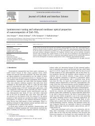
Figures 2.5 a & 2.5 b show the E/p variati<strong>on</strong> <strong>of</strong><br />
Gerdien c<strong>on</strong>densers used in ballo<strong>on</strong> and rocket experiments<br />
respectively. In the case <strong>of</strong> ballo<strong>on</strong>-borne sensors it can be<br />
seen that the E/p value is not exceeded for all sensors at 1 V<br />
and peak applied voltages, in the regi<strong>on</strong> <strong>of</strong> measurement.<br />
Therefore, in the case <strong>of</strong> ballo<strong>on</strong> experiments, the applied<br />
electric field is in the low field regime and so the mobility<br />
measurement in all experiments can be c<strong>on</strong>sidered to be<br />
independent <strong>of</strong> the electric field strength.<br />
In the case <strong>of</strong> rocket measurements, it can be seen<br />
-1<br />
that E/p value exceeds 250 Vm per mm <strong>of</strong> Hg, for an applied<br />
potential <strong>of</strong> 1 V at about 55 km; and for an applied voltage <strong>of</strong><br />
13V in the complete regi<strong>on</strong> <strong>of</strong> measurement. In all the<br />
experiments a linear sweep voltage was used as the driving<br />
potential. The sweeping voltage changes the E/p from low<br />
field to high field in the rocket experiments. Here the<br />
change from low field to high field is not important, but the<br />
important c<strong>on</strong>siderati<strong>on</strong> is whether the mobility is c<strong>on</strong>stant<br />
over the range <strong>of</strong> applied electric field. A linear<br />
current-voltage curve is indicative <strong>of</strong> c<strong>on</strong>stant mobility.<br />
Figure 2.6 shows the driving voltage and collector current<br />
60
....... 0.064 m sensor at 1 V<br />
-- 0.064 m sensor at 5 V<br />
a I ••• 0.064 m sensor at 35 V<br />
I I I I I 0.08 m sensor at 1 V<br />
••••• 0.08 m sensor at 5 V<br />
35 • • • •• 0.08 m sensor at 30V<br />
30<br />
25<br />
10<br />
5<br />
0.1 1 10<br />
E/p (V/m per mm<br />
1QO<br />
<strong>of</strong> Hg)<br />
FIGURE 2.5 a. Variati<strong>on</strong> <strong>of</strong> E/p with altitude in<br />
ballo<strong>on</strong>-borne c<strong>on</strong>densers, shown for<br />
the different peak voltages. It can be<br />
seen that the value <strong>of</strong> E/R does not<br />
exceed the limit <strong>of</strong> 250 Vm -1 per mm<br />
<strong>of</strong> Hg.<br />
61
80<br />
60<br />
20<br />
la 8 a a 8 0.042 m sensor at 1 V<br />
• • • •• 0.042 m sensor at 13 V<br />
ca ••• 1I 0.064 msensor at 1 V<br />
••••• 0.064 cm sensor at 13 V<br />
0.1 1 10 100<br />
E/p (V/m per<br />
1000 10000 100000<br />
mm <strong>of</strong> Hg)<br />
FIGURE 2.S.b Variati<strong>on</strong> <strong>of</strong> E/pwith altitude for the<br />
rocket sensors. The value exeeds<br />
250 Vm -1 per mm <strong>of</strong> Hg in the entire<br />
range measurement.<br />
62
"<br />
SWEEP<br />
SWEEP<br />
COLLECTOR<br />
CURRENT<br />
COLLECTOR<br />
CURRENT<br />
TIME<br />
'"'<br />
TIME<br />
..<br />
FIGURE 2.6 Reproduced data samples from rocket and ballo<strong>on</strong> experiments.<br />
The spikes seen in the amplifier outputs are due to change<br />
<strong>of</strong> slope <strong>of</strong> driving voltage. Ro cket data sample (left) is<br />
for unipolar measurement and ballo<strong>on</strong> data sample (right) is<br />
for bipolar measurement.<br />
'"
wave forms obtained from rocket and ballo<strong>on</strong> experiments. It<br />
can be seen that the current varies linearly with the driving<br />
voltage.<br />
2.3 1.3.Photo electr<strong>on</strong> producti<strong>on</strong>:<br />
A third factor to be c<strong>on</strong>sidered is the effect <strong>of</strong><br />
photo electr<strong>on</strong>s produced by solar ultra violet radiati<strong>on</strong>.<br />
Most <strong>of</strong> the radiati<strong>on</strong> that is energetic enough to generate<br />
photo electr<strong>on</strong>s are absorbed by the atmosphere above about<br />
60km altitude. Hence this is not a serious problem in<br />
ballo<strong>on</strong>-borne measurements which rarely go above 35 to 40km.<br />
However it becomes important in rocket experiments<br />
above 60km. If photo electr<strong>on</strong>s are produced from the<br />
electrode or the collector, they can add to the<br />
current when the driving electrode becomes negative.<br />
the ways to prevent this is to ensure that<br />
ultraviolet radiati<strong>on</strong> does not directly fall <strong>on</strong><br />
inside the sensor. Coating the electrodes with a<br />
having high i<strong>on</strong>isati<strong>on</strong> energy is also helpful.<br />
2.3.2. FLOW CONSIDERATIONS<br />
which go<br />
driving<br />
collector<br />
the<br />
One <strong>of</strong><br />
solar<br />
any part<br />
material<br />
In the classical theory <strong>of</strong> the Gerdien c<strong>on</strong>denser,<br />
the flow is assumed to be laminar, which means the Reynolds'<br />
number should be less than a critical. value. For two very<br />
l<strong>on</strong>g axial cylinders this value is 2000, but the exact figure<br />
for a given c<strong>on</strong>denser will have to be determined<br />
64
For a typical ballo<strong>on</strong>-borne instrument, the<br />
Reynolds· number varies c<strong>on</strong>siderably, from ·very high values<br />
near ground to very low values at float altitude. Paltridge<br />
calibrated his instrument for the range <strong>of</strong> Reynolds' numbers<br />
encountered by his instrument. He found that the flow rate<br />
remained more or less c<strong>on</strong>stant up to an altitude <strong>of</strong> about<br />
12km, but began to reduce thereafter reaching about 50% <strong>of</strong> the<br />
expected value at around 25km altitude. Even below 12km the<br />
flow rate was about 10% less than expected. He<br />
that c<strong>on</strong>ductivity measurements, which normally do<br />
also<br />
not<br />
showed<br />
depend<br />
<strong>on</strong> the flow rate, are affected if the velocity pr<strong>of</strong>ile across<br />
the c<strong>on</strong>denser alters from <strong>on</strong>e point to another. In his<br />
instrument he found the effect to be pr<strong>on</strong>ounced around 20km.<br />
Rosen and H<strong>of</strong>mann (1981) suspected that even with<br />
the correcti<strong>on</strong> for Reynolds· number the results did not give a<br />
true picture <strong>of</strong> the i<strong>on</strong> density and mobility pr<strong>of</strong>iles. They<br />
therefore used a pump to draw air through the c<strong>on</strong>denser. They<br />
found that unexpected fluctuati<strong>on</strong>s in the i<strong>on</strong> density pr<strong>of</strong>ile<br />
and a decrease in reduced mobility with altitude, seen when<br />
self aspirated c<strong>on</strong>densers are used, disappeared when the pump<br />
is used.<br />
Of the four ballo<strong>on</strong> experiments described here, two<br />
were c<strong>on</strong>ducted with self-aspirated sensors and the other two<br />
with force-aspirated <strong>on</strong>es. Figure 2.7 shows the variati<strong>on</strong><br />
with altitude <strong>of</strong> Reynolds· number for the ballo<strong>on</strong>-borne<br />
self-aspirated sensors, for maximum and minimum velocities<br />
66
encountered during flight. It is seen from the figure that<br />
for self-aspirated sensors, above about 9km, the Reynolds'<br />
number is less than 8000 for the highest ascent rate. In both<br />
self aspirated measurements the data could be obtained <strong>on</strong>ly<br />
above about 10km altitude.<br />
In the case <strong>of</strong> rocket-borne c<strong>on</strong>denser where the<br />
instrument is mounted <strong>on</strong> the rocket itself the problem is that<br />
<strong>of</strong> supers<strong>on</strong>ic flow. All sounding rockets have supers<strong>on</strong>ic<br />
velocities in the regi<strong>on</strong> <strong>of</strong> measurement, which is normally<br />
above 40 to 50km. At these velocities, a shock wave is formed<br />
at the fr<strong>on</strong>t end. Now the dynamics <strong>of</strong> the system is governed<br />
by the following expressi<strong>on</strong>:<br />
dU . ..2 dA<br />
(1-111) = -<br />
\T -"A<br />
where A is the area <strong>of</strong> inlet <strong>of</strong> the cylinder and M is the Mach<br />
number. For subs<strong>on</strong>ic flow, M < 1 and U decreases when A<br />
increases. But when the flow is supers<strong>on</strong>ic M > 1 and U<br />
decreases with decrease in A. If M approaches unity at any<br />
time during the flow, then a phenomen<strong>on</strong> called choking takes<br />
place. Thus the actual rate <strong>of</strong> flow depends to a great extent<br />
<strong>on</strong> the type <strong>of</strong> flow present. A theoretical computati<strong>on</strong> is<br />
possible when the inner electrode has a negligible boundary<br />
regi<strong>on</strong>. However this may not be true at all attitudes. Thus<br />
<strong>on</strong>ly an experimental calibrati<strong>on</strong> can be d<strong>on</strong>e <strong>on</strong> the<br />
instrument. C<strong>on</strong>ley (1974) carried out such a calibrati<strong>on</strong> <strong>of</strong><br />
68
very low atmospheric pressures. In such cases ·self aspirati<strong>on</strong><br />
is employed for generating air flow. In ballo<strong>on</strong>-borne<br />
measurements also self aspirati<strong>on</strong> may be employed. There are<br />
some problems encountered in ballo<strong>on</strong>-borne self aspirated<br />
measurements which are discussed in a later secti<strong>on</strong> dealing<br />
with the ballo<strong>on</strong> measurements. An air pump which can operate<br />
down to a few millibars <strong>of</strong> atmospheric pressure can be used<br />
for forced aspirated operati<strong>on</strong> <strong>of</strong> the Gerdien c<strong>on</strong>denser <strong>on</strong><br />
ballo<strong>on</strong>s. Forced aspirati<strong>on</strong> can significantly improve the<br />
quality <strong>of</strong> data, as observed by Rosen and H<strong>of</strong>mann (1981). The<br />
present work c<strong>on</strong>firms this. For ground based measurements any<br />
pump or fan may be used to generate air flow; the capacity <strong>of</strong><br />
the pump or fan being decided by the sensitivity <strong>of</strong> the<br />
current amplifier used for measuring collector current.<br />
2.4.2. DRIVING VOLTAGE:<br />
The I-V characteristic in Figure 2.2. shows the<br />
c<strong>on</strong>ductivity and i<strong>on</strong>-trap (saturati<strong>on</strong>) modes <strong>of</strong> operati<strong>on</strong> <strong>of</strong> a<br />
Gerdien c<strong>on</strong>denser. It can be seen from the figure that, by<br />
proper selecti<strong>on</strong> <strong>of</strong> driving voltage, the Gerdien c<strong>on</strong>denser may<br />
be operated in any<strong>on</strong>e <strong>of</strong> the modes. When the applied voltage<br />
is less than the saturati<strong>on</strong> voltage, the c<strong>on</strong>denser operates in<br />
the c<strong>on</strong>ductivity mode and the current-voltage relati<strong>on</strong>ship is<br />
governed by eqn.(15). It may be noted here that the collector<br />
current is then independent <strong>of</strong> the air flow rate. In other<br />
words, when the velocity <strong>of</strong> air flow increases, even though<br />
70
c<strong>on</strong>denser for each sample <strong>of</strong> measurement so that errors due to<br />
noise and amplifier drift are minimized. k triangular sweep<br />
varying from zero to a value greater than V is well suited<br />
SI<br />
for this purpose since the voltage varies linearly with time.<br />
However, a varying driving voltage generates a displacement<br />
current in the c<strong>on</strong>denser, which is proporti<strong>on</strong>al to the rate <strong>of</strong><br />
change <strong>of</strong> voltage. This gets added to the measured collector<br />
current, and hence has to be compensated for. When a<br />
triangular sweep is used as the driving voltage, the<br />
displacement current appears as a square wave at the output <strong>of</strong><br />
the current measurement circuit. This has to be eliminated<br />
from the output. When the square wave is eliminated by a<br />
suitable technique, the I-V characteristic is obtained, as<br />
shown in Figure 2.6. As menti<strong>on</strong>ed earlier, to calculate<br />
c<strong>on</strong>ductivity, the slope <strong>of</strong> the output is taken rather than a<br />
spot value so that error due to noise is minimized. By<br />
estimating v, the i<strong>on</strong> mobility and from the saturati<strong>on</strong><br />
s<br />
current the i<strong>on</strong> density are also calculated.<br />
2.5. THE SENSOR; PRACTICAL CONSIDERATIONS:<br />
2.5. 1. ASSEMBL Y:<br />
Secti<strong>on</strong>al view <strong>of</strong> a typical Gerdien c<strong>on</strong>denser is<br />
shown in Figure 2.8. The outermost cylinder is the shield.<br />
The driving electrode slips into this shield and is insulated<br />
from it by hylam rings. Both ends <strong>of</strong> the shield are threaded<br />
and two threaded, bevelled end rings fit at the ends. These<br />
72
end rings are tightened to secure the<br />
positi<strong>on</strong>. Two hylam rings at both<br />
electrode insulate it from the end<br />
driving<br />
ends <strong>of</strong><br />
rings.<br />
electrode in<br />
the driving<br />
<strong>Electric</strong>al<br />
c<strong>on</strong>necti<strong>on</strong> to the driving electrode is accomplished through a<br />
10 mm port <strong>on</strong> the shield. The assembly is supported by three<br />
legs and the legs are fastened to the base. A tube extending<br />
from the base supports the collector. The stepped lower<br />
porti<strong>on</strong> <strong>of</strong> the collector slips through the tube and is<br />
insulated from it by a P.T.F.E.(Tefl<strong>on</strong>) sheath <strong>of</strong> 2 mm<br />
thickness. The lower end <strong>of</strong> the collector rod is threaded and<br />
it is fastened to the base with a nut and a P.T.F.E. washer.<br />
The base is hollow and electrical c<strong>on</strong>necti<strong>on</strong> to the collector<br />
is made at the lower end <strong>of</strong> the collector rod. The end rings,<br />
shield, legs and the base are electrically grounded through<br />
the rocket body or the g<strong>on</strong>dola which ever is the case. The<br />
base and the tip <strong>of</strong> the collector are suitably shaped to<br />
facilitate free air flow.<br />
2.5.2. MATERIAL:<br />
The shield, the end rings and the base are made <strong>of</strong><br />
Aluminium and the legs are made <strong>of</strong> mild steel. The electrodes<br />
are made <strong>of</strong> brass and electroplated with Nickel. Aluminium is<br />
used because it is light in weight, is easy for fabricati<strong>on</strong><br />
and it does not require a protective coating for normal use.<br />
Aluminium always has an oxide coating over the surface.<br />
Because <strong>of</strong> the oxide coating Aluminium cannot be used for the<br />
74
electrodes since they cause a level shift in the output due to<br />
c<strong>on</strong>tact resistance between air and the electrode (Widdel et.<br />
al. 1976). Brass electrodes, electroplated with Nickel<br />
provides a polished corrosi<strong>on</strong> free surface. Legs are made <strong>of</strong><br />
mild steel so that they can withstand the severe shock and<br />
vibrati<strong>on</strong> that the pay load will be subjected to during launch<br />
and powered flight.<br />
Two types <strong>of</strong> material have been used for insulati<strong>on</strong><br />
in the sensor <strong>of</strong> which hylam is a relatively poor quality<br />
insulator. Insulati<strong>on</strong> <strong>of</strong> this quality is sufficient for the<br />
driving electrode since it is usually driven by a low<br />
impedance source and so leakages <strong>of</strong> the order <strong>of</strong> even a<br />
fracti<strong>on</strong> <strong>of</strong> a milliampere can be tolerated. Virgin P.T.F.E.<br />
is a high quality insulator and it is essential that the<br />
collector is insulated by such a material, since leakages <strong>of</strong><br />
-14<br />
the order <strong>of</strong> even 10 ampere cannot be tolerated. P.T.F.E.<br />
also has the advantage that its surface can be polished and<br />
cleaned to minimize surface leakage. There is <strong>on</strong>e<br />
disadvantage with P.T.F.E. which becomes important in a<br />
vibrati<strong>on</strong> envir<strong>on</strong>ment. In a vibrati<strong>on</strong> envir<strong>on</strong>ment, P.T.F.E.<br />
causes the producti<strong>on</strong> <strong>of</strong> what is known as triboelectric noise<br />
(Harris and Crede, 1976). The amplitude <strong>of</strong> the noise can<br />
sometimes be as high as the signal itself. In the Gerdien<br />
c<strong>on</strong>densers used in the experiments described here, collector<br />
rods are insulated from their supports by means <strong>of</strong><br />
P.T.F.E.tubes(sheaths). Producti<strong>on</strong> <strong>of</strong> noise in these Gerdien<br />
75
CHAPTER-3<br />
u P PER ATMOSPHERIC MEASUREMENTS<br />
This chapter deals with upper atmospheric<br />
measurements. The measurements were c<strong>on</strong>ducted using rockets<br />
flown from Thumba Equatorial Rocket Launching Stati<strong>on</strong> (TERLS),<br />
Thiruvananthapuram, India (Geog. Lat:<br />
o<br />
8.54, L<strong>on</strong>g:<br />
o<br />
76.86 ).<br />
The experimental details and the results obtained from these<br />
rocket experiments are discussed. The chapter is divided into<br />
two secti<strong>on</strong>s. The first secti<strong>on</strong> deals with the experimental<br />
details and the sec<strong>on</strong>d <strong>on</strong>e with the results.<br />
3.1. THE PAYLOAD:<br />
Five rocket experiments were d<strong>on</strong>e using the Gerdien<br />
c<strong>on</strong>denser technique. The first two payloads were instrumented<br />
to measure positive i<strong>on</strong> densities and their mobilities. The<br />
later three payloads measured both positive and negative i<strong>on</strong><br />
densities and their mobilities. In these payloads, in-flight<br />
calibrati<strong>on</strong> also was incorporated. Figure.3.1 shows the block<br />
diagram <strong>of</strong> the payload. The part <strong>of</strong> the diagram shown in<br />
dashed lines indicate the modificati<strong>on</strong>s incorporated in the<br />
payload from third flight <strong>on</strong>wards.<br />
78
The blocks are discussed in detail here.<br />
3.1.1.THE GERDIEN CONDENSER SENSOR:<br />
Two major c<strong>on</strong>straints in designing the rocket sensor<br />
are the limitati<strong>on</strong> in dimensi<strong>on</strong> enforced by the type <strong>of</strong> rocket<br />
and the total payload weight that can be flown. Another<br />
design c<strong>on</strong>straint is the large shock during take <strong>of</strong>f and the<br />
severe vibrati<strong>on</strong> during powered flight <strong>of</strong> the rocket. The<br />
sensor has to be designed and fabricated in such a way that it<br />
withstands the shock and vibrati<strong>on</strong> <strong>of</strong> the rocket <strong>on</strong> which it<br />
will be flown. The first two experiments were flown <strong>on</strong> M100-B<br />
rockets and the later <strong>on</strong>es <strong>on</strong> Rohini-300. The dimensi<strong>on</strong>s <strong>of</strong><br />
the sensors flown in these two types were slightly different<br />
to suit each <strong>of</strong> these rockets. The details <strong>of</strong> the dimensi<strong>on</strong>s<br />
are given later. Here, we describe the general design <strong>of</strong> a<br />
typical rocket sensor.<br />
Figure 3.2. shows the sensor at various stages <strong>of</strong><br />
fabricati<strong>on</strong>. The sensor c<strong>on</strong>sists <strong>of</strong> a<br />
shield, end rings, legs to support<br />
driving electrode, a<br />
the driving electrode<br />
assembly, a base, a collector, and a set <strong>of</strong> insulators.<br />
The driving electrode is a brass tube electroplated<br />
with nickel. This driving electrode is held inside the shield<br />
with the help <strong>of</strong> insulating hylam rings such that the shield<br />
protrudes at both ends. The shield is made <strong>of</strong> an Aluminium<br />
tube slightly larger in diameter and l<strong>on</strong>ger in length than the<br />
driving electrode. Both ends <strong>of</strong> the shield are threaded and<br />
two threaded, bevelled rings fit at the ends. These end rings<br />
80
functi<strong>on</strong> as guard rings. The end rings and the insulating<br />
hylam rings at the ends <strong>of</strong> the driving elec'trode are made such<br />
that when the end rings are tightened the driving electrode is<br />
secured in positi<strong>on</strong>. Also the inner diameter <strong>of</strong> end rings and<br />
the hylam rings at the ends are such that the air flow through<br />
the sensor is smooth. <strong>Electric</strong>al c<strong>on</strong>necti<strong>on</strong> to the driving<br />
electrode is accomplished through a 10 mm port <strong>on</strong> the shield.<br />
The driving electrode and shield assembly<br />
are supported by three legs made <strong>of</strong> mild steel. The legs are<br />
fastened to the shield using screws and nuts<br />
that the insulati<strong>on</strong> between the shield<br />
electrode is not affected. The lower end <strong>of</strong><br />
in such a way<br />
and the driving<br />
the legs slip<br />
into three slots in the base and are fastened using screws and<br />
nuts. Also, the legs are made in such a way that <strong>on</strong><br />
completi<strong>on</strong> <strong>of</strong> assembly <strong>of</strong> the sensor, the ends <strong>of</strong> both driving<br />
electrode and collector are exactly at the same level.<br />
A tube extending from the base supports the<br />
collector. The collector rod is made <strong>of</strong><br />
electroplated with nickel. The collector rod<br />
upper porti<strong>on</strong> and a stepped thin lower porti<strong>on</strong>.<br />
thick porti<strong>on</strong> is fabricated in two steps. First<br />
brass<br />
has a<br />
and<br />
thick<br />
The upper<br />
the rod is<br />
machined and then some material is removed from inside by<br />
drilling. Then the tip is made and brazed <strong>on</strong>to the collector<br />
rod. This material removal not <strong>on</strong>ly helps in reducing weight<br />
but also minimizes the chances <strong>of</strong> vibrati<strong>on</strong> failure. The<br />
stepped lower porti<strong>on</strong> <strong>of</strong> the collector slips through a tube<br />
82
telemetered. The telemetry input voltage range is from 0 to<br />
5V and so the driving voltage wave form is attenuated<br />
range <strong>of</strong> about 0 to 4 V (the exact value changes from<br />
to flight) by the sweep m<strong>on</strong>itor amplifier and fed to<br />
m<strong>on</strong>itoring channel <strong>of</strong> telemetry.<br />
to a<br />
flight<br />
sweep<br />
The frequency <strong>of</strong> the sweep is set by the the<br />
resistance and capacitance <strong>of</strong> the integrator. Depending <strong>on</strong><br />
the number <strong>of</strong> samples required for every kilometer <strong>of</strong> altitude<br />
the frequency <strong>of</strong> sweep is decided. For example in the first<br />
flight a sweep <strong>of</strong> about 5 Hz was used. With a maximum rocket<br />
velocity <strong>of</strong> 1 km/s the sweep <strong>of</strong> 2 Hz yields four data points<br />
for every kilometer <strong>of</strong> altitude.<br />
The sweep applied to the sensor<br />
wave at the output <strong>of</strong> the electrometer<br />
produces a<br />
amplifier<br />
square<br />
due to<br />
displacement current. This is compensated by adding a similar<br />
inverted square wave to the current measurement system. In<br />
the first two experiments the sweep was fed to an R-C circuit<br />
to generate the square wave required for compensati<strong>on</strong>. In the<br />
later experiments a square wave available in the sweep<br />
generator was used instead. This method <strong>of</strong> compensati<strong>on</strong> was<br />
found to be more stable.<br />
3.1.3.THE CURRENT MEASUREMENT SYSTEM:<br />
Figure.3.4 a & b shows the block diagram and circuit<br />
diagram <strong>of</strong> the system used for measuring collector current in<br />
the first two experiments. The heart <strong>of</strong> the system is an<br />
89
volts for zero collector current. This was needed because the<br />
rocket telemetry would accept input voltages' from 0 to 5 V<br />
<strong>on</strong>ly.<br />
With this telemetry input range<br />
sensitivity and range <strong>of</strong> measurement for each<br />
the overall<br />
experiment is<br />
determined by the dimensi<strong>on</strong>s <strong>of</strong> the sensor, speed <strong>of</strong> air flow,<br />
the electrometer amplifier sensitivity and gain <strong>of</strong> amplifiers.<br />
Therefore, taking all these factors into c<strong>on</strong>siderati<strong>on</strong> the<br />
gain <strong>of</strong> amplifiers for each experiment is decided.<br />
The payloads <strong>of</strong> third, fourth and fifth experiments<br />
c<strong>on</strong>tained a system for sweep zero check and in-flight<br />
calibrati<strong>on</strong>. Sweep zero check is d<strong>on</strong>e by grounding the<br />
driving electrode after disc<strong>on</strong>necting the sweep for a few<br />
hundred millisec<strong>on</strong>ds. Sweep zero check helps not <strong>on</strong>ly in<br />
estimating c<strong>on</strong>tact potentials if any but also serves in<br />
estimating the reference value <strong>of</strong> all outputs <strong>of</strong> the current<br />
measurement system when the collector current is zero.<br />
Followed by the sweep zero check, the amplifiers are<br />
disc<strong>on</strong>nected from the electrometer amplifier and a calibrati<strong>on</strong><br />
signal derived from a reference source is fed to the<br />
amplifiers. The calibrati<strong>on</strong> period also is <strong>of</strong> the order <strong>of</strong> a<br />
few hundred millisec<strong>on</strong>ds. The whole process is repeated at an<br />
interval <strong>of</strong> approximately 30 sec<strong>on</strong>ds. The clock output <strong>of</strong> the<br />
sweep generator is used to c<strong>on</strong>trol the process as menti<strong>on</strong>ed<br />
earlier so that the calibrati<strong>on</strong> and sweep zero check were d<strong>on</strong>e<br />
synchr<strong>on</strong>ous with the sweep.<br />
92
3.1.4.CALIBRATION AND TESTING:<br />
The current measurement system was calibrated with a<br />
Keithley picoampere current source (calibrated against N.B.S.,<br />
U.S.A). The calibrati<strong>on</strong> was d<strong>on</strong>e al<strong>on</strong>g with the cable<br />
c<strong>on</strong>necting the sensor to the electrometer amplifier. Further<br />
the attenuati<strong>on</strong> factor and phase relati<strong>on</strong>ship <strong>of</strong> the output <strong>of</strong><br />
the sweep m<strong>on</strong>itor amplifier to the sweep applied to the sensor<br />
is noted.<br />
After fabricati<strong>on</strong>, the payload<br />
tested at various temperatures from<br />
satisfactory performance. The payload<br />
with other systems in the rocket and<br />
was<br />
was<br />
checked<br />
functi<strong>on</strong>ing. Vibrati<strong>on</strong>, shock and accelerati<strong>on</strong><br />
then c<strong>on</strong>ducted <strong>on</strong> the integrated payload.<br />
calibrated and<br />
to 70°C for<br />
then integrated<br />
for proper<br />
checks were<br />
By the time the third flight was c<strong>on</strong>ducted a set <strong>of</strong><br />
mandatory tests known as GATE tests to evaluate the flight<br />
worthiness <strong>of</strong> scientific payloads had come into operati<strong>on</strong>.<br />
The GATE test is meant to weed out weaklings and serves the<br />
purpose <strong>of</strong> early detecti<strong>on</strong> <strong>of</strong> inherent weakness.<br />
GATE test report is given in TABLE 3.2.<br />
A typical<br />
93
Type <strong>of</strong><br />
test<br />
I.70°C,<br />
8 hr unpowered,<br />
1hr<br />
powered.<br />
II.10°C,<br />
1 hr.unpowered,<br />
10 mt<br />
powered<br />
Parameter<br />
measured.<br />
a.Calibrati<strong>on</strong>:<br />
1. 2 gain cal.<br />
output<br />
2 10 gain cal.<br />
output<br />
b.Sweep zerooutputs<br />
TABLE 3.2.<br />
GATE TEST REPORT<br />
THIRD FLIGHT<br />
Expected<br />
value.<br />
1. 8 V,<br />
3.6 V.<br />
0.9 V,<br />
1. 8 V.<br />
1.E M 50 mV<br />
Amplifier<br />
2.2 gain -50 mV<br />
amplifier<br />
3.10 gain -250 mV<br />
amplifier<br />
4.Negative output 250 mV<br />
amplifier<br />
5.Sweep 2 V<br />
m<strong>on</strong>itor<br />
c.Sweep<br />
1.Sweep<br />
voltage<br />
2.Sweep<br />
period<br />
3.Sweep<br />
m<strong>on</strong>itor<br />
output<br />
a.Calibrati<strong>on</strong>:<br />
1. 2 gain cal.<br />
output<br />
2 10 gain cal.<br />
output<br />
Obtained<br />
value<br />
1. 9 V,<br />
3.7 V.<br />
1.1 V,<br />
2.0 V.<br />
50 mV<br />
-40 mV<br />
-210 mV<br />
200 mV<br />
2 V<br />
+13V,-12V +13V,-12V<br />
480 m s 480 ms<br />
o to 3.8V 0 to 3.8V<br />
1.8 V, 1.8 V,<br />
3.6 V. 3.6 V.<br />
0.9 V, 0.9 V,<br />
1.8 V. 1.8 V.<br />
Remarks<br />
Acceptable. <br />
Acceptable. <br />
Acceptable. <br />
Acceptable.<br />
94
Type <strong>of</strong><br />
test<br />
III.<br />
96 hr<br />
Burn-in,<br />
room<br />
temp. ,<br />
powered<br />
Parameter<br />
measured.<br />
b.Sweep zerooutputs<br />
1. E H<br />
Amplifier<br />
2.2 gain<br />
amplifier<br />
3.10 gain<br />
amplifier<br />
4.Negative output<br />
amplifier<br />
5.Sweep<br />
m<strong>on</strong>itor<br />
c.Sweep<br />
1.Sweep<br />
voltage<br />
2.Sweep<br />
period<br />
3.Sweep<br />
m<strong>on</strong>itor<br />
output<br />
a.Calibrati<strong>on</strong>:<br />
1. 2 gain cal.<br />
output<br />
2 10 gain cal.<br />
output<br />
b.Sweep zerooutputs<br />
1. E H<br />
Amplifier<br />
2.2 gain<br />
amplifier<br />
3.10 gain<br />
amplifier<br />
4.Negative output<br />
amplifier<br />
5.Sweep<br />
m<strong>on</strong>itor<br />
Expected<br />
value.<br />
15 mV<br />
20 mV<br />
100 mV<br />
-100 mV<br />
2 V<br />
Obtained<br />
value<br />
15 mV<br />
20 mY'<br />
90 mV<br />
-110 mV<br />
2 V<br />
+13V,-12V +13V,-12V<br />
480 m s 480 ms<br />
o to 3.8V 0 to 3.8V<br />
1. 8 V,<br />
3.6 V.<br />
0.9 V,<br />
1. 8 V.<br />
35 mV<br />
-20 mV<br />
-100 mY<br />
100 mV<br />
2 V<br />
1. 8 V,<br />
3.6 V.<br />
0.9 V,<br />
1. 8 V.<br />
40 mV<br />
-35 mY<br />
-135 mV<br />
135 mV<br />
2 V<br />
Remarks<br />
Acceptable. <br />
Acceptable. <br />
Acceptable. <br />
Acceptable.<br />
95
Type <strong>of</strong> Parameter Expected Obtained Remarks<br />
test measured. value. value<br />
V. a.Calibrati<strong>on</strong>:<br />
Vibrati<strong>on</strong>, 1. 2 gain cal<br />
3 axes, output<br />
X,Y&Z. 2 10 gain cal<br />
Sine output<br />
20 Hz to<br />
2 kHz. b.Sweep zero-<br />
Random outputs<br />
20 Hz to<br />
LE M<br />
2 kHz.<br />
Amplifier<br />
2.2 gain<br />
amplifier<br />
3.10 gain<br />
amplifier<br />
4.Negative output<br />
amplifier<br />
1.8 V,<br />
3.6 V.<br />
0.9 V,<br />
1.8 V.<br />
25 mV<br />
2 mV<br />
5 mV<br />
0<br />
1.8 V,<br />
3.6 V.<br />
0.9 V,<br />
1.8 V.<br />
25 mV<br />
2 mV<br />
5 mV<br />
0<br />
Acceptable.Accept-<br />
able.<br />
5.Sweep<br />
m<strong>on</strong>itor<br />
2 V 2 V<br />
c.Sweep<br />
1.Sweep +13V,-12V +13V,-12V<br />
voltage<br />
2.Sweep 480 m s 480 ms Acceptperiod<br />
able.<br />
3.Sweep 0 to 3.8V 0 to 3.8V<br />
m<strong>on</strong>itor<br />
output<br />
VI. a.Calibrati<strong>on</strong>:<br />
Accelera- 1. 2 gain cal 1.8 V, 1.8 V,<br />
ti<strong>on</strong>. output 3.6 V. 3.6 V. Accept-<br />
3515, 2 10 gain cal 0.9 V, 0.9 V, able.<br />
1mt. output 1.8 V. 1.8 V.<br />
b.Sweep zerooutputs<br />
LE M 25 mV 25 mV<br />
Amplifier<br />
2.2 gain 2 mV 2 mV<br />
amplifier<br />
3.10 gain 5 mV 5 mV Acceptamplifier<br />
able.<br />
97
Type <strong>of</strong> Parameter Expected Obtained<br />
test measured. value. value<br />
4.Negative output 0 0<br />
amplifier<br />
5.Sweep 2 V 2 V<br />
m<strong>on</strong>itor<br />
c.Sweep<br />
1.Sweep +13V,-12V +13V,-12V<br />
voltage<br />
2.Sweep 480 m s 480 ms<br />
period<br />
3.Sweep 0 to 3.8V 0 to 3.8V<br />
m<strong>on</strong>itor<br />
output<br />
Equipment used :<br />
1. Tektr<strong>on</strong>ics oscilloscope.<br />
2. Keithley Picoampere source.<br />
Facility :<br />
Vibrati<strong>on</strong> and accelerati<strong>on</strong> test - V.S.S.C.<br />
All other tests - C E S S.<br />
3.1.5 PAYLOAD LAYOUT:<br />
Remarks<br />
Acceptable.<br />
The first two flights were c<strong>on</strong>ducted using M100-B<br />
rockets, and the remaining using Rohini-300s(RH-300). The<br />
M-100B has a steeple at the tip which can be split and<br />
ejected. The Gerdien c<strong>on</strong>denser was mounted inside this<br />
steeple. In RH-300 rockets the sensor was mounted <strong>on</strong> the<br />
98
top-most deck in the nose c<strong>on</strong>e, and the nose c<strong>on</strong>e was ejected.<br />
Sketches <strong>of</strong> sensor mounting in these two types <strong>of</strong> rockets is<br />
shown in Figure 3.5.<br />
Figure 3.5. also shows the electr<strong>on</strong>ics box mounted<br />
just below the sensor in the case <strong>of</strong> RH-300 rocket. In the<br />
case <strong>of</strong> M-100B the electr<strong>on</strong>ics was mounted <strong>on</strong> the topmost deck<br />
namely DECK 1. In both the cases the electr<strong>on</strong>ics box had two<br />
c<strong>on</strong>nectors, <strong>on</strong>e P.T.F.E insulated co-axial c<strong>on</strong>nector and<br />
another rack and panel c<strong>on</strong>nector. The co-axial c<strong>on</strong>nector was<br />
used for c<strong>on</strong>necting the electrometer amplifier to the<br />
collector. Power inputs to and telemetry outputs from the<br />
electr<strong>on</strong>ics were taken through the rack and panel c<strong>on</strong>nector.<br />
An RG-178 P.T.F.E insulated cable was used to c<strong>on</strong>nect the<br />
collector to the electrometer amplifier. Amplifier end<br />
c<strong>on</strong>necti<strong>on</strong> <strong>of</strong> the cable was accomplished through the co-axial<br />
c<strong>on</strong>nector and at the sensor end the inner c<strong>on</strong>ductor was<br />
soldered to a terminal at the lower end <strong>of</strong> the collector. The<br />
cable was anchored every few centimeters to reduce vibrati<strong>on</strong>.<br />
The shield <strong>of</strong> the cable was grounded <strong>on</strong>ly at the box end to<br />
avoid ground loop problems.<br />
in table.3.3.<br />
Experimental details <strong>of</strong> all rocket flights are given<br />
99
Flight Type <strong>of</strong> Launch<br />
No rocket date<br />
Table 3......J.<br />
Details Q[ rocket experiments<br />
Launch Solar 10.7 cm<br />
time zenith flux<br />
I S T angle (F 10 .?)<br />
1 11-100B 29.11.1982 1051 34.So 1Sl<br />
2 11-100B 9. 2.1984 1609 59.4° 140<br />
3 RH-300 3.10.198S 0935 43.4° 72<br />
4 RH-300 12. 4.1988 0910 ---- ---<br />
5 RH-300 S .11.1988 0840 59° 1Sl<br />
In all the flights the sensor was exposed at an<br />
altitude <strong>of</strong> about 50 to 55 km. Good data were obtained during<br />
the ascent. Air flow during descent is complicated and<br />
n<strong>on</strong>uniform and so descent data was not taken for analysis.<br />
Data from the fourth flight was found to be not good<br />
and hence was not analysed.<br />
3. 2. D1 SCUSSI ON:<br />
3.2.1.POSITIVE ION DENSITIES:<br />
The positive i<strong>on</strong> densities obtained from the four<br />
flights are shown in Figure 3.S. All these measurements show<br />
that the i<strong>on</strong> density decreases initially and reaches a minimum<br />
around SO-65 km. It then increases with altitude in the<br />
mesosphere. The producti<strong>on</strong> mechanisms <strong>of</strong> positive i<strong>on</strong>s in the<br />
atmosphere indicate that while galactic cosmic rays c<strong>on</strong>stitute<br />
101
energy <strong>of</strong> the incident phot<strong>on</strong>.<br />
For low levels <strong>of</strong> solar activity; this source <strong>of</strong><br />
i<strong>on</strong>s is small compared to that produced by the Lyman-a line.<br />
On the other hand its c<strong>on</strong>tributi<strong>on</strong> becomes more important<br />
during disturbed c<strong>on</strong>diti<strong>on</strong>s. For example, solar irradiance <strong>of</strong><br />
X-rays from O.lnm to 0.8 nm intensifies by about 1000 times<br />
for active c<strong>on</strong>diti<strong>on</strong>s, and may increase by an additi<strong>on</strong>al<br />
factor <strong>of</strong> 100 during solar flares.<br />
The absorpti<strong>on</strong> <strong>of</strong> solar radiati<strong>on</strong> in the spectral<br />
regi<strong>on</strong> from 102.7 nm to 111.8 nm represents an additi<strong>on</strong>al<br />
source <strong>of</strong> D-regi<strong>on</strong> i<strong>on</strong>izati<strong>on</strong> as suggested by Hunten and<br />
HcElroy (1968), but the rate <strong>of</strong> i<strong>on</strong> formati<strong>on</strong> is much smaller<br />
than that by Lyman-a .<br />
Hence for typical c<strong>on</strong>diti<strong>on</strong>s, most <strong>of</strong> the i<strong>on</strong>izati<strong>on</strong><br />
in the D-regi<strong>on</strong> is due to the effect <strong>of</strong> the solar Lyman-a <strong>on</strong><br />
Nitric oxide (Nicolet,1945). The i<strong>on</strong>izati<strong>on</strong> potential <strong>of</strong> NO<br />
molecule is 9.25 eV, which corresp<strong>on</strong>ds to a wave length <strong>of</strong> 134<br />
nm. In the spectral regi<strong>on</strong> <strong>of</strong> the Lyman-a line an atmospheric<br />
window exists due to the low absorpti<strong>on</strong> cross secti<strong>on</strong> <strong>of</strong> 02 in<br />
this interval, and thus the i<strong>on</strong>izing radiati<strong>on</strong> can penetrate<br />
relatively far into the mesosphere.<br />
Hence, above about 60-65 km the main source <strong>of</strong><br />
i<strong>on</strong>isati<strong>on</strong> is solar radiati<strong>on</strong>, and i<strong>on</strong>isati<strong>on</strong> in this regi<strong>on</strong><br />
therefore will be dependent <strong>on</strong> solar zenith angle and solar<br />
activity. The i<strong>on</strong>isati<strong>on</strong> is directly related to the level <strong>of</strong><br />
solar activity but inversely to the solar zenith angle.<br />
104
<strong>of</strong> higher solar activity has measured lower densities than the<br />
sec<strong>on</strong>d, as seen from the pr<strong>of</strong>iles shown in Figure 3.7.b. One<br />
reas<strong>on</strong> for this could be the difference in nitric oxide<br />
c<strong>on</strong>centrati<strong>on</strong>. Seas<strong>on</strong>al variati<strong>on</strong>s <strong>of</strong> NO up to two or three<br />
orders <strong>of</strong> magnitude have been reported (Kopp and<br />
Herrmann,1984). The two flights have been c<strong>on</strong>ducted in the<br />
m<strong>on</strong>ths <strong>of</strong> November and February, though four years apart.<br />
Hence the seas<strong>on</strong>al effects may not be significantly felt in<br />
the measurements. But this effect cannot be completely ruled<br />
out. The sec<strong>on</strong>d possibility is an asymmetry about no<strong>on</strong> in<br />
i<strong>on</strong>isati<strong>on</strong>. A<br />
flight was the<br />
careful examinati<strong>on</strong><br />
<strong>on</strong>ly <strong>on</strong>e c<strong>on</strong>ducted<br />
possible asymmetry in i<strong>on</strong>isati<strong>on</strong><br />
shows<br />
in the<br />
between<br />
that the sec<strong>on</strong>d<br />
afterno<strong>on</strong>. A<br />
foreno<strong>on</strong> and<br />
afterno<strong>on</strong> can be a reas<strong>on</strong> for the i<strong>on</strong> densities in the sec<strong>on</strong>d<br />
flight to be higher. Such an asymmetry in i<strong>on</strong> c<strong>on</strong>centrati<strong>on</strong><br />
with respect to no<strong>on</strong> has not been reported for comparis<strong>on</strong> with<br />
these measurements.<br />
However, asymmetries in electr<strong>on</strong> c<strong>on</strong>centrati<strong>on</strong> have<br />
been reported by Aikin et al(1972), Gregory and Mans<strong>on</strong> (1969)<br />
and others. To be more specific Haug et al (1970) from<br />
partial reflecti<strong>on</strong> measurements at Crete (35 0 N) in May 1966<br />
found electr<strong>on</strong> density values to be maximised 2 hours after<br />
local no<strong>on</strong> at 80 km. But this was not apparent in the<br />
measurements made from the same stati<strong>on</strong> in the autumn <strong>of</strong> 1964<br />
and 1965. Asymmetries were also observed in the partial<br />
reflecti<strong>on</strong> data at Urbana, Illinois, (40 o N), with a tendency<br />
107
for higher electr<strong>on</strong> densities in the morning (Weiland et<br />
al.,1983). Chakrabarthy et al (1983) try to explain this as<br />
due to a possible asymmetry in temperature. Temperature<br />
indirectly affects the electr<strong>on</strong> loss coefficient in a way that<br />
it decreases with increase in temperature. A decrease in loss<br />
coefficient leads to a higher electr<strong>on</strong> c<strong>on</strong>centrati<strong>on</strong>. Thus,<br />
an increase in temperature can cause an increase in electr<strong>on</strong><br />
c<strong>on</strong>centrati<strong>on</strong> and so an asymmetry in temperature about<br />
no<strong>on</strong> would cause an asymmetry in electr<strong>on</strong> density.<br />
possibilities <strong>of</strong> such an asymmetry in temperature<br />
asymmetry in i<strong>on</strong> density also needs to be<br />
local<br />
The<br />
causing an<br />
studied.<br />
Simultaneous measurements <strong>of</strong> i<strong>on</strong> and electr<strong>on</strong> densities at the<br />
same zenith angles at foreno<strong>on</strong> and after no<strong>on</strong> <strong>on</strong> the same day<br />
will help us to understand this. A perfect understanding may<br />
still elude us, as accurate measurements <strong>of</strong> temperature in the<br />
mesopause face certain problems.<br />
Thus the i<strong>on</strong> density pr<strong>of</strong>iles obtained from these<br />
rocket flights show the effect <strong>of</strong> solar activity and zenith<br />
angle <strong>on</strong> positive i<strong>on</strong> density. Also the minimum in i<strong>on</strong><br />
density at 60-65 km brought about by the combined effect <strong>of</strong><br />
solar Lyman-a and galactic cosmic rays is seen clearly. A<br />
possible asymmetry in i<strong>on</strong> density with respect to no<strong>on</strong> is also<br />
suggested.<br />
108
+<br />
H (H 0) cannot be made from Gerdien c<strong>on</strong>denser<br />
Z n<br />
measurements<br />
because mobility is not a sensitive functi<strong>on</strong> <strong>of</strong> i<strong>on</strong> mass.<br />
However, the values reported here are very close to those<br />
obtained using Gerdien c<strong>on</strong>densers by C<strong>on</strong>ley(1974), Rose and<br />
Widdel (1972) and others.<br />
Measurements <strong>of</strong> mobilities <strong>of</strong> a large variety <strong>of</strong><br />
molecular i<strong>on</strong>s, both positive and negative, in dry nitrogen<br />
have been made by Kilpatric (Meyerotte et. al.1980).<br />
Similarly Mitchell and Rider (Meyerotte et. al.1980) made<br />
reduced mobility measurements <strong>of</strong> a variety <strong>of</strong> positive atomic<br />
i<strong>on</strong>s in dry nitrogen. Figure 3.9. shows the mass dispersi<strong>on</strong><br />
curves from these two measurements. The curve is reproduced<br />
from Meyerotte et al (1980). Measurements <strong>of</strong> mobilities <strong>of</strong><br />
hydr<strong>on</strong>ium i<strong>on</strong>s <strong>of</strong> masses 19,37 & 55 amu in nitrogen by Dotan<br />
(Meyerotte et. al.1980) and that <strong>of</strong> Huertas et al. (Meyerotte<br />
et. al.1980) <strong>of</strong> hydr<strong>on</strong>ium i<strong>on</strong>s <strong>of</strong> masses 73,91 & 109 amu also<br />
follow these curves closely.<br />
An attempt has been made to identify the mass <strong>of</strong> the<br />
observed i<strong>on</strong>s from this mass dispersi<strong>on</strong> curve. Figure 3.9<br />
also shows the range <strong>of</strong> reduced mobility <strong>of</strong> positive and<br />
negative i<strong>on</strong>s obtained from the measurements described here.<br />
By this method <strong>of</strong> evaluati<strong>on</strong> it has been found that the<br />
measured mobilities corresp<strong>on</strong>d more or less to that <strong>of</strong> water<br />
cluster i<strong>on</strong>s with n=2 or 3.<br />
111
10"<br />
S' 10 J<br />
E<br />
o<br />
10 2<br />
10<br />
o<br />
3.2.3.NEGATIVE ION DENSITIES:<br />
The pr<strong>of</strong>iles <strong>of</strong> negative i<strong>on</strong> densities obtained in<br />
the third and the fifth flights are shown in Figure.3.10. The<br />
density <strong>of</strong> negative i<strong>on</strong>s is comparable to that <strong>of</strong> positive<br />
i<strong>on</strong>s up to the altitude where positive i<strong>on</strong> density reaches the<br />
minimum. The negative i<strong>on</strong> density c<strong>on</strong>tinues to decrease and<br />
reaches a minimum at a slightly higher altitude than the<br />
positive i<strong>on</strong>s. It then increases gradually with altitude and<br />
reaches a broad maximum around 85 km. The i<strong>on</strong> density falls<br />
rapidly bey<strong>on</strong>d and disappears around 90 km.<br />
The first studies in i<strong>on</strong>osphere using radio wave<br />
techniques dem<strong>on</strong>strated that electr<strong>on</strong>s are nearly absent below<br />
65 or 70 km during day and 75 or 80 km during night. After<br />
the first measurement <strong>of</strong> Johns<strong>on</strong> et al (1958) there have been<br />
<strong>on</strong>ly a very few measurements <strong>of</strong> negative i<strong>on</strong>s. Narcisi et<br />
al(1971) and Arnold et al (1971) observed the regi<strong>on</strong> at night.<br />
The presence <strong>of</strong> a transiti<strong>on</strong> z<strong>on</strong>e above which the<br />
c<strong>on</strong>centrati<strong>on</strong> <strong>of</strong> negative i<strong>on</strong> decrease was established by<br />
observati<strong>on</strong> but the altitude <strong>of</strong> this layer seemed to vary<br />
c<strong>on</strong>siderably with time (Arnold and Krankowsky,1977).<br />
The transiti<strong>on</strong> between electr<strong>on</strong>s and negative i<strong>on</strong>s<br />
appears to be located near 70 km during the day with the<br />
negative i<strong>on</strong> c<strong>on</strong>centrati<strong>on</strong> reaching negligible levels at about<br />
80 to 85 km. The theoretically derived i<strong>on</strong> density pr<strong>of</strong>ile<br />
usually decreases above 70 to 75 km and disappears around 80<br />
to 85 km (see for instance Nicolet and Aikin, 1960; Spjeldvik<br />
113
and Thorne, 1975; Nath and Setty, 1976; etc.).<br />
measurements reported here do not c<strong>on</strong>form to. these theoretical<br />
pr<strong>of</strong>iles. Negative i<strong>on</strong> density measurements using a<br />
c<strong>on</strong>denser made by Takagi et al. (1980) have shown a<br />
similar to the <strong>on</strong>es given here with a maximum around<br />
The<br />
Gerdien<br />
pr<strong>of</strong>ile<br />
80 km.<br />
The pr<strong>of</strong>ile obtained by Rose and Widdel (1972) also shows a<br />
tendency for the negative i<strong>on</strong> density to increase above 70 km,<br />
though their measurement goes up to <strong>on</strong>ly 72 km. These two<br />
pr<strong>of</strong>iles are shown in Figure 3.10 al<strong>on</strong>g with the present<br />
measurements for comparis<strong>on</strong>.<br />
The data do not show that electr<strong>on</strong>s could have been<br />
collected. This is because the electr<strong>on</strong>s have a large<br />
mobility, and so their presence would be easily noticeable in<br />
the data by a sharp increase in collector current as so<strong>on</strong> as<br />
the driving voltage becomes negative. This behaviour was not<br />
seen in the flights where negative driving voltages were used.<br />
One reas<strong>on</strong> for the c<strong>on</strong>denser not collecting electr<strong>on</strong>s may be<br />
their large mobility itself which drives them away, when they<br />
encounter the fringing field lines at the entrance to the<br />
c<strong>on</strong>denser.<br />
In additi<strong>on</strong> to the rocket measurements reported<br />
here, incoherent scatter observati<strong>on</strong>s at Arecibo have also<br />
shown the presence, <strong>on</strong> several occasi<strong>on</strong>s, <strong>of</strong> a significant<br />
number <strong>of</strong> negative i<strong>on</strong>s in the regi<strong>on</strong> from 85 to 95 km<br />
(Ganguly,1984). Thus, the maximum in i<strong>on</strong> density around 85 km<br />
appears to be real. Some possible causes for large negative<br />
115
i<strong>on</strong> densities to appear around the mesopause have been put<br />
forth by Chakrabarthy and Gangu ly (1989). B·ased <strong>on</strong> their i<strong>on</strong><br />
chemical model, they show that either a large increase in the<br />
oz<strong>on</strong>e number density (by a factor <strong>of</strong> about 1000) or a decrease<br />
in temperature by about 20 K from normal value around the<br />
mesopause could enhance the negative i<strong>on</strong> density to<br />
significant levels. Enhancement in oz<strong>on</strong>e density near the<br />
mesopause have been reported, for example by Somayajulu<br />
al.(1981) and a decrease in temperature by Tepley et<br />
(1981). The changes in the density <strong>of</strong> oz<strong>on</strong>e could take place<br />
due to a variati<strong>on</strong> in temperature. This is because several<br />
reacti<strong>on</strong>s c<strong>on</strong>trolling the chemistry <strong>of</strong> oz<strong>on</strong>e are str<strong>on</strong>gly<br />
dependent <strong>on</strong> temperature. Therefore enhancement in oz<strong>on</strong>e<br />
density could be a cause for the high negative i<strong>on</strong> density<br />
reported.<br />
I<strong>on</strong>isati<strong>on</strong> due to meteoric showers was suggested as<br />
a possible source for this layer (Prasad, 1989,1992). He in<br />
his model studies <strong>of</strong> the mesosphere, has used meteoric dust as<br />
a possible sink for electr<strong>on</strong>s around mesopause and this<br />
results in negative i<strong>on</strong>s. These i<strong>on</strong>s are different from the<br />
negative i<strong>on</strong>s found as a c<strong>on</strong>sequence <strong>of</strong> c<strong>on</strong>venti<strong>on</strong>al gas phase<br />
chemistry. A meteor shower had been predicted a few days<br />
prior to the fifth flight. However unless by strange<br />
coincidence all these flights (the third and fifth reported<br />
here, that <strong>of</strong> Takagi et al., 1980, and <strong>of</strong> Rose and Widdel<br />
1972) have been c<strong>on</strong>ducted either after or during meteor shower<br />
et<br />
al.<br />
116
periods, this layer in the negative i<strong>on</strong> density may not be<br />
caused by these showers.<br />
Negative i<strong>on</strong> densities were measured by C<strong>on</strong>ley et al<br />
(1983) from Canada during 26 February 1979 solar eclipse, but<br />
their data extend <strong>on</strong>ly up to about 70 km. However, they<br />
calculated the detachment coefficient based <strong>on</strong> their positive<br />
i<strong>on</strong> density measurements and the electr<strong>on</strong> densities obtained<br />
in an accompanying experiment, and found that it was<br />
c<strong>on</strong>siderably less than theoretical expectati<strong>on</strong>s in the regi<strong>on</strong><br />
from 60 to 80 km. Quadrupole mass spectrometric measurements<br />
carried out by Narcisi et al. (1983) as part <strong>of</strong> the same<br />
campaign showed the presence <strong>of</strong> two layers <strong>of</strong> negative i<strong>on</strong>s,<br />
<strong>on</strong>e <strong>of</strong> lighter i<strong>on</strong>s below 75 km, and the other <strong>of</strong> heavier i<strong>on</strong>s<br />
above 75 km. A heavy negative i<strong>on</strong> belt has been observed<br />
c<strong>on</strong>sistently by Narcisi et al. (1971,1972). Swider and<br />
Narcisi (1983) are unable to explain this phenomen<strong>on</strong> but<br />
suggest that they may be associated with meteoric debris.<br />
They as well as C<strong>on</strong>ley et al. (1983), point out the inadequacy<br />
<strong>of</strong> current negative i<strong>on</strong> models.<br />
3.2.4.NEGATIVE ION MOBILITIES:<br />
The negative i<strong>on</strong> mobilities measured in the two<br />
flights are shown in Figure. 3.11. Measurements <strong>of</strong> negative<br />
i<strong>on</strong> mobilities are very few and even mass spectrometric data<br />
appear to be c<strong>on</strong>flicting. The first observati<strong>on</strong> <strong>of</strong> negative<br />
i<strong>on</strong>s suggested that the most abundant negative i<strong>on</strong> in the D<br />
117
for those regi<strong>on</strong>s <strong>of</strong> the pr<strong>of</strong>ile where the i<strong>on</strong> densities and<br />
mobilities are high it is found that a maximum error <strong>of</strong> ± 6%<br />
is present.<br />
120
CHAPTER-4<br />
LOWER ATMOSPHERIC MEASUREMENTS<br />
This chapter deals with the measurement <strong>of</strong><br />
atmospheric electric parameters in the lower atmosphere using<br />
ballo<strong>on</strong>-borne Gerdien c<strong>on</strong>densers. This comprises <strong>of</strong> two<br />
secti<strong>on</strong>s. The first secti<strong>on</strong> deals with the technique <strong>of</strong><br />
measurement. Here the details <strong>of</strong> design and fabricati<strong>on</strong> <strong>of</strong><br />
ballo<strong>on</strong> pay loads and the procedures followed in c<strong>on</strong>ducting the<br />
experiments are discussed. The ballo<strong>on</strong> flights were c<strong>on</strong>ducted<br />
from T.I.F.R. Ballo<strong>on</strong> Facility, Hyderabad, India (Geog.<br />
o 0<br />
Lat:17.5 N, L<strong>on</strong>g:78.6 E, AMSL 550m).<br />
The results obtained from the measurements are<br />
discussed in the sec<strong>on</strong>d secti<strong>on</strong> <strong>of</strong> the chapter.<br />
4. 1 • EXPERI MENT AL DETAILS:<br />
Four ballo<strong>on</strong> experiments were c<strong>on</strong>ducted using the<br />
Gerdien c<strong>on</strong>denser technique. All the payloads were<br />
instrumented to measure polar c<strong>on</strong>ductivities, i<strong>on</strong> densities<br />
and their mobilities.<br />
The range <strong>of</strong> altitude for ballo<strong>on</strong> measurement is<br />
from ground to about 35 km and a ballo<strong>on</strong> payload encounters a<br />
121
different envir<strong>on</strong>ment from that <strong>of</strong> a rocket payload. It does<br />
not encounter vibrati<strong>on</strong>, shock or spin, but" has to functi<strong>on</strong><br />
properly in a relatively sustained low temperature envir<strong>on</strong>ment<br />
because <strong>of</strong> low ascent rate <strong>of</strong> ballo<strong>on</strong>s. Compared to a rocket,<br />
the space available for ballo<strong>on</strong> payloads is relatively large.<br />
Typical dimensi<strong>on</strong>s <strong>of</strong> an integrated payload, called g<strong>on</strong>dola,<br />
used in these experiments are about 3m x 1.5m x 1.5m in<br />
length, breadth and height respectively. Hence, the<br />
c<strong>on</strong>straint <strong>on</strong> the dimensi<strong>on</strong>s <strong>of</strong> sensor or electr<strong>on</strong>ics<br />
payload is not severe in a ballo<strong>on</strong> experiment.<br />
payload has to be designed and fabricated such that<br />
<strong>of</strong><br />
But<br />
from<br />
mechanical and electrical point <strong>of</strong> view the payload functi<strong>on</strong>s<br />
satisfactorily at very low temperatures.<br />
the<br />
the<br />
the<br />
In the first two experiments air flow through the<br />
sensor was accomplished by self aspirati<strong>on</strong>; ie the sensor was<br />
mounted <strong>on</strong> the g<strong>on</strong>dola in such a way that the ascent <strong>of</strong> the<br />
ballo<strong>on</strong> created air flow through the sensor. In the later<br />
experiments a lobe pump was used to draw air through the<br />
sensor. The self aspirated and pumped measurements will be<br />
discussed separately.<br />
4.1.1.SELF ASPIRATED MEASUREMENTS:<br />
The payload c<strong>on</strong>sists <strong>of</strong> a Gerdien c<strong>on</strong>denser sensor<br />
and associated electr<strong>on</strong>ics. Figure.4.1 shows the block<br />
diagram <strong>of</strong> the payload. The parts <strong>of</strong> the diagram d<strong>on</strong>e in<br />
dashed lines indicate the changes incorporated from the sec<strong>on</strong>d<br />
122
flight <strong>on</strong>wards. The blocks will be discussed in detail.<br />
4.1.1.1.The sensor:<br />
A ballo<strong>on</strong> payload<br />
vibrati<strong>on</strong> and so a sensor<br />
c<strong>on</strong>structi<strong>on</strong> was designed<br />
experiments. Details <strong>of</strong><br />
does not encounter shock and<br />
which is relatively simple in<br />
and fabricated for ballo<strong>on</strong><br />
c<strong>on</strong>structi<strong>on</strong> <strong>of</strong> a typical<br />
ballo<strong>on</strong>-borne Gerdien c<strong>on</strong>denser is described here.<br />
The ballo<strong>on</strong>-borne sensor in its different stages <strong>of</strong><br />
assembly, and a completed <strong>on</strong>e, are shown in Figure 4.2. The<br />
sensor c<strong>on</strong>sists essentially <strong>of</strong> a shield, driving electrode,<br />
collector, a base to support the sensor and a set <strong>of</strong><br />
insulators. The driving electrode is made <strong>of</strong> brass and nickel<br />
plated. The shield is made <strong>of</strong> mild steel and electroplated<br />
with nickel. The shield is slightly larger in diameter and<br />
much l<strong>on</strong>ger in length than the driving electrode. The<br />
difference between outer diameter <strong>of</strong> driving electrode and<br />
inner diameter <strong>of</strong> the shield is <strong>on</strong>ly lmm. Over<br />
electrode, about three layers <strong>of</strong> 0.15 mm thick<br />
insulator sheet is wound and then the assembly<br />
the<br />
high<br />
is<br />
driving<br />
voltage<br />
inserted<br />
into the shield. The number <strong>of</strong> layers <strong>of</strong> the insulator sheet<br />
are adjusted such that the driving electrode sits tightly<br />
inside the shield and that the shield extends slightly at the<br />
inlet end. This extensi<strong>on</strong> <strong>of</strong> the shield does the functi<strong>on</strong> <strong>of</strong><br />
guard ring. There are four P.T.F.E. stoppers, mounted<br />
diametrically opposite inside the shield, two at each end <strong>of</strong><br />
124
the driving electrode. These stoppers are meant to arrest<br />
moti<strong>on</strong> <strong>of</strong> driving electrode, if any. ElectTical c<strong>on</strong>necti<strong>on</strong> to<br />
the driving electrode is accomplished through a 10 mm port <strong>on</strong><br />
the shield.<br />
The shield is fabricated from a tube <strong>of</strong> same length<br />
as that <strong>of</strong> the sensor. The lower porti<strong>on</strong> <strong>of</strong> the shield itself<br />
acts as the support legs. For this four similar and equally<br />
spaced slots <strong>of</strong> required dimensi<strong>on</strong>s are cut al<strong>on</strong>g the length<br />
at the lower end <strong>of</strong> the tube so that the remaining porti<strong>on</strong><br />
serve the functi<strong>on</strong> <strong>of</strong> support legs. The slots serve the<br />
functi<strong>on</strong> <strong>of</strong> outlets for air flow. The length <strong>of</strong> the legs are<br />
such that <strong>on</strong> completi<strong>on</strong> <strong>of</strong> assembly <strong>of</strong> the sensor, the lower<br />
ends <strong>of</strong> both driving electrode and collector are exactly at<br />
the same level. The lower end <strong>of</strong> the legs slip over the base<br />
and are fastened to it using screws and nuts.<br />
the rocket payload.<br />
The collector is made exactly in the same way as in<br />
The base is made <strong>of</strong> mild steel<br />
with nickel. The base has a flange at the<br />
and electroplated<br />
bottom with four<br />
holes in it. The sensor is mounted with screws and nuts using<br />
these holes.<br />
4.1.1.2.Sensor design:<br />
In designing a ballo<strong>on</strong>-borne sensor, the objective<br />
is to make a sensor which can be operated in c<strong>on</strong>ductivity and<br />
i<strong>on</strong>-trap modes throughout the altitude range <strong>of</strong> measurement.<br />
126
There are some practical problems in fulfilling the<br />
requirement for a high driving voltage. First <strong>of</strong> all, a high<br />
driving voltage means that a high voltage, bipolar sweep <strong>of</strong><br />
the order <strong>of</strong> ±100 V will have to be generated to c<strong>on</strong>duct<br />
simultaneous measurement <strong>of</strong> c<strong>on</strong>ductivity, i<strong>on</strong> density and i<strong>on</strong><br />
mobility, which is not very easy. Also, the batteries<br />
required for such a high voltage sweep is large and their<br />
weight & cost becomes c<strong>on</strong>siderable. Further, for all ballo<strong>on</strong><br />
flights, at least two other sensors <strong>of</strong> different type were<br />
flown al<strong>on</strong>g with the Gerdien c<strong>on</strong>denser and so, there was an<br />
apprehensi<strong>on</strong> am<strong>on</strong>g other experimenters <strong>of</strong> such a high field <strong>of</strong><br />
the Gerdien c<strong>on</strong>denser interfering with the performance <strong>of</strong> the<br />
other sensors.<br />
In additi<strong>on</strong> to the above menti<strong>on</strong>ed c<strong>on</strong>straints<br />
driving voltage, self aspirated ballo<strong>on</strong> measurements<br />
another problem pertaining to the altitude range<br />
measurement. For the first few kilometers after launch<br />
<strong>on</strong><br />
have<br />
data can be noisy due to swinging and rotati<strong>on</strong> <strong>of</strong> the g<strong>on</strong>dola.<br />
Therefore, in both the self aspirated measurements, i<strong>on</strong> trap<br />
mode <strong>of</strong> operati<strong>on</strong> was attempted <strong>on</strong>ly above about 5 km. Hence,<br />
taking all the above menti<strong>on</strong>ed aspects into c<strong>on</strong>siderati<strong>on</strong> it<br />
was decided to operate the c<strong>on</strong>denser with a driving voltage <strong>of</strong><br />
about ±30 V triangular sweep.<br />
Once the sweep voltage has been decided, a and b<br />
values are chosen such that the collector current is<br />
measurable for the lowest expected i<strong>on</strong> density and lowest<br />
<strong>of</strong><br />
the<br />
128
input. The frequency <strong>of</strong><br />
c<strong>on</strong>stant setting <strong>of</strong> the<br />
Depending <strong>on</strong> the number<br />
sweep is determined by the time<br />
integrator in the sweep clock.<br />
<strong>of</strong> samples required for every<br />
kilometer <strong>of</strong> altitude the frequency <strong>of</strong> sweep is set. For<br />
example in the first flight a sweep <strong>of</strong> 0.05 Hz (20s period)<br />
was used. With a maximum ballo<strong>on</strong> ascent velocity <strong>of</strong> 15 km/hr<br />
the sweep <strong>of</strong> 0.05 Hz yields twelve data samples for every<br />
kilometer <strong>of</strong> altitude.<br />
From the sec<strong>on</strong>d experiment <strong>on</strong>wards, sweeps <strong>of</strong> two<br />
amplitudes were alternated and fed to the driving electrode.<br />
That is, five cycles <strong>of</strong> ±30 V sweep was alternated with five<br />
cycles <strong>of</strong> ±5 V sweep. This was accomplished by incorporating<br />
a switching circuit which changed the gain <strong>of</strong> the high voltage<br />
amplifier after every five cycles to obtain the ±5 V and ±30 V<br />
sweeps. The introducti<strong>on</strong> <strong>of</strong> low voltage sweep helped not <strong>on</strong>ly<br />
in obtaining good c<strong>on</strong>ductivity data at low altitudes but also<br />
in obtaining good i<strong>on</strong> density data at high altitudes.<br />
In-flight calibrati<strong>on</strong> and sweep zero check were<br />
introduced from the sec<strong>on</strong>d flight <strong>on</strong>wards. The sweep zero<br />
check was d<strong>on</strong>e by disc<strong>on</strong>necting and grounding the driving<br />
electrode. This was d<strong>on</strong>e at a repetiti<strong>on</strong> rate <strong>of</strong> 20 minutes.<br />
Each sweep zero check was followed by the in-flight<br />
calibrati<strong>on</strong>. The calibrati<strong>on</strong> signal was derived from the<br />
clock output.<br />
133
flow c<strong>on</strong>siderati<strong>on</strong>s. The other is, not exactly an error but a<br />
difficulty in estimating the speed <strong>of</strong> air flow for computati<strong>on</strong><br />
<strong>of</strong> i<strong>on</strong> density and mobility. This arises because ascent rate<br />
is estimated from the positi<strong>on</strong> <strong>of</strong> the ballo<strong>on</strong> which is taken<br />
at a much larger interval, about 5 minutes, compared to the<br />
sampling time <strong>of</strong> 5 sec<strong>on</strong>ds. The problem is aggravated when<br />
the ascent <strong>of</strong> the ballo<strong>on</strong> is not smooth.<br />
One way to eliminate this problem is to draw air<br />
through the c<strong>on</strong>denser at a known c<strong>on</strong>stant rate. This method<br />
<strong>of</strong> operati<strong>on</strong> has certain advantages. The air flow through the<br />
sensor becomes independent <strong>of</strong> the moti<strong>on</strong> <strong>of</strong> the ballo<strong>on</strong> and so<br />
measurement is not affected even when the moti<strong>on</strong> <strong>of</strong> the<br />
ballo<strong>on</strong> is highly erratic. Also measurement is possible at<br />
ground and at float.<br />
4.1.2.2.The Pump:<br />
The ballo<strong>on</strong> payload encounters pressures from about<br />
1000 mb at surface to about 5 mb at float altitude and<br />
temperature f rom a b out 25° c to -20°C. The pump used for<br />
aspirati<strong>on</strong> should functi<strong>on</strong> satisfactorily within this<br />
temperature and pressure range and should also have a c<strong>on</strong>stant<br />
pumping rate. A pump that can satisfy these requirements and<br />
is c<strong>on</strong>venient to use is the lobe pump. Fabricati<strong>on</strong> <strong>of</strong> a lobe<br />
pump is also difficult because it involves machining to a very<br />
high degree <strong>of</strong> tolerance.<br />
Therefore commercially available lobe-type gas flow<br />
138
4.1 3.2. Thermal dressing:<br />
On completi<strong>on</strong> <strong>of</strong> all the tests a three layer thermal<br />
dressing is d<strong>on</strong>e <strong>on</strong> the g<strong>on</strong>dola to protect it from low<br />
temperature envir<strong>on</strong>ment. First the g<strong>on</strong>dola is covered with an<br />
aluminised mylar film in such a way that the reflecting<br />
surface faces inside. This reflecting surface helps in<br />
trapping infra-red radiati<strong>on</strong> inside. Also, the mylar film<br />
absorbs the infrared radiati<strong>on</strong> and reradiates back to the<br />
g<strong>on</strong>dola. Further the g<strong>on</strong>dola is covered with a layer <strong>of</strong> 2<br />
inch thick polystyrene foam. Over the foam, for further<br />
insulati<strong>on</strong> is given, a covering <strong>of</strong> two layers <strong>of</strong> mylar film.<br />
4.1.3.3 Payload layout:<br />
In both the self-aspirated measurements the sensor<br />
was mounted <strong>on</strong> a platform, extending from <strong>on</strong>e side <strong>of</strong> the<br />
g<strong>on</strong>dola by about 0.5 m. Layouts <strong>of</strong> self-aspirated and pumped<br />
c<strong>on</strong>denser ballo<strong>on</strong> payloads are shown in Figure 4.8.<br />
As shown in Figure 4.8 the sensor was mounted <strong>on</strong> the<br />
extended platform and the box c<strong>on</strong>taining the electr<strong>on</strong>ics was<br />
mounted inside the g<strong>on</strong>dola <strong>on</strong> the nearest flight deck. The<br />
box had two c<strong>on</strong>nectors, <strong>on</strong>e P.T.F.E insulated co-axial<br />
c<strong>on</strong>nector for c<strong>on</strong>necting the electrometer amplifier to the<br />
collector and another rack and panel c<strong>on</strong>nector for all the<br />
other c<strong>on</strong>necti<strong>on</strong>s. An RG-178 P.T.F.E insulated co-axial cable<br />
<strong>of</strong> about 60 cm length was used to c<strong>on</strong>nect the collector to the<br />
146
electrometer amplifier. Amplifier end c<strong>on</strong>necti<strong>on</strong> <strong>of</strong> the cable<br />
was accomplished through the co-axial c<strong>on</strong>nector and at the<br />
sensor end the inner c<strong>on</strong>ductor was soldered to a terminal at<br />
the lower end <strong>of</strong> the collector. The cable was anchored at<br />
every few centimeters. The shield <strong>of</strong> the cable was grounded<br />
<strong>on</strong>ly at the box end to avoid ground loop problems.<br />
The flights were c<strong>on</strong>ducted from TIFR Ballo<strong>on</strong><br />
facility, Hyderabad. Table 4.3 summarises the details <strong>of</strong> the<br />
four flights. For both the self aspirated measurements data<br />
were obtained from about 4 km.<br />
For the first pumped c<strong>on</strong>denser flight data were<br />
obtained from about 4 km. For the last flight namely<br />
IMAP-C05, c<strong>on</strong>tinuous c<strong>on</strong>ductivity data were obtained from<br />
ground to float altitude <strong>of</strong> 35.8 km. I<strong>on</strong> density and mobility<br />
data could be obtained <strong>on</strong>ly at float from about 0441 hr to<br />
0800hr.<br />
Flight no.<br />
Launch<br />
date<br />
TABLE 4.3<br />
Launch Float<br />
time altitude<br />
(Hr,IST) (km)<br />
IMAP - 5 16-2-1985 0121 27.3<br />
IMAP - 8 6-12-1985 2351 33<br />
IMAP - Cl 22-12-1986 0142 33<br />
IMAP - C05 22-4-1989 0158<br />
35.8<br />
148
4.1.3.4. Flight details:<br />
A typical ballo<strong>on</strong> load line is shown in Figure.4.9.<br />
The part marked main instrument (also called g<strong>on</strong>dola) c<strong>on</strong>tains<br />
all scientific payloads, c<strong>on</strong>trol instrumentati<strong>on</strong> and<br />
telemetry.<br />
The Gerdien c<strong>on</strong>denser instrument worked<br />
satisfactorily in all the flights. Only ascent<br />
taken for analysis. The descent data was found to<br />
data were<br />
be noisy.<br />
C<strong>on</strong>ductivities, i<strong>on</strong> densities and mobilities <strong>of</strong> both positive<br />
and negative i<strong>on</strong>s were obtained in IMAP-5. In IMAP-8, both<br />
positive and negative i<strong>on</strong>s were collected up to an altitude <strong>of</strong><br />
about 15 km. Above this altitUde, the collecti<strong>on</strong> <strong>of</strong> positive<br />
i<strong>on</strong>s began to reduce and from about 18 km <strong>on</strong>wards, no positive<br />
i<strong>on</strong>s were collected. In the case <strong>of</strong> IMAP-C1, no positive i<strong>on</strong><br />
data were obtained at all. Negative i<strong>on</strong> data were obtained<br />
normally in both flights.<br />
other types <strong>of</strong> sensors,<br />
This was found to be the case with<br />
flown al<strong>on</strong>g with the Gerdien<br />
c<strong>on</strong>denser, also. The g<strong>on</strong>dola seems to have been collecting<br />
charges <strong>of</strong> <strong>on</strong>e polarity, and not discharging as expected. As<br />
the relaxati<strong>on</strong> times <strong>of</strong> a c<strong>on</strong>ductor are very small in the<br />
upper troposphere and above, the g<strong>on</strong>dola,<br />
circumstances, should reach equilibrium with the<br />
very quickly. However the flight results do<br />
this.<br />
in normal<br />
surroundings<br />
not indicate<br />
To eliminate this problem, it was felt necessary to<br />
149
c<strong>on</strong>tribute significantly to the i<strong>on</strong>isati<strong>on</strong> at and near the<br />
surface. Their influence falls rapidly with height and within<br />
a few tens <strong>of</strong> meters the c<strong>on</strong>tributi<strong>on</strong> to i<strong>on</strong>isati<strong>on</strong> by gamma<br />
rays becomes relatively insignificant (Bricard,1965).<br />
I<strong>on</strong>isati<strong>on</strong> in the upper layers is essentially due to radio<br />
active gases transported by turbulence. Am<strong>on</strong>g the radioactive<br />
gases, <strong>on</strong>ly Rn and Tn are important. Again, Tn which has a<br />
half life <strong>of</strong> 54.5 s is not <strong>of</strong> importance in the upper layers.<br />
The Rn c<strong>on</strong>tent <strong>of</strong> surface air depends <strong>on</strong> exhalati<strong>on</strong><br />
the turbulent transport into upper layers. But<br />
rate and<br />
the latter<br />
seems to be the dominant factor. During days <strong>of</strong> fair weather<br />
the Rn c<strong>on</strong>tent <strong>of</strong> surface air is known to show a maximum<br />
around sunrise when turbulent mixing is at a<br />
minimum during afterno<strong>on</strong> when mixing is<br />
minimum and a<br />
at a maximum<br />
(Junge,1965). The reverse must be true for the upper layers.<br />
This diurnal variati<strong>on</strong> in Rn c<strong>on</strong>centrati<strong>on</strong> c<strong>on</strong>sequently could<br />
affect the height at which the minimum or point <strong>of</strong> inflexi<strong>on</strong><br />
in the altitudinal pr<strong>of</strong>ile <strong>of</strong> c<strong>on</strong>ductivity occurs.<br />
the point <strong>of</strong> inflexi<strong>on</strong> in c<strong>on</strong>ductivity seen at 2 km<br />
0215 hr in the last flight can possibly shift to<br />
Therefore,<br />
at about<br />
a higher<br />
level during day time. A reducti<strong>on</strong> in the surface value <strong>of</strong><br />
c<strong>on</strong>ductivity must accompany this increase in height.<br />
4.2.2. MOBILITY:<br />
As menti<strong>on</strong>ed in the introducti<strong>on</strong>, the speed <strong>of</strong><br />
airflow through the c<strong>on</strong>denser was assumed to be equal to the<br />
160
4. 3. ERRORS I N MEASUREMENT:<br />
In the case <strong>of</strong> ballo<strong>on</strong> experiments.also random error<br />
in computing polar c<strong>on</strong>ductivities, i<strong>on</strong> densities and<br />
mobilities have been estimated. This includes all estimable<br />
random errors in measurement from calibrati<strong>on</strong> to data<br />
reducti<strong>on</strong>. It is found that in the regi<strong>on</strong>s <strong>of</strong> the pr<strong>of</strong>ile<br />
where the i<strong>on</strong> densities and mobilities are the lowest a<br />
maximum error <strong>of</strong> ± 9% is present. Similarly for those<br />
regi<strong>on</strong>s <strong>of</strong> the pr<strong>of</strong>ile where the i<strong>on</strong> densities and mobilities<br />
are high it is found that a maximum error <strong>of</strong> ± 5% is present.<br />
The error in c<strong>on</strong>ductivity measurement is lower, and has a<br />
maximum value ±6% and a minimum <strong>of</strong> ±3%.<br />
167
CHAPTER 5<br />
SUMMARY AND CONCLUSION<br />
A summary <strong>of</strong> the work described in this thesis, its<br />
main achievements, and a discussi<strong>on</strong> <strong>of</strong> the investigati<strong>on</strong>s that<br />
can be carried out as an extensi<strong>on</strong>, are given in this chapter.<br />
5.1 SUMMARY:<br />
The thesis describes the development <strong>of</strong> Gerdien<br />
c<strong>on</strong>denser payloads for ballo<strong>on</strong>-borne and rocket-borne<br />
measurements <strong>of</strong> atmospheric electrical polar c<strong>on</strong>ductivities,<br />
i<strong>on</strong> densities and mobilities. For ballo<strong>on</strong>-borne measurements,<br />
a force-aspirated Gerdien c<strong>on</strong>denser has also been designed,<br />
fabricated and successfully used in two flights, for the first<br />
time in India. Four ballo<strong>on</strong> flights and five rocket flights<br />
have been carried out with these payloads. All <strong>of</strong> them,<br />
except <strong>on</strong>e rocket flight, have given good data, some <strong>of</strong> them<br />
for the first time in India.<br />
The rocket measurements have shown the minimum in<br />
i<strong>on</strong> density around 62 km. These are some <strong>of</strong> the few flights<br />
to have observed this minimum. The positive and negative i<strong>on</strong><br />
densities match up to an altitude <strong>of</strong> about 70 km, bey<strong>on</strong>d which<br />
the negative i<strong>on</strong> densities are seen to decrease. However, as<br />
168
opposed to the accepted model pr<strong>of</strong>iles, the measured negative<br />
i<strong>on</strong> density pr<strong>of</strong>ile shows a broad maximum around 80 to 85 km.<br />
Only <strong>on</strong>e or two previous in-situ measurements c<strong>on</strong>ducted from<br />
elsewhere have observed such a behaviour. The measured<br />
positive and negative i<strong>on</strong> mobilities agree with those from<br />
other measurements.<br />
The ballo<strong>on</strong>-borne measurements have given some <strong>of</strong><br />
the first results from the Indian z<strong>on</strong>e. One flight has<br />
succeeded in obtaining a c<strong>on</strong>tinuous pr<strong>of</strong>ile <strong>of</strong> c<strong>on</strong>ductivity<br />
from the ground to the float altitude <strong>of</strong> around 35 km. The<br />
observed i<strong>on</strong> densities agree with model values, except in the<br />
case <strong>of</strong> <strong>on</strong>e flight. The observed reduced mobilities show that<br />
the i<strong>on</strong> species remain more or less the same in the regi<strong>on</strong> <strong>of</strong><br />
measurement. The mobility values are in good agreement with<br />
other observati<strong>on</strong>s. Measurements during float, covering a<br />
period from night to day, do not show any change in any <strong>of</strong> the<br />
parameters with sun rise.<br />
5.2 ACHIEVEMENTS OF THE WORK:<br />
One <strong>of</strong> the important achievements <strong>of</strong> the work has<br />
been the development and establishment in India <strong>of</strong> the Gerdien<br />
c<strong>on</strong>denser technique for the measurement <strong>of</strong> polar<br />
c<strong>on</strong>ductivities, i<strong>on</strong> densities and mobilities in the regi<strong>on</strong><br />
from the surface to about 90 km. The instrument has been<br />
almost standardised for ballo<strong>on</strong>-borne and rocket-borne<br />
measurments. For ballo<strong>on</strong>-borne measurements, the feasibility<br />
169
<strong>of</strong> c<strong>on</strong>verting a commercially available lobe type flow meter<br />
into a pump, and using it for the forced aspirati<strong>on</strong> <strong>of</strong> the<br />
Gerdien c<strong>on</strong>denser has been successfully dem<strong>on</strong>strated.<br />
One <strong>of</strong> the ballo<strong>on</strong>-borne measurements has given a<br />
c<strong>on</strong>tinuous pr<strong>of</strong>ile <strong>of</strong> polar c<strong>on</strong>ductivities from the surface to<br />
about 35 km, where the effect <strong>of</strong> surface radioactivity and<br />
radioactive gases <strong>on</strong> the pr<strong>of</strong>ile is clearly seen. This is<br />
probably the first ballo<strong>on</strong> measurement, at least from the<br />
equatorial regi<strong>on</strong>, that has given a c<strong>on</strong>tinuous pr<strong>of</strong>ile from<br />
the surface, and observed the effect <strong>of</strong> radioactivity. The<br />
ballo<strong>on</strong> measurements reported here are also the first<br />
simultaneous measurements from India <strong>of</strong> the polar<br />
c<strong>on</strong>ductivities, i<strong>on</strong> densities and mobilities <strong>of</strong> both positive<br />
and negative species in the troposphere and the stratosphere.<br />
The rocket-borne measurements reported here are the<br />
first simultaneous measurements from India <strong>of</strong> positive and<br />
negative i<strong>on</strong> densitites and mobilities in the mesosphere.<br />
The observati<strong>on</strong>s <strong>of</strong> the minimum in i<strong>on</strong> densities, reported<br />
here, are some <strong>of</strong> the few such observati<strong>on</strong>s. The large<br />
negative i<strong>on</strong> densities around 80 to 85 km seen in the last two<br />
flights reported here have been observed <strong>on</strong>ly very rarely.<br />
Only <strong>on</strong>e or two in-situ measurements and a few ground based<br />
soundings have observed this earlier.<br />
170
5.3 AN OVERVIEW OF THE RESULTS<br />
<strong>Atmospheric</strong> electric polar c<strong>on</strong>ductIvities have been<br />
obtained in the regi<strong>on</strong> from ground to 35 km, and from 55 to 70<br />
km. Although the measurements in the two altitude regi<strong>on</strong>s<br />
have been made from two different stati<strong>on</strong>s, namely Thumba at<br />
the dip equator, and Hyderabad, India, a low latitude stati<strong>on</strong>,<br />
they can be combined to give the altitude pr<strong>of</strong>ile over a<br />
typical low latitude stati<strong>on</strong>. The two data sets can be<br />
combined because in this regi<strong>on</strong> dominated by galactic cosmic<br />
ray i<strong>on</strong>isati<strong>on</strong>, the difference between these two stati<strong>on</strong>s will<br />
not be large. Similarly, the i<strong>on</strong> density and mobility data<br />
from the two stati<strong>on</strong>s also can be combined to give typical<br />
pr<strong>of</strong>iles for this regi<strong>on</strong>.<br />
The pr<strong>of</strong>ile for positive polar c<strong>on</strong>ductivity is shown<br />
in Figure 5.1, where the values from the fourth ballo<strong>on</strong> flight<br />
(IMAP C05) al<strong>on</strong>e has been shown for the lower regi<strong>on</strong>. The<br />
smooth curve is from the empirical equati<strong>on</strong> discussed in<br />
Chapter 4. The data for the two regi<strong>on</strong>s are seen to merge<br />
well, showing the mutual c<strong>on</strong>sistency <strong>of</strong> the measurements.<br />
Figure 5.2 shows the positive i<strong>on</strong> density pr<strong>of</strong>ile for the<br />
whole regi<strong>on</strong>. Here, the pr<strong>of</strong>ile for the lower regi<strong>on</strong> has been<br />
derived from the c<strong>on</strong>ductivity values obtained in the fourth<br />
ballo<strong>on</strong> flight. This has been preferred over direct<br />
measurements made in the earlier flights because the fourth<br />
flight has shown a greatly improved performance compared to<br />
171
agreement between these values and the electr<strong>on</strong><br />
pr<strong>of</strong>ile shows that the correcti<strong>on</strong> has not been far<br />
mark.<br />
The measured i<strong>on</strong> mobilities are plotted<br />
5.3. The straight line shown is a least square fit<br />
entire data. The fact that the straight line fits<br />
density<br />
<strong>of</strong>f the<br />
in Figure<br />
for the<br />
well with<br />
the entire data indicates that the i<strong>on</strong> masses are more or less<br />
uniform over this regi<strong>on</strong>.<br />
5.4 FUTURE PERSPECTIVES<br />
Several problems remain to be tackled with regard to<br />
the area <strong>of</strong> the present investigati<strong>on</strong>. One <strong>of</strong> the gaps in<br />
data is between the regi<strong>on</strong>s covered by the ballo<strong>on</strong><br />
measurements and the rocket measurements, namely the altitude<br />
regi<strong>on</strong> between about 35 km to about 55 km. While it is<br />
difficult to make reliable in-situ measurements in this<br />
regi<strong>on</strong>, since the <strong>on</strong>ly access is by using a parachute, the<br />
lack <strong>of</strong> data close to the regi<strong>on</strong> where the transiti<strong>on</strong> in the<br />
main i<strong>on</strong>ising source takes place also creates difficulties in<br />
obtaining a complete picture.<br />
One <strong>of</strong> the problems to be sorted out is<br />
the effect <strong>of</strong> aerosols <strong>on</strong> polar c<strong>on</strong>ductivities.<br />
first two ballo<strong>on</strong> flights using self-aspirated<br />
regarding<br />
While the<br />
Gerdien<br />
c<strong>on</strong>densers reported here showed some fluctuati<strong>on</strong>s close to the<br />
tropopause, which were assumed to be due to aerosols, later<br />
flights using force-aspirated c<strong>on</strong>densers failed to do so.<br />
175
Similar fluctuati<strong>on</strong>s have been observed by some other<br />
experimenters also (for instance, K<strong>on</strong>do et al., 1982 a,b). On<br />
the other hand, Rosen and H<strong>of</strong>mann (1885) report that aerosols<br />
have hardly any effect <strong>on</strong> the c<strong>on</strong>ductivity.<br />
A third problem that needs to be looked into is the<br />
negative i<strong>on</strong> maximum seen around 80 to 85 km. This<br />
c<strong>on</strong>tradicts the accepted model predicti<strong>on</strong>s, and some efforts<br />
have been made to interpret them in terms <strong>of</strong> chemistry. But<br />
more observati<strong>on</strong>s, and perhaps more model computati<strong>on</strong>s are<br />
also needed.<br />
---------------<br />
177
Garg, S.C, Thomas John, K.S.Zalpuri, P.Subramaniam, and<br />
Y.V.Somayajulu, measurement <strong>of</strong> stratospheric electrical<br />
c<strong>on</strong>ductivity using ballo<strong>on</strong>-borne Langmuir probe, Indian<br />
Journal <strong>of</strong> Radio and Space Physics, 18, 285- 289, 1989.<br />
Gerdien, H., The absolute measurement <strong>of</strong> specific c<strong>on</strong>ductivity<br />
and density <strong>of</strong> the air-earth c<strong>on</strong>ducti<strong>on</strong> current in the<br />
atmosphere, Terr. Magn. Atmos. Elect., 10, 69-75, 1905.<br />
Goldberg, Richard.A, Middle atmospheric electrodynamics status<br />
and future, Journal <strong>of</strong> <strong>Atmospheric</strong> and Terrestrial<br />
Physics,46, 11, 1083- 1101, 1984.<br />
Goldberg, Richard.A., Middle atmospheric<br />
status and future, Journal <strong>of</strong> <strong>Atmospheric</strong><br />
Physics, 46, 11, 1083- 1101, 1984.<br />
electrodynamics<br />
and Terrestrial<br />
Goldberg, R.A, J.R.Barcus, L.C.Hale and S.A.Curtis, Direct<br />
observati<strong>on</strong> <strong>of</strong> magnetospheric electr<strong>on</strong> precipitati<strong>on</strong> by<br />
lightning, Journal <strong>of</strong> <strong>Atmospheric</strong> and Terrestrial<br />
Physics, 48, 3, 1986.<br />
Goldberg, R.A, S.A.Curtis and J.R.Barcus, Detailed spectral<br />
structure <strong>of</strong> magnetospheric electr<strong>on</strong> bursts precipitated by<br />
lightning, Journal <strong>of</strong> Geophysical Research, 92, A3, 2505-<br />
2513, 1987.<br />
Gras, J.L, Lower stratospheric small-i<strong>on</strong><br />
measurements, Journal <strong>of</strong> <strong>Atmospheric</strong> and<br />
Physics, 37, 1285-1286, 1975.<br />
Gregory, J.B., and A.H.Mans<strong>on</strong> Journal <strong>of</strong><br />
Terrestrial Physics, 31, 703,1969 (cited in<br />
al 1983).<br />
c<strong>on</strong>ductivity<br />
Terrestrial<br />
<strong>Atmospheric</strong><br />
Chakrabarty<br />
Gupta S.P. and A. Narayan : Ballo<strong>on</strong>-borne measurements <strong>of</strong> i<strong>on</strong><br />
c<strong>on</strong>ductivity over low latitude stratosphere PLanet. Space<br />
Se t. 35, 439-443, 1987.<br />
Harris and Crede, (Ed.), Shock and Vibrati<strong>on</strong> Hand book - Basic<br />
theory and measurements, McGraw Hill, p 19-10, 1976.<br />
Hashem Farrokh, Design <strong>of</strong> a simple Gerdien c<strong>on</strong>denser for<br />
i<strong>on</strong>ospheric D-regi<strong>on</strong> charged particle density and mobility<br />
measurements, Scientific report- I<strong>on</strong>ospheric Research<br />
Laboratory, <strong>University</strong> Park, PennsYlvania, 1975.<br />
Haug, A., E.V.Thrane, E.Tsagakis and Anastassiades, Journal <strong>of</strong><br />
<strong>Atmospheric</strong> and Terrestrial Physics, 32, 1865, 1970 (cited<br />
in Chakrabarty et al 1983).<br />
Holzworth,R.H., K.W.Norville, P.M.Kintner and S.P.Powell,<br />
Stratospheric c<strong>on</strong>ductivity variati<strong>on</strong>s over thunderstorms,<br />
Journal <strong>of</strong> Geophysical Research, 91, D12, 13257- 13263,<br />
1986.<br />
and<br />
et
Mitchell, John.D, Middle atmospheric* positive i<strong>on</strong><br />
measurements during solar eclipses, Annales Geophysicae, 3,<br />
1, 95- 102, 1985.<br />
Mitra,A.P.and Rowe, I<strong>on</strong>ospheric effects <strong>of</strong> solar flares VI<br />
changes in D-regi<strong>on</strong> i<strong>on</strong> chemistry during solar flares,<br />
Journal <strong>of</strong> <strong>Atmospheric</strong> and Terrestrial Physics, 34, 795-806,<br />
1972.<br />
Morita, y, Recent measurements <strong>of</strong> electric c<strong>on</strong>ductivity and<br />
i<strong>on</strong> producti<strong>on</strong> rate in the lower stratosphere, Research<br />
letters <strong>on</strong> atmospheric electricity, 1, 49- 52,1981.<br />
Muir,M.S., The I<strong>on</strong>osphere as the source<br />
electric sunrise effect, Journal <strong>of</strong><br />
Terrestrial Physics, 37, 553-559, 1975.<br />
Muir,M.S., A possible mechanism linking solar<br />
terrestrial weather, South African Journal <strong>of</strong><br />
33- 35, 1979 (a).<br />
<strong>of</strong> atmospheric<br />
<strong>Atmospheric</strong> and<br />
events<br />
Physics,<br />
Muir,M.S., The role <strong>of</strong> atmospheric electricity in sun-weather<br />
relati<strong>on</strong>ships, Solar-Terrestrial Influences <strong>on</strong> Weather and<br />
Climate, Reidel publishing company, 259- 262, 1979 (b).<br />
Muralidas,S., S.Sampath and V. Saikumar, Effect <strong>of</strong> surface<br />
radio activity <strong>on</strong> vertical distributi<strong>on</strong> <strong>of</strong> atmospheric<br />
electrical c<strong>on</strong>ductivities, Indian journal <strong>of</strong> radio and space<br />
physics, 20, 444- 445, 1991.<br />
Narcisi, Rocco.S and Walter Roth, The formati<strong>on</strong> <strong>of</strong> cluster<br />
i<strong>on</strong>s in laboratory sources and in the i<strong>on</strong>osphere, Advances<br />
in electr<strong>on</strong> ics and electr<strong>on</strong> phys ics, I Academ ic press<br />
Inc. ,New York, 29 pp 79- 113, 1970.<br />
Narcisi,R.S.,A.D.Bailey, L.Della Lucca,<br />
D.M.Thomas, Mass spectrometric measurements<br />
in the D-and lower E-regi<strong>on</strong>s, Journal <strong>of</strong><br />
Terrestrial Physics, 33, 1147, 1971.<br />
Narcisi, R.S., A.D.Bailey, L.E.Wlodyka and<br />
Journal <strong>of</strong> <strong>Atmospheric</strong> and Terrestrial<br />
647,1972.<br />
C.Sherman<br />
<strong>of</strong> Negative<br />
<strong>Atmospheric</strong><br />
and<br />
2,<br />
and<br />
i<strong>on</strong>s<br />
and<br />
C.R.Philbrik,<br />
Physics, 34,<br />
Narcisi,R., A. Bailey, G.Frederico and L.Wlodyka, Poitive and<br />
negative i<strong>on</strong> compositi<strong>on</strong> measurements in the D and E regi<strong>on</strong>s<br />
during the 26 February 1979 Solar eclipse, Journal <strong>of</strong><br />
<strong>Atmospheric</strong> and Terrestrial Physics, 45, 7, 461- 478, 1983.<br />
Nath,N., and C.S.G.K.Setty, the D-regi<strong>on</strong> i<strong>on</strong> compositi<strong>on</strong>, Pure<br />
and applied Geophysics, 114, 891- 908, 1976.
Rosen J.H., D.J.H<strong>of</strong>mann and W.Gringel, <strong>Atmospheric</strong> electrical<br />
measurements workshop, Data report, <strong>Atmospheric</strong> physics<br />
report No.AP-49, <strong>University</strong> <strong>of</strong> Wyoming, 82071, 1979.<br />
Rosen, J.H, D.J.H<strong>of</strong>mann, W.Gringel, S.Hichnowski, Y.Horita,<br />
T.Ogawa and D.ols<strong>on</strong>, Ballo<strong>on</strong>-borne atmospheric electrical<br />
measurements to 33 km, Part--1: Smalli<strong>on</strong> density, air-earth<br />
current density, c<strong>on</strong>ductivity, i<strong>on</strong> density, i<strong>on</strong>isati<strong>on</strong> and<br />
electric field, <strong>Atmospheric</strong> physics report No.AP-60,<br />
<strong>University</strong> <strong>of</strong> Wyoming, 82071, 1980.<br />
Rosen, J.H, and D.J H<strong>of</strong>mann, Ballo<strong>on</strong> borne measurement <strong>of</strong><br />
electrical c<strong>on</strong>ductivity, mobility and recombinati<strong>on</strong><br />
coefficient, Journal <strong>of</strong> Geophysical Research, 86, C8, 7406-<br />
7410, 1981.<br />
Rosen, J.H, D.J.H<strong>of</strong>mann, W.Gringel, J.Birlinski, S.Hichnowski,<br />
Y.Horita, T.Ogawa, and D.Ols<strong>on</strong>, Results <strong>of</strong> an internati<strong>on</strong>al<br />
workshop <strong>on</strong> atmospheric electrical measurements, Journal <strong>of</strong><br />
Geophysical Research, 87, C2, 1219-1227, 1982.<br />
Rosen, J.H, D.J.H<strong>of</strong>mann, W.Gringel, Heasurements <strong>of</strong> i<strong>on</strong><br />
mobility to 30 km, Journal <strong>of</strong> Geophysical Research, 90, D4,<br />
5876- 5884, 1985.<br />
Rose, G, H.U. Widdel and R. Borchers, A mesosphere pay load to<br />
measure the c<strong>on</strong>centrati<strong>on</strong> and mobility <strong>of</strong> positive and<br />
negative i<strong>on</strong>s in the height range between 72 and 40 km,<br />
Journal <strong>of</strong> British Inter planetary Society, 24, 215-<br />
231,1971.<br />
Rose, G and H.U Widdel, Results <strong>of</strong> c<strong>on</strong>centrati<strong>on</strong> and mobility<br />
measurements for positively and negatively charged particles<br />
taken between 85 and 22 km in sounding rocket experiments,<br />
Radio Science, 7, 1, 81- 87, 1972.<br />
Schmeer, Hand A.Hack, Z.Angew Phys. ,14, 398,1962 (cited in.<br />
Farrokh 1975.).<br />
Spjeldvik, W.N., and R.H.Thorne, A simplified D-regi<strong>on</strong> model<br />
and its applicati<strong>on</strong> to magnetic storm after effects, Journal<br />
<strong>of</strong> <strong>Atmospheric</strong> and Terrestrial Physics, 37, 1313- 1325.<br />
Srivastava ,G.P,<br />
c<strong>on</strong>ductivity and<br />
atmosphere over<br />
100, VIII, 81-93,<br />
B.B.Huddar and Anna<br />
potential gradient<br />
India, Pure and<br />
1972.<br />
Han i, <strong>Electric</strong>al<br />
measurements in the<br />
Applied Geophysics,<br />
Somayajulu Y.V., K.S.Zalpuri and S.Sampath, Indian Journal <strong>of</strong><br />
Pure and Applied Geophysics, 10, 197, 1981.<br />
S<strong>on</strong>in, A.A., Theory <strong>of</strong> i<strong>on</strong> collecti<strong>on</strong> by a<br />
atmospheric sounding rocket, Journal <strong>of</strong><br />
Research, 72, 4547- 4557, 1967.<br />
super s<strong>on</strong>ic<br />
Geophysical
PUBLI CATION I N JOURNALS ./ PRESENTED I N SYMPOSIA :<br />
1. S.Murali Das, V. Sasi Kumar and S.Sampath : Measurement <strong>of</strong><br />
electrical c<strong>on</strong>ductivities, i<strong>on</strong> densities & mobilities in the<br />
middle atmosphere over India. IND. J. RAD. SPACE PHYS. 16<br />
215-220 1987.<br />
2. S. Sampath, S. Murali Das and V.Sasikumar <strong>Electric</strong>al<br />
c<strong>on</strong>ductivities, i<strong>on</strong> densities and mobilities<br />
atmosphere over India.- ballo<strong>on</strong> measurements.<br />
PHYS.51 6 533-540 1989.<br />
in the middle<br />
J. ATHOS. TERR.<br />
3. S.Murali Das , S. Sampath and V. Sasi Kumar: Effect <strong>of</strong><br />
surface radioactivity <strong>on</strong> the vertical distributi<strong>on</strong> <strong>of</strong><br />
atmospheric electrical c<strong>on</strong>ductivity : IND. J. RAD. SPACE PHYS.<br />
20, 444-445. Dec. 1991.<br />
4. S.Sampath, V.Sasikumar and S.Murali Das<br />
negative i<strong>on</strong> densities and their mobilities<br />
atmosphere over India - Rocket measurements<br />
TERR. PHYS. 54,347-354. 199t.<br />
Positive and<br />
in the middle<br />
J. ATHOS.<br />
5. V. Sasi Kumar, S.Sampath, S. Murali Das & K. Vijayakumar<br />
Effect <strong>of</strong> radioactive deposits at the surface <strong>on</strong> atmospheric<br />
electricity - COHi1UNICATED FOR PUBLICATION TO THE SPECIAL<br />
ISSUE OF J. GEOPHYS. RES. ON 9th Int. CONFERENCE ON<br />
ATHOSPHERIC ELECTRICITY.<br />
6. S. Murali Das, S.Sampath and V. Sasi Kumar<br />
pumped Gerdien c<strong>on</strong>denser measurement <strong>of</strong> i<strong>on</strong><br />
mobilities and c<strong>on</strong>ductivities. COHi1UNICATED FOR<br />
TO THE SPECIAL ISSUE OF J. GEOPHYS. RES.<br />
CONFERENCE ON ATHOSPHERIC ELECTRICITY.<br />
Ballo<strong>on</strong>-borne<br />
densities,<br />
PUBLICATION<br />
ON 9th Int.<br />
7. S.Sampath , S. Murali Das and V.Sasi Kumar: Ballo<strong>on</strong>-borne<br />
measurement <strong>of</strong> i<strong>on</strong> densities, mobilities and c<strong>on</strong>ductivities in<br />
India - Presented at the Solar Terrestrial Symposium - COSPAR<br />
- held at Toulouse, France during June 30 - July 12, 1986.