Clocking options for Stellaris Family Microcontrollers - Farnell
Clocking options for Stellaris Family Microcontrollers - Farnell
Clocking options for Stellaris Family Microcontrollers - Farnell

Create successful ePaper yourself
Turn your PDF publications into a flip-book with our unique Google optimized e-Paper software.
<strong>Clocking</strong> Options <strong>for</strong> <strong>Stellaris</strong>® <strong>Family</strong><br />
<strong>Microcontrollers</strong><br />
Application Note<br />
AN01240-04 Copyright © 2006–2009 Texas Instruments
Application Note <strong>Clocking</strong> Options <strong>for</strong> <strong>Stellaris</strong>® <strong>Family</strong> <strong>Microcontrollers</strong><br />
Copyright<br />
Copyright © 2006–2009 Texas Instruments, Inc. All rights reserved. <strong>Stellaris</strong> and <strong>Stellaris</strong>Ware are registered trademarks of Texas Instruments.<br />
ARM and Thumb are registered trademarks, and Cortex is a trademark of ARM Limited. Other names and brands may be claimed as the property<br />
of others.<br />
Texas Instruments<br />
108 Wild Basin, Suite 350<br />
Austin, TX 78746<br />
Main: +1-512-279-8800<br />
Fax: +1-512-279-8879<br />
http://www.luminarymicro.com<br />
June 24, 2009 2
Application Note <strong>Clocking</strong> Options <strong>for</strong> <strong>Stellaris</strong>® <strong>Family</strong> <strong>Microcontrollers</strong><br />
Table of Contents<br />
Introduction ......................................................................................................................................................... 4<br />
<strong>Stellaris</strong> Clock Tree............................................................................................................................................. 4<br />
Oscillator Sources............................................................................................................................................... 4<br />
Crystal............................................................................................................................................................. 4<br />
Single-Ended Clock ........................................................................................................................................ 5<br />
Internal Oscillator ............................................................................................................................................ 5<br />
Using the PLL ..................................................................................................................................................... 6<br />
Conclusion .......................................................................................................................................................... 7<br />
References ......................................................................................................................................................... 8<br />
Important Notice ................................................................................................................................................. 9<br />
June 24, 2009 3
Application Note <strong>Clocking</strong> Options <strong>for</strong> <strong>Stellaris</strong>® <strong>Family</strong> <strong>Microcontrollers</strong><br />
Introduction<br />
This application note discusses the clocking <strong>options</strong> available on the <strong>Stellaris</strong> family microcontrollers,<br />
including use and configuration of the Phase Locked Loop (PLL).<br />
<strong>Stellaris</strong> Clock Tree<br />
The two clock sources <strong>for</strong> the <strong>Stellaris</strong> microcontrollers are the main oscillator and the internal<br />
oscillator. Both sources have the ability to drive the system clock, however, the device cannot boot<br />
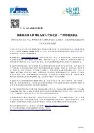
from the internal oscillator. With the oscillator source selected (see Figure 1), the remainder of the<br />
system clocking tree is configured by choosing the appropriate clock dividers (SYSDIV and PWMDIV).<br />
Figure 1. Clock Tree<br />
OSC1<br />
OSC2<br />
Main<br />
Osc<br />
1-8 MHz<br />
Internal<br />
Osc<br />
15 MHz<br />
÷4<br />
Application software chooses whether to use the PLL based on the value of the BYPASS signal.<br />
When the PLL is in use, it always outputs a 200-MHz clock signal, and when combined with the<br />
system divider (SYSDIV), generates the system clock.<br />
The clock that is fed into the PWM module is derived from the system clock. In applications requiring<br />
a slower PWM clock, the PWM divider (PWMDIV) can be applied to the clock signal be<strong>for</strong>e it reaches<br />
the PWM module.<br />
The ADC clock uses a constant divider that assumes a 200-MHz source, meaning that <strong>for</strong> the ADC<br />
clock to meet the required operating range of 14–18 MHz, the PLL must be enabled and used.<br />
Oscillator Sources<br />
OSCSRC a<br />
PLL<br />
(200 MHz<br />
output )<br />
OEN a<br />
XTAL a<br />
PWRDN a<br />
BYPASS a<br />
a. These are bit fields within the Run-Mode Clock Configuration (RCC) register.<br />
SYSDIV a<br />
PWMDIV a<br />
USESYSDIV a<br />
USEPWMDIV a<br />
System Clock<br />
PWM Clock<br />
Constant<br />
Divide<br />
(16.667 MHz output ) ADC Clock<br />
The main oscillator allows either a crystal or single-ended input clock signal. Cost-sensitive<br />
applications typically use an external crystal with the on-chip oscillator circuit since it is the most<br />
cost-effective solution. It is also possible to use the internal oscillator to clock the device after the<br />
boot process has completed.<br />
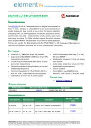
Crystal<br />
A crystal is used with the internal oscillator circuit by connecting the crystal to the OSC1 and OSC2<br />
pins of the <strong>Stellaris</strong> device (along with two capacitors) as shown in Figure 2 on page 5. The values of<br />
C1 and C2 are 15 pF <strong>for</strong> all crystals specified to work with the PLL (3.579545–8.192 MHz).<br />
June 24, 2009 4
Application Note <strong>Clocking</strong> Options <strong>for</strong> <strong>Stellaris</strong>® <strong>Family</strong> <strong>Microcontrollers</strong><br />
Figure 2. Crystal Source<br />
C1 C2<br />
OSC1<br />
OSC2<br />
<strong>Stellaris</strong> Device<br />
Single-Ended Clock<br />
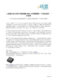
The second option <strong>for</strong> driving the main oscillator is using a single-ended clock source, such as a<br />
crystal oscillator, or even a function generator (<strong>for</strong> debug purposes). Using such a clock source does<br />
not require the on-chip oscillator circuit, and there<strong>for</strong>e does not require the OSC2 pin (see Figure 3 on<br />
page 6). The OSC2 pin is left floating in this configuration.<br />
When using a single-ended clock source with the PLL, one of the supported crystal frequencies must<br />
be used (see Table 1 on page 6).<br />
Internal Oscillator<br />
It is also possible to use the internal oscillator (or the internal oscillator divided by four) to clock the<br />
device once the boot process has completed. The oscillator source is changed by modifying the<br />
OSCSRC field of the RCC register in the System Control module.<br />
A major hindrance to using the internal oscillator is that its accuracy is only guaranteed to be within<br />
±50% of its ideal operating frequency of 15 MHz. Having such a large variance between devices<br />
practically eliminates the usefulness of the internal oscillator as a clock source in a real-world<br />
application. The primary use <strong>for</strong> the internal oscillator is <strong>for</strong> per<strong>for</strong>ming an internal clock check on the<br />
main oscillator source.<br />
June 24, 2009 5
Application Note <strong>Clocking</strong> Options <strong>for</strong> <strong>Stellaris</strong>® <strong>Family</strong> <strong>Microcontrollers</strong><br />
Figure 3. Single-Ended Source<br />
Using the PLL<br />
The PLL requires specific input clock frequencies in order to run at the desired 200 MHz. Crystals or<br />
single-ended sources ranging in frequency from 3.579545–8.192 MHz are supported. See Table 1<br />
<strong>for</strong> the full list of supported crystal frequencies.<br />
Table 1. Supported Crystal Frequencies<br />
Crystal Frequency (MHz)<br />
3.579545 MHz 5.12 MHz<br />
3.6864 MHz 6 MHz (reset value)<br />
4 MHz 6.144 MHz<br />
4.096 MHz 7.3728 MHz<br />
4.9152 MHz 8 MHz<br />
5 MHz 8.192 MHz<br />
OSC1<br />
OSC2<br />
<strong>Stellaris</strong> Device<br />
When a crystal or single-ended source with a supported frequency is used, the <strong>Stellaris</strong> device uses<br />
an internal look-up table to populate the PLL parameters in the XTAL to PLL Translation (PLLCFG)<br />
register. Using unsupported frequencies with the PLL can create faulty operation of the ADC module<br />
(if present).<br />
June 24, 2009 6
Application Note <strong>Clocking</strong> Options <strong>for</strong> <strong>Stellaris</strong>® <strong>Family</strong> <strong>Microcontrollers</strong><br />
Example 1. Configuring the PLL with the Driver Library<br />
This example shows how to configure the PLL using the <strong>Stellaris</strong>Ware® Peripheral Driver Library<br />
functions. The Driver Library is a software bundle of example drivers provided free by Texas<br />
Instruments. To download the software, visit the www.luminarymicro.com website.<br />
Configuring the PLL with the Driver Library is simple; it only requires a call to the SysCtlClockSet<br />
function. To configure the PLL to use a 6-MHz crystal and to run at a 20-MHz system clock, the<br />
function call is as shown in Code Segment 1.a.<br />
Code Segment 1.a. Configure PLL with SysCtlClockSet<br />
SysCtlClockSet(SYSCTL_SYSDIV_10 | SYSCTL_USE_PLL | SYSCTL_OSC_MAIN |<br />
SYSCTL_XTAL_6MHZ);<br />
The configuration parameters passed to the function are modifiable to fit the needs of the application.<br />
Typically, the only parameter that might change is the system divider since the oscillator frequency is<br />
usually fixed. The PLL is bypassed by changing the SYSCTL_USE_PLL parameter to<br />
SYSCTL_USE_OSC.<br />
Example 2. Configuring the PLL with Direct Register Writes<br />
When the Driver Library functions are not used, the PLL is configured using direct register writes to<br />
the Run-Mode Clock Configuration (RCC) register. The steps required to successfully change the<br />
PLL-based system clock are:<br />
1. Bypass the PLL and system clock divider by setting the BYPASS bit and clearing the USESYS bit in<br />
the RCC register. This configures the system to run off a “raw” clock source (using the main<br />
oscillator or internal oscillator) and allows <strong>for</strong> the new PLL configuration to be validated be<strong>for</strong>e<br />
switching the system clock to the PLL.<br />
2. Select the crystal value (XTAL) and oscillator source (OSCSRC), and clear the PWRDN and OE bits<br />
in RCC. Setting the XTAL field automatically pulls valid PLL configuration data <strong>for</strong> the appropriate<br />
crystal, and clearing the PWRDN and OE bits powers and enables the PLL and its output.<br />
3. Select the desired system divider (SYSDIV) and set the USESYS bit in RCC. The SYSDIV field<br />
determines the system frequency <strong>for</strong> the microcontroller.<br />
4. Wait <strong>for</strong> the PLL to lock by polling the PLLLRIS bit in the Raw Interrupt Status (RIS) register. If<br />
the PLL doesn’t lock, the configuration is invalid.<br />
5. Enable use of the PLL by clearing the BYPASS bit in RCC.<br />
Important: If the BYPASS bit is cleared be<strong>for</strong>e the PLL locks, it is possible to render the device<br />
unusable.<br />
Conclusion<br />
<strong>Stellaris</strong> microcontrollers must use an external oscillator source to boot, but can be configured to use<br />
the internal oscillator to clock the device if needed. For most applications, an inexpensive crystal is<br />
all that is required to clock the device, and the wide range of supported crystal frequencies allows<br />
flexibility in choosing an oscillator to use with the PLL.<br />
June 24, 2009 7
Application Note <strong>Clocking</strong> Options <strong>for</strong> <strong>Stellaris</strong>® <strong>Family</strong> <strong>Microcontrollers</strong><br />
References<br />
The following documents are available <strong>for</strong> download at www.luminarymicro.com:<br />
<strong>Stellaris</strong> microcontroller data sheet, Publication Number DS-LM3Snnn (where nnn is the part<br />
number <strong>for</strong> that specific <strong>Stellaris</strong> family device)<br />
<strong>Stellaris</strong>Ware® Driver Library<br />
<strong>Stellaris</strong>Ware® Driver Library User’s Manual, publication number SW-DRL-UG<br />
June 24, 2009 8
Application Note <strong>Clocking</strong> Options <strong>for</strong> <strong>Stellaris</strong>® <strong>Family</strong> <strong>Microcontrollers</strong><br />
Important Notice<br />
Texas Instruments Incorporated and its subsidiaries (TI) reserve the right to make corrections, modifications, enhancements,<br />
improvements, and other changes to its products and services at any time and to discontinue any product or service without notice.<br />
Customers should obtain the latest relevant in<strong>for</strong>mation be<strong>for</strong>e placing orders and should verify that such in<strong>for</strong>mation is current and<br />
complete. All products are sold subject to TI’s terms and conditions of sale supplied at the time of order acknowledgment.<br />
TI warrants per<strong>for</strong>mance of its hardware products to the specifications applicable at the time of sale in accordance with TI’s standard<br />
warranty. Testing and other quality control techniques are used to the extent TI deems necessary to support this warranty. Except where<br />
mandated by government requirements, testing of all parameters of each product is not necessarily per<strong>for</strong>med.<br />
TI assumes no liability <strong>for</strong> applications assistance or customer product design. Customers are responsible <strong>for</strong> their products and<br />
applications using TI components. To minimize the risks associated with customer products and applications, customers should provide<br />
adequate design and operating safeguards.<br />
TI does not warrant or represent that any license, either express or implied, is granted under any TI patent right, copyright, mask work<br />
right, or other TI intellectual property right relating to any combination, machine, or process in which TI products or services are used.<br />
In<strong>for</strong>mation published by TI regarding third-party products or services does not constitute a license from TI to use such products or<br />
services or a warranty or endorsement thereof. Use of such in<strong>for</strong>mation may require a license from a third party under the patents or other<br />
intellectual property of the third party, or a license from TI under the patents or other intellectual property of TI.<br />
Reproduction of TI in<strong>for</strong>mation in TI data books or data sheets is permissible only if reproduction is without alteration and is accompanied<br />
by all associated warranties, conditions, limitations, and notices. Reproduction of this in<strong>for</strong>mation with alteration is an unfair and deceptive<br />
business practice. TI is not responsible or liable <strong>for</strong> such altered documentation. In<strong>for</strong>mation of third parties may be subject to additional<br />
restrictions.<br />
Resale of TI products or services with statements different from or beyond the parameters stated by TI <strong>for</strong> that product or service voids all<br />
express and any implied warranties <strong>for</strong> the associated TI product or service and is an unfair and deceptive business practice. TI is not<br />
responsible or liable <strong>for</strong> any such statements.<br />
TI products are not authorized <strong>for</strong> use in safety-critical applications (such as life support) where a failure of the TI product would<br />
reasonably be expected to cause severe personal injury or death, unless officers of the parties have executed an agreement specifically<br />
governing such use. Buyers represent that they have all necessary expertise in the safety and regulatory ramifications of their applications,<br />
and acknowledge and agree that they are solely responsible <strong>for</strong> all legal, regulatory and safety-related requirements concerning their<br />
products and any use of TI products in such safety-critical applications, notwithstanding any applications-related in<strong>for</strong>mation or support<br />
that may be provided by TI. Further, Buyers must fully indemnify TI and its representatives against any damages arising out of the use of<br />
TI products in such safety-critical applications.<br />
TI products are neither designed nor intended <strong>for</strong> use in military/aerospace applications or environments unless the TI products are<br />
specifically designated by TI as military-grade or "enhanced plastic." Only products designated by TI as military-grade meet military<br />
specifications. Buyers acknowledge and agree that any such use of TI products which TI has not designated as military-grade is solely at<br />
the Buyer's risk, and that they are solely responsible <strong>for</strong> compliance with all legal and regulatory requirements in connection with such use.<br />
TI products are neither designed nor intended <strong>for</strong> use in automotive applications or environments unless the specific TI products are<br />
designated by TI as compliant with ISO/TS 16949 requirements. Buyers acknowledge and agree that, if they use any non-designated<br />
products in automotive applications, TI will not be responsible <strong>for</strong> any failure to meet such requirements.<br />
Following are URLs where you can obtain in<strong>for</strong>mation on other Texas Instruments products and application solutions:<br />
Products Applications<br />
Amplifiers amplifier.ti.com Audio www.ti.com/audio<br />
Data Converters dataconverter.ti.com Automotive www.ti.com/automotive<br />
DLP® Products www.dlp.com Broadband www.ti.com/broadband<br />
DSP dsp.ti.com Digital Control www.ti.com/digitalcontrol<br />
Clocks and Timers www.ti.com/clocks Medical www.ti.com/medical<br />
Interface interface.ti.com Military www.ti.com/military<br />
Logic logic.ti.com Optical Networking www.ti.com/opticalnetwork<br />
Power Mgmt power.ti.com Security www.ti.com/security<br />
<strong>Microcontrollers</strong> microcontroller.ti.com Telephony www.ti.com/telephony<br />
RFID www.ti-rfid.com Video & Imaging www.ti.com/video<br />
RF/IF and ZigBee® Solutions www.ti.com/lprf Wireless www.ti.com/wireless<br />
Mailing Address: Texas Instruments, Post Office Box 655303, Dallas, Texas 75265<br />
Copyright © 2009, Texas Instruments Incorporated<br />
June 24, 2009 9