Novel Power MOSFET Packaging Technology Doubles Power ...
Novel Power MOSFET Packaging Technology Doubles Power ...
Novel Power MOSFET Packaging Technology Doubles Power ...

Create successful ePaper yourself
Turn your PDF publications into a flip-book with our unique Google optimized e-Paper software.
<strong>Novel</strong> <strong>Power</strong> <strong>MOSFET</strong> <strong>Packaging</strong> <strong>Technology</strong> <strong>Doubles</strong> <strong>Power</strong> Density<br />
in Synchronous Buck Converters for Next Generation Microprocessors<br />
Abstract: This paper will introduce a novel power<br />
packaging technology developed by International<br />
Rectifier. This new packaging technology breaks<br />
ground in reducing package related losses and thus<br />
allowing designers to develop power supplies capable<br />
of meeting the demands of latest generation<br />
processors.<br />
I. INTRODUCTION<br />
Ever increasing demands for processing power<br />
has seen companies such as Intel and AMD relentlessly<br />
self-obsoleting themselves with faster and more powerful<br />
processor chips. These advances have, in general, been<br />
made through increases in the density of transistors that<br />
can be made on a given area of silicon. Consequently<br />
each successive processor generation employs millions<br />
more transistors than the previous. Whilst this boosts the<br />
number of operations that can be carried out every<br />
second, it also means that the current required by the<br />
processor to do this must increase. Current requirements<br />
for processors have increased exponentially over the last<br />
4-5 years and will soon be exceeding 100Amps in a<br />
number of processor applications.<br />
The challenge has been laid firmly at the door<br />
of the designers of the power supplies that service the<br />
processors. The common approach being taken is to<br />
employ multiphase converters to achieve the escalating<br />
current levels. For example, a four-phase converter<br />
running 25A per phase will supply 100A total. By<br />
running a phased converter and also increasing the<br />
operating frequency to satisfy the fast transient response<br />
required by processors running at higher clock speeds it<br />
is possible to reduce the size of the passive components<br />
used. This helps to ensure that the converter does not<br />
have to increase in size proportionally to the increase in<br />
current. However, this does mean that power densities on<br />
boards are increasing and the issue of cooling the power<br />
components within the converter is becoming a major<br />
issue.<br />
Reducing the losses exhibited and consequently<br />
power dissipated in the power components, e.g., the<br />
<strong>MOSFET</strong>s, has therefore been the focus of power supply<br />
Andrew Sawle, Carl Blake and Dragan Mariæ<br />
International Rectifier<br />
as presented at APEC 2002<br />
designers and component vendors alike. The evolution of<br />
power <strong>MOSFET</strong> silicon has radically cut both on-state<br />
and switching losses. However, power packaging is now<br />
becoming the limiting factor with the losses attributed to<br />
the packaging in some cases being greater than the losses<br />
from the silicon itself. Over the last couple of years there<br />
has been a move to reduce these package related losses.<br />
This paper introduces a new packaging technology,<br />
DirectFET , targeted for processor power converters.<br />
This new technology radically cuts conduction losses,<br />
whilst facilitating improved cooling regimes to enable<br />
the current and power levels required by the next<br />
generation of processors. The paper will describe this<br />
new technology and illustrate the advances made with<br />
examples from in circuit evaluations before addressing<br />
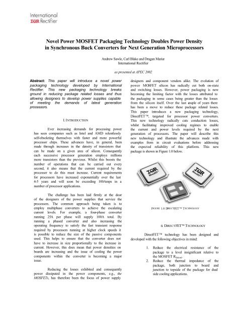
the expected reliability of this platform. This new<br />
package is shown in Figure 1.0 below.<br />
FIGURE 1.0 DIRECTFET TECHNOLOGY<br />
II. DIRECTFET TECHNOLOGY<br />
DirectFET technology has been designed and<br />
developed with the following objectives in mind:<br />
1. Reduce the electrical resistance of the<br />
package to a level insignificant relative to<br />
the <strong>MOSFET</strong> R ds(on).<br />
2. Reduce the thermal impedance of the<br />
package, both junction to board and<br />
junction to topside of the package for dual<br />
side cooling applications.
3. Facilitate simplified board layout and<br />
paralleling of devices.<br />
4. Enable the use of existing surface mount<br />
assembly lines and technology.<br />
In order to achieve points 1 and 2 above, the<br />
design of DirectFET technology has rationalised some<br />
of the concepts and materials that are commonly used in<br />
power packaging. This simplified approach is shown as a<br />
cross section in Figure 2.0.<br />
copper ‘drain’<br />
clip<br />
gate<br />
connection<br />
passivated die<br />
copper track<br />
on board<br />
die attach<br />
material<br />
source<br />
connection<br />
FIGURE 2.0 – CROSS SECTION OF DIRECTFET TECHNOLOGY<br />
The cross section in Figure 2.0 shows a<br />
<strong>MOSFET</strong> die with the source face of the die soldered<br />
directly to the printed circuit board. The drain connection<br />
is then made from the back of the die to the board<br />
through the use of a copper ‘can’ into which the die has<br />
been bonded. The facilitator in this scheme is a new<br />
proprietary passivation system developed by<br />
International Rectifier. This passivation is applied to a<br />
wafer that has a solderable top metal stack (rather than<br />
an aluminium top metal commonly used for wirebonded<br />
devices). It is then patterned to open out solderable areas<br />
on the surface of the die for the source and the gate<br />
connections. This allows the shape of the solder joints<br />
between the silicon and the circuit board to be closely<br />
controlled. The passivation has two very important roles<br />
to play:<br />
1. The passivation itself is unsolderable. This<br />
means that whilst allowing close control of<br />
the shape of the solder joints it also prohibits<br />
solder shorting between the gate and source<br />
contacts during the board mount process.<br />
2. The passivation provides environmental<br />
protection for the termination structure and<br />
gate busses on the die. It is resistant to<br />
moisture and ionic contamination that may be<br />
found on the board or in the solder flux, etc.<br />
With this passivation applied, the gate and source<br />
connections can be made directly between the circuit<br />
board and the die without any unnecessary leadframe or<br />
wirebonds in series with the conduction path. Since the<br />
construction of the <strong>MOSFET</strong> silicon used in DirectFET<br />
devices is not that of a flipchip, i.e not all the<br />
connections are on a single side of the die, the drain does<br />
require a ‘leadframe connection’ to complete the<br />
electrical circuit. The die is bonded into a copper clip or<br />
‘can’ using a silver filled epoxy and the finished, fully<br />
tested device can be board mounted in the same way as<br />
any conventional surface mount component.<br />
III. CONDUCTION PERFORMANCE<br />
The rationalised approach taken with<br />
DirectFET technology has greatly reduced the<br />
conduction path through the package and removed the<br />
high resistance elements. Figure 3.0 shows a comparison<br />
of the conduction paths of this new technology versus<br />
older SO -8 and newer Copperstrap SO-8 packages.<br />
The comparison shows that DirectFET technology has<br />
eliminated conduction paths and material interfaces<br />
which all add resistance in series with the silicon die.<br />
The effect is that the die free package resistance has been<br />
reduced to less than 200μΩ, a reduction of 86% over the<br />
SO-8 & approximately 74% over the Copperstrap SO-<br />
8. This reduction in the series resistance means that in an<br />
SO-8 outline typical R ds(on)values of 2mΩ are achievable.<br />
FIGURE 3.0 CONDUCTION PATHS FOR SO-8 (TOP), COPPERSTRAP SO-<br />
8 (MIDDLE) AND DIRECTFET TECHNOLOGY (BOTTOM)<br />
IV. THERMAL PERFORMANCE<br />
Whilst advances in conduction performance are<br />
key to increasing the current density in power converters,<br />
the issue of how to most effectively extract the heat from<br />
these converters and thus increase power density still<br />
applies. The direct nature of the coupling of the silicon to<br />
the board means that DirectFET technology has reduced<br />
the thermal resistance to the board. The thermal<br />
resistance from junction to board of a standard SO-8<br />
package is of the order of 20°C/W. However<br />
DirectFET technology reduces this to 1°C/W as the<br />
thermal resistance path runs through the top metal and
the board attach solder only. This more effective cooling<br />
to the board increases the amount of power that can be<br />
dissipated for a given junction temperature. However, as<br />
power densities increase there comes a point beyond<br />
which it is not possible to dissipate any more power into<br />
the board as it effectively becomes saturated. In order for<br />
power densities to increase further it is necessary to take<br />
the heat away from the power device but not through<br />
conduction into the board. Most surface mount<br />
components cater only for heat transfer into the board<br />
with minimal additional heat transfer to the ambient<br />
through radiation and convection. The construction of<br />
DirectFET technology has radically reduced the heat<br />
conduction path to the top side of the package. The<br />
thermal resistance from the junction of the <strong>MOSFET</strong> to<br />
the top of the package is 3°C/W compared to 25°C/W for<br />
an SO-8. Predominantly this reduction is borne from the<br />
lack of moulding compound. This now means that dual<br />
sided cooling can realistically be employed in order to<br />
pull even more heat out of the device and increase the<br />
amount of power that can be safely dissipated. Dual<br />
sided cooling can take a number of different forms, three<br />
of these are shown in Figure 4.0.<br />
FIGURE 4.0A – EXAMPLES OF DUAL SIDED COOLING<br />
FORCED AIR – NO HEATSINK<br />
FIGURE 4.0B – EXAMPLES OF DUAL SIDED COOLING<br />
FORCED AIR WITH ADDED HEATSINK<br />
FIGURE 4.0C – EXAMPLES OF DUAL SIDED COOLING<br />
SINKING TO CHASSIS THROUGH GAP-FILLING PAD<br />
By using dual sided cooling it is possible to<br />
reduce the total thermal resistance from junction to<br />
ambient to less than 12°C/W. This figure, when<br />
combined with the low conduction losses, means that it<br />
is possible to conduct greater than 30A with a single SO-<br />
8-outlined DirectFET technology device. The following<br />
section describes the results of in circuit evaluations that<br />
show the performance gains from the combined thermal<br />
and electrical improvements.<br />
V. IN CIRCUIT EVALUATION RESULTS<br />
In circuit performance evaluations have been<br />
carried out comparing the thermal and conduction<br />
performance of DirectFET technology to an SO-8 device<br />
utilizing the same silicon technology.<br />
The thermal images in Figure 6.0 show a<br />
comparison of a 30Vn SO-8 (IRF7822) and a DirectFET<br />
technology device (IRF6603) both in the synchronous<br />
FET socket in a synchronous buck converter, running at<br />
f sw=300kHz. In both cases the FETs are conducting 18A.<br />
FIGURE 6.0A – THERMAL IMAGES OF SO-8 RUNNING AT 300KHZ, 18A –<br />
TJ MEASURED AT 125°C IN SYNC-BUCK CIRCUIT<br />
FIGURE 6.0B – THERMAL IMAGES OF DIRECTFET TECHNOLOGY<br />
RUNNING AT 300KHZ, 18A – TJ MEASURED AT 75°C IN SYNC-BUCK<br />
CIRCUIT
The comparison shown in Figure 6.0 is with no<br />
dual sided cooling, heat only being transferred into the<br />
board. The SO-8 image shows the heat contours<br />
concentrated closely around the device, which means<br />
that minimal heat is being dissipated into the board<br />
leading to a high junction temperature. Conversely the<br />
DirectFET technology image shows the contours<br />
spreading more widely around the device showing more<br />
heat being transferred into the board. Consequently for<br />
the same current the DirectFET device is running 50°C<br />
cooler than the SO-8. In application this would either<br />
mean that the DirectFET device could be run cooler than<br />
the SO-8 and hence greater reliability could be expected<br />
or more likely a greater current would be conducted for<br />
the same junction temperature. A set of evaluations were<br />
conducted to determine the maximum current which<br />
could be conducted for a peak board temperature of<br />
105°C, a temperature commonly used as a limit in<br />
converter applications on FR4 substrate. The evaluations<br />
investigated cooling to board, 200 linear feet per minute<br />
airflow (no additional sink) and cooling to a chassis<br />
substitute. The results are shown in Table I.<br />
SO-8,<br />
IRF7822 in<br />
SyncFET<br />
socket<br />
DirectFET,<br />
IRF6603 in<br />
SyncFET<br />
socket<br />
%age<br />
increase<br />
in current<br />
No topside cooling 18A 24A 33%<br />
Constant 200LFM 20A 26A 30%<br />
Heatsink to<br />
substitute<br />
chassis<br />
22A 32A 45%<br />
TABLE I – MAXIMUM MEASURED CURRENT FOR DIFFERING COOLING<br />
SOLUTIONS<br />
In every case the DirectFET technology<br />
conducted at least 30% more current than the equivalent<br />
footprint SO-8 for the same cooling conditions. In fact,<br />
the DirectFET device case with the minimal cooling<br />
conditions conducted more current than the SO-8 with<br />
the best sinking solution.<br />
VI. EFFICIENCY MEASUREMENTS<br />
Improvements in both the thermal and<br />
conduction performance bring with them gains in<br />
converter efficiency. Measurements of efficiency were<br />
made for each of the cooling solutions shown in Table<br />
1.0 for varying load current. The efficiency curves for<br />
DirectFET technology parts in both the synchronous<br />
FET socket and the control FET socket, both cooled and<br />
uncooled versus uncooled SO-8 devices are shown in<br />
Figure 7.0.<br />
Efficiency [%]<br />
94<br />
92<br />
90<br />
88<br />
86<br />
84<br />
82<br />
80<br />
78<br />
76<br />
74<br />
72<br />
70<br />
68<br />
IRF6603/IRF6604 (200LFM, heatsink)<br />
IRF6603/IRF6604 (still air,no heatsink)<br />
IRF7822/IRF7811W (still air, no heatsink)<br />
105°C max board temp reached<br />
2 4 6 8 10 12 14 16 18 20 22 24 26 28 30 32 34 36<br />
Load Current [A]<br />
FIGURE 7.0 – EFFICIENCY CHART COMPARING DIRECTFET<br />
(IRF6603/4) WITH SO-8 (IRF7822/11) IN SYNCRONOUS RECTIFIER<br />
CIRCUIT AT 300KHZ<br />
The measurements in Figure 7.0 show the<br />
converter efficiency versus load current. In all cases the<br />
measurements were stopped at a current level where the<br />
maximum board temperature of 105°C was reached. It<br />
can be seen that at 18A the uncooled DirectFET devices<br />
give a four percentage point improvement in converter<br />
efficiency over the uncooled SO -8s. By heatsinking the<br />
DirectFET devices to a chassis substitute a further one<br />
percentage point improvement in converter efficiency<br />
was achieved at 18A. Alternatively the load current<br />
could be increased by 5.5A for the same converter<br />
efficiency, an increase of 30%. An additional point to<br />
note is that the improved cooling means that the<br />
converter could be run to 35A before the board<br />
temperature reached the 105°C limit. It is also important<br />
to note that the circuit used here was optimised for SO-8<br />
devices. Namely, optimising the circuit for the<br />
DirectFET devices (e.g., using a high current inductor)<br />
would render noticeably higher efficiency at high current<br />
levels.<br />
VI. CURRENT DENSITY INCREASES<br />
The in circuit evaluations have shown that 30A<br />
is achievable using a single DirectFET technology pair<br />
(synchronous and control FET) whilst maintaining a<br />
maximum board temperature of 105°C. In order to<br />
achieve 30A it would be necessary to parallel two or<br />
more SO -8 devices in each of the synchronous and<br />
control FET sockets. Table II below shows a DirectFET<br />
technology versus SO-8 comparison of required board<br />
area and the resulting amps/in 2 for 30A per phase<br />
converters. To make a fair comparison it is assumed that<br />
both the DirectFET devices and the SO -8s are heatsinked<br />
to a chassis. In practice it would not be sensible to sink<br />
the SO-8 to a chassis in this application as the
performance gain through doing so would still not mean<br />
that a single device could be used.<br />
<strong>Power</strong> Supply Solution Area [in 2 ] Amps/in 2<br />
SO-8 2-phase solution 5.54 10.82<br />
SO-8 4-phase solution 10.45 11.48<br />
DirectFET 2 –phase solution 2.77 21.67<br />
DirectFET 4 –phase solution 4.90 24.49<br />
TABLE II. CURRENT DENSITIES FOR A 30A/PHASE SYNCHRONOUS BUCK<br />
CONVERTER<br />
Table II shows that in both the two phase and<br />
the four phase solutions the current density has been<br />
doubled through the use of DirectFET technology. Also,<br />
as power is a function of current, the power density is<br />
also doubled in the converters using the DirectFET<br />
devices whilst still not exceeding the specified 105°C<br />
maximum board temperature.<br />
VII. RELIABILITY<br />
New technologies that appear to be different to<br />
those that have preceded them sometimes cause concern<br />
over reliability. Consequently DirectFET technology has<br />
undergone extensive reliability testing to ensure that<br />
there will be no issues when it is working in applications<br />
in the field. The testing completed has included those<br />
tests that are commonly undertaken on power <strong>MOSFET</strong><br />
components, as well as additional testing to show<br />
ruggedness and fitness for use.<br />
In order to ensure that material sets used do not<br />
interact badly with the silicon die and that they also<br />
protect the die from the environment, bias testing is<br />
undertaken. High temperature reverse bias; temperature,<br />
humidity and bias; and high temperature gate bias have<br />
all been completed on large sample sizes (greater than<br />
200) for 1000 hours with no failures. Additionally,<br />
thermal cycling tests including temperature cycling on<br />
board (-40 to +125°C) for 500 cycles and power cycling<br />
to 8000 cycles have been completed with zero failures.<br />
These tests are the standard tests that are completed by<br />
most vendors to qualify new power components. Further<br />
work has been undertaken to allay any mechanical<br />
strength concerns.<br />
VIIa Bend strength measurements<br />
An example of the additional testing that has<br />
been completed is bend strength measurement.<br />
Comparisons have been made with ceramic capacitors in<br />
order to determine how DirectFET technology compares<br />
to other components that it is likely to share a board<br />
with. There are standard tests to determine the strength<br />
of ceramic capacitors and these have been used on<br />
DirectFET devices. In all cases ceramic capacitors have<br />
also been tested as a control.<br />
Bend strength measurements are simple in<br />
methodology - mount a device onto a board of predetermined<br />
dimensions and then deflect and bend the<br />
Survival Rate<br />
board about the point where the device is mounted.<br />
Continuous monitoring of gate leakage & gate threshold<br />
voltage allows the point of failure versus deflection to be<br />
determined. A photograph of the setup is shown in<br />
Figure 8.0.<br />
FIGURE 8.0. BEND STRENGTH MEASUREMENT SETUP (DIRECTFET<br />
DEVICE ON UNDERSIDE OF BOARD)<br />
This testing was completed on DirectFET<br />
technology, investigating:<br />
orientation of device on board<br />
device on front and back of board<br />
thickness of board<br />
thickness of board attach solder<br />
composition of board attach solder<br />
In all cases the ceramic capacitors failed (based on a 20%<br />
shift in capacitance) at a lower deflection than the<br />
DirectFET devices. This is shown in the set of mortality<br />
curves shown in Figure 9.0.<br />
100%<br />
80%<br />
60%<br />
40%<br />
20%<br />
Hex3.0 DirectFET(L)<br />
Hex3.0 DirectFET (T)<br />
1812 Ceramic Capacitor<br />
Hex3.0 DirectFET (Front Side)<br />
The shaded area signifies<br />
the point at which the boards<br />
failed. No components<br />
survived beyond this.<br />
0%<br />
0 5 10 15 20 25<br />
Deflection (mm)<br />
FIGURE 9.0 – MORTALITY CURVES COMPARI NG DIRECTFET TEC<br />
HNOLOGY WITH CERAMIC CAPACITORS
In most of the tests the DirectFET devices did not fail<br />
catastrophically until the boards themselves snapped.<br />
VIIb Compression resistance<br />
In specifying that the device can be used in systems using<br />
dual sided cooling it is necessary to determine its fitness<br />
for this purpose. It was therefore necessary to investigate<br />
DirectFET technology’s resistance to pressure. This was<br />
to ensure that heat sinking that applies a force to the top<br />
of the package would not result in damage. The testing<br />
again utilised continuous monitoring of gate leakage and<br />
gate threshold voltage whilst an increasing force was<br />
applied to the top of the package. No shifts in the<br />
monitored variables were observed below 500N. This<br />
figure is well above any force that would be used for<br />
mounting a heat sink. Typically these would not exceed<br />
100N.<br />
VIII. SUMMARY AND CONCLUSION<br />
This paper has presented DirectFET technology,<br />
which is targeted at facilitating the current and power<br />
densities required by future power supplies for next<br />
generation microprocessors. Improvements in thermal<br />
and electrical conduction have been made through the<br />
rationalization of packaging design and tailoring it to the<br />
existing and future requirements of the synchronous<br />
buck converters used for processor power. These<br />
converters need to supply greater than 100A to the<br />
processors that they support. Multi-phase converters<br />
enable these high currents although each phase is still<br />
required to supply greater than 25A. Through in-circuit<br />
evaluations this paper has shown that the use of<br />
DirectFET technology facilitates greater than 30A per<br />
phase using a single device in each of the synchronous<br />
and control FET sockets in the converter. Alternate<br />
packaging platforms (e.g. SO-8) would require the<br />
paralleling of devices. Compared to existing best<br />
performing SO-8 devices DirectFET technology<br />
achieves double the current and power density whilst<br />
proving to be a reliable platform with fitness for purpose.