Novel Power MOSFET Packaging Technology Doubles Power ...
Novel Power MOSFET Packaging Technology Doubles Power ...
Novel Power MOSFET Packaging Technology Doubles Power ...

You also want an ePaper? Increase the reach of your titles
YUMPU automatically turns print PDFs into web optimized ePapers that Google loves.
The comparison shown in Figure 6.0 is with no<br />
dual sided cooling, heat only being transferred into the<br />
board. The SO-8 image shows the heat contours<br />
concentrated closely around the device, which means<br />
that minimal heat is being dissipated into the board<br />
leading to a high junction temperature. Conversely the<br />
DirectFET technology image shows the contours<br />
spreading more widely around the device showing more<br />
heat being transferred into the board. Consequently for<br />
the same current the DirectFET device is running 50°C<br />
cooler than the SO-8. In application this would either<br />
mean that the DirectFET device could be run cooler than<br />
the SO-8 and hence greater reliability could be expected<br />
or more likely a greater current would be conducted for<br />
the same junction temperature. A set of evaluations were<br />
conducted to determine the maximum current which<br />
could be conducted for a peak board temperature of<br />
105°C, a temperature commonly used as a limit in<br />
converter applications on FR4 substrate. The evaluations<br />
investigated cooling to board, 200 linear feet per minute<br />
airflow (no additional sink) and cooling to a chassis<br />
substitute. The results are shown in Table I.<br />
SO-8,<br />
IRF7822 in<br />
SyncFET<br />
socket<br />
DirectFET,<br />
IRF6603 in<br />
SyncFET<br />
socket<br />
%age<br />
increase<br />
in current<br />
No topside cooling 18A 24A 33%<br />
Constant 200LFM 20A 26A 30%<br />
Heatsink to<br />
substitute<br />
chassis<br />
22A 32A 45%<br />
TABLE I – MAXIMUM MEASURED CURRENT FOR DIFFERING COOLING<br />
SOLUTIONS<br />
In every case the DirectFET technology<br />
conducted at least 30% more current than the equivalent<br />
footprint SO-8 for the same cooling conditions. In fact,<br />
the DirectFET device case with the minimal cooling<br />
conditions conducted more current than the SO-8 with<br />
the best sinking solution.<br />
VI. EFFICIENCY MEASUREMENTS<br />
Improvements in both the thermal and<br />
conduction performance bring with them gains in<br />
converter efficiency. Measurements of efficiency were<br />
made for each of the cooling solutions shown in Table<br />
1.0 for varying load current. The efficiency curves for<br />
DirectFET technology parts in both the synchronous<br />
FET socket and the control FET socket, both cooled and<br />
uncooled versus uncooled SO-8 devices are shown in<br />
Figure 7.0.<br />
Efficiency [%]<br />
94<br />
92<br />
90<br />
88<br />
86<br />
84<br />
82<br />
80<br />
78<br />
76<br />
74<br />
72<br />
70<br />
68<br />
IRF6603/IRF6604 (200LFM, heatsink)<br />
IRF6603/IRF6604 (still air,no heatsink)<br />
IRF7822/IRF7811W (still air, no heatsink)<br />
105°C max board temp reached<br />
2 4 6 8 10 12 14 16 18 20 22 24 26 28 30 32 34 36<br />
Load Current [A]<br />
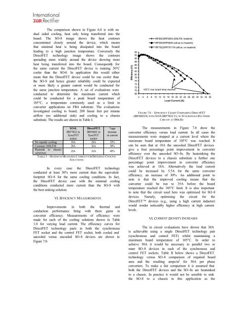
FIGURE 7.0 – EFFICIENCY CHART COMPARING DIRECTFET<br />
(IRF6603/4) WITH SO-8 (IRF7822/11) IN SYNCRONOUS RECTIFIER<br />
CIRCUIT AT 300KHZ<br />
The measurements in Figure 7.0 show the<br />
converter efficiency versus load current. In all cases the<br />
measurements were stopped at a current level where the<br />
maximum board temperature of 105°C was reached. It<br />
can be seen that at 18A the uncooled DirectFET devices<br />
give a four percentage point improvement in converter<br />
efficiency over the uncooled SO -8s. By heatsinking the<br />
DirectFET devices to a chassis substitute a further one<br />
percentage point improvement in converter efficiency<br />
was achieved at 18A. Alternatively the load current<br />
could be increased by 5.5A for the same converter<br />
efficiency, an increase of 30%. An additional point to<br />
note is that the improved cooling means that the<br />
converter could be run to 35A before the board<br />
temperature reached the 105°C limit. It is also important<br />
to note that the circuit used here was optimised for SO-8<br />
devices. Namely, optimising the circuit for the<br />
DirectFET devices (e.g., using a high current inductor)<br />
would render noticeably higher efficiency at high current<br />
levels.<br />
VI. CURRENT DENSITY INCREASES<br />
The in circuit evaluations have shown that 30A<br />
is achievable using a single DirectFET technology pair<br />
(synchronous and control FET) whilst maintaining a<br />
maximum board temperature of 105°C. In order to<br />
achieve 30A it would be necessary to parallel two or<br />
more SO -8 devices in each of the synchronous and<br />
control FET sockets. Table II below shows a DirectFET<br />
technology versus SO-8 comparison of required board<br />
area and the resulting amps/in 2 for 30A per phase<br />
converters. To make a fair comparison it is assumed that<br />
both the DirectFET devices and the SO -8s are heatsinked<br />
to a chassis. In practice it would not be sensible to sink<br />
the SO-8 to a chassis in this application as the