An optical fibre based evanescent wave sensor to monitor the ...
An optical fibre based evanescent wave sensor to monitor the ...
An optical fibre based evanescent wave sensor to monitor the ...

You also want an ePaper? Increase the reach of your titles
YUMPU automatically turns print PDFs into web optimized ePapers that Google loves.
Abstract<br />
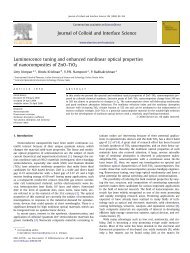
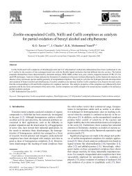
<strong>An</strong> <strong>optical</strong> <strong>fibre</strong> <strong>based</strong> <strong>evanescent</strong> <strong>wave</strong> <strong>sensor</strong> <strong>to</strong> moni<strong>to</strong>r<br />
<strong>the</strong> deposition rate of thin films<br />
Deepa Jose, M. Shelly John, P. Radhakrishnan*, V.P.N. Nampoori, C.P.G. Vallabhan<br />
International School of Pho<strong>to</strong>nics, Cochin University of Science and Technology, Cochin 682 022, India<br />
Received 27 Oc<strong>to</strong>ber 1997; accepted 23 January 1998<br />
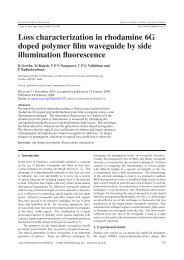
A novel <strong>fibre</strong> optic <strong>sensor</strong> for <strong>the</strong> in situ measurement of <strong>the</strong> rate of deposition of thin films has been developed. Evanescent <strong>wave</strong> in <strong>the</strong><br />
uncladded portion of a multimode <strong>fibre</strong> is utilised for this <strong>sensor</strong> development. In <strong>the</strong> present paper we demonstrate how this <strong>sensor</strong> is useful<br />
for <strong>the</strong> moni<strong>to</strong>ring of <strong>the</strong> deposition rate of polypyrrole thin films, deposited by an AC plasma polymerisation method. This technique is<br />
simple, accurate and highly sensitive compared with existing techniques. © 1998 Elsevier Science S.A. All rights reserved<br />
Keywords: Optical spectroscopy; Plasma processing and deposition; Polymers; Sensors<br />
1. Introduction<br />
Fibre optic <strong>sensor</strong>s (FOSs) play a major role in <strong>the</strong> field of<br />
pho<strong>to</strong>nics as applied <strong>to</strong> research and industry. Many of <strong>the</strong>ir<br />
attractive features have caused <strong>the</strong>m <strong>to</strong> earn a prominent<br />
place in <strong>the</strong> forefront of pho<strong>to</strong>nics technology. Recent<br />
works in this emerging area prove that <strong>the</strong> FOSs have a<br />
remarkable ability <strong>to</strong> measure physical and chemical variables<br />
with unprecedented sensitivity and accuracy [1–4].<br />
Also, <strong>the</strong>re exists enormous potential for FOSs <strong>to</strong> be developed<br />
as an important technique for on-line measurements.<br />
Quite a few FOSs have been developed in recent times for<br />
<strong>the</strong> moni<strong>to</strong>ring of a variety of physical parameters [5]. The<br />
present paper discusses <strong>the</strong> design and implementation<br />
of a simple FOS for moni<strong>to</strong>ring <strong>the</strong> deposition rate of thin<br />
films.<br />
Different techniques such as resistance moni<strong>to</strong>rs, capacitance<br />
moni<strong>to</strong>rs, quartz crystal moni<strong>to</strong>rs, radiation absorption<br />
methods, pho<strong>to</strong>metric methods etc., are used at<br />
present for <strong>the</strong> deposition rate moni<strong>to</strong>ring [6]. Each method<br />
is well known for its merits and demerits. The film resistance<br />
method is applicable only <strong>to</strong> metallic and low resistivity<br />
semiconduc<strong>to</strong>r films. For structurally discontinuous<br />
films (10 nm), this method cannot be used. The capaci-<br />
* Corresponding author. E-mail: pho<strong>to</strong>nix@md2.vsnl.net.in<br />
0040-6090/98/$19.00 © 1998 Elsevier Science S.A. All rights reserved<br />
PII S0040-6090(98)00498-2<br />
Thin Solid Films 325 (1998) 264–267<br />
tance moni<strong>to</strong>r method is not very sensitive and it may be<br />
subject <strong>to</strong> spurious effects due <strong>to</strong> stray electrical charges in<br />
<strong>the</strong> vapour and in <strong>the</strong> vacuum chamber. The maximum sensitivity<br />
of a quartz crystal moni<strong>to</strong>r is limited by variations in<br />
<strong>the</strong> crystal frequency due <strong>to</strong> temperature, oscilla<strong>to</strong>r drive<br />
level, and changes in <strong>the</strong> oscilla<strong>to</strong>r circuit. Use of suitable<br />
radiation shields and also water cooling of <strong>the</strong> crystal holder<br />
are needed in this case. In <strong>the</strong> radiation absorption method,<br />
<strong>the</strong> absorption in discontinuous films is strongly influenced<br />
by <strong>the</strong> granular nature of films, but it may still be used for<br />
relative measurement of <strong>the</strong> average film thickness. The<br />
pho<strong>to</strong>metric method uses <strong>the</strong> oscilla<strong>to</strong>ry nature of <strong>the</strong> interference<br />
effect of a reflected or transmitted beam from <strong>the</strong><br />
film–substrate combination during deposition. This method<br />
is mainly used for moni<strong>to</strong>ring and controlling <strong>the</strong> deposition<br />
of multilayer dielectric films. Optical methods have <strong>the</strong><br />
advantage that <strong>the</strong>y are generally non-contact in nature<br />
and hence in situ measurements can be performed very<br />
conveniently without breaking <strong>the</strong> vacuum. Optical <strong>fibre</strong><br />
<strong>based</strong> techniques have <strong>the</strong> added advantage that <strong>the</strong> possibility<br />
of remote measurement is quite inherent.<br />
Although, this paper deals with <strong>the</strong> measurement of <strong>the</strong><br />
deposition rate of thin films of an organic material (polypyrrole)<br />
which is produced by AC plasma polymerisation,<br />
<strong>the</strong> technique described here can be applied in general <strong>to</strong><br />
any deposition method.
2. Theory<br />
It is well known that <strong>the</strong> guided light in a <strong>fibre</strong> <strong>wave</strong>guide<br />
penetrates in<strong>to</strong> <strong>the</strong> cladding <strong>to</strong> a distance of a few <strong>wave</strong>lengths<br />
as <strong>the</strong> <strong>evanescent</strong> tail of <strong>the</strong> <strong>wave</strong>guide mode. The<br />
power transmitted by an <strong>optical</strong> <strong>fibre</strong>, <strong>the</strong> cladding of which<br />
has been replaced locally by an absorbing medium may be<br />
written as [7]<br />
P(z)=P(o)exp(−gz) (1)<br />
where z is <strong>the</strong> length of <strong>the</strong> uncladded region of <strong>the</strong> <strong>fibre</strong>,<br />
P(o) is <strong>the</strong> power transmitted in <strong>the</strong> absence of an absorbing<br />
species, and g is <strong>the</strong> <strong>evanescent</strong> absorption coefficient. The<br />
coefficient may be related <strong>to</strong> bulk absorption coefficient a<br />
when all bound modes are launched. In this case <strong>the</strong> fraction<br />
of power (r) outside <strong>the</strong> core is given by<br />
r = 4<br />
<br />
2<br />
(2)<br />
3V<br />
where V is <strong>the</strong> normalised frequency parameter of <strong>the</strong> <strong>fibre</strong>.<br />
For a <strong>fibre</strong> of core radius a and numerical aperture NA,<br />
V = 2pa/l NA, where l is <strong>the</strong> <strong>wave</strong>length of <strong>the</strong> propagating<br />
light. Hence Eq. (1) becomes<br />
P(z)=P(o)exp(−raz) (3)<br />
so that <strong>the</strong> <strong>evanescent</strong> absorbance, log P(o)/P(z), of an<br />
uncladded <strong>fibre</strong> of length L surrounded by a medium of<br />
bulk absorption coefficient a is given by<br />
A = gL raL<br />
= (4)<br />
2X303 2X303<br />
where A is proportional <strong>to</strong> laL/a NA. The above equation<br />
predicts that <strong>the</strong> <strong>evanescent</strong> absorbance depends linearly on<br />
D. Jose et al. / Thin Solid Films 325 (1998) 264–267<br />
<strong>the</strong> exposed <strong>fibre</strong> length L, <strong>the</strong> bulk absorption coefficient a<br />
and inversely on <strong>the</strong> numerical aperture (NA).<br />
In <strong>the</strong> absence of <strong>evanescent</strong> <strong>wave</strong> absorption, <strong>the</strong> guidance<br />
of light through <strong>the</strong> uncladded region gets modulated<br />
by <strong>the</strong> changes in <strong>the</strong> refractive index of <strong>the</strong> coupling medium.<br />
The input <strong>optical</strong> power coupled through an uncladded<br />
region of <strong>the</strong> <strong>fibre</strong> <strong>to</strong> <strong>the</strong> output port would vary with <strong>the</strong><br />
dielectric constant (m = n 2 m) of <strong>the</strong> medium surrounding<br />
<strong>the</strong> uncladded region. For a Lambertian source, <strong>the</strong> output<br />
power is given by [8]<br />
P = P(o) n21 − n 2 m<br />
n2 1 − n2 (5)<br />
2<br />
where P(o) is <strong>the</strong> <strong>to</strong>tal guided power in <strong>the</strong> <strong>fibre</strong> and n1, n2<br />
and nm are <strong>the</strong> refractive indices of <strong>the</strong> core, cladding and<br />
<strong>the</strong> medium surrounding <strong>the</strong> uncladded region, respectively.<br />
3. Experimental details<br />
Polypyrrole is prepared directly from its monomer vapour<br />
by a low frequency AC (50 Hz) plasma polymerisation<br />
process. A schematic experimental set-up is given in Fig.<br />
1. The sensing <strong>fibre</strong> with its cladding removed from a region<br />
of certain length is passed through <strong>the</strong> inter-electrode<br />
region. A glass substrate on which <strong>the</strong> thin film has <strong>to</strong> be<br />
deposited is also kept near <strong>the</strong> <strong>fibre</strong>. A diode laser (4.25<br />
mW, at 670 nm) is focused on<strong>to</strong> one end of <strong>the</strong> <strong>fibre</strong> and<br />
<strong>the</strong> output power from <strong>the</strong> o<strong>the</strong>r end is measured using a<br />
commercial <strong>fibre</strong> optic powermeter (Meggar OTP 510).<br />
First, <strong>the</strong> system is pumped down <strong>to</strong> about 10 −3 Torr.<br />
Then <strong>the</strong> voltage is applied between <strong>the</strong> electrodes <strong>to</strong> pro-<br />
Fig. 1. Schematic of <strong>the</strong> experimental set-up. W, window; E, electrode; s, sprayer; u, uncladded region of <strong>the</strong> <strong>fibre</strong>.<br />
265
266 D. Jose et al. / Thin Solid Films 325 (1998) 264–267<br />
duce <strong>the</strong> plasma and <strong>the</strong> monomer is sprayed in<strong>to</strong> <strong>the</strong> interelectrode<br />
region by means of a sprayer by carefully controlling<br />
<strong>the</strong> flow rate using a needle valve. The pressure (P),<br />
discharge voltage (V), <strong>the</strong> flow rate (R) and <strong>the</strong> distance<br />
between <strong>the</strong> electrodes (d) are adjusted such that a solid<br />
coating of polypyrrole is obtained on <strong>the</strong> glass plate [9] as<br />
well as on <strong>the</strong> uncladded <strong>fibre</strong>. The <strong>evanescent</strong> <strong>wave</strong> coupling<br />
of this medium surrounding <strong>the</strong> uncladded region<br />
brings about a change in <strong>the</strong> output intensity of <strong>the</strong> <strong>fibre</strong><br />
as deposition proceeds.<br />
4. Results and discussions<br />
The output power from <strong>the</strong> <strong>optical</strong> <strong>fibre</strong> is measured at<br />
regular intervals of time during <strong>the</strong> deposition of film on <strong>the</strong><br />
uncladded region. Fig. 2 is a typical output power versus<br />
time plot for <strong>the</strong> <strong>sensor</strong> with an uncladded length of 0.06 m<br />
for a particular combination of pressure, voltage, flow rate<br />
and inter-electrode distance (P = 10 −3 Torr, V = 550 V, R<br />
(position of needle valve) = 70 units, d = 0.035 m). As was<br />
expected, <strong>the</strong> graph showed two distinct regions, viz. an<br />
almost linearly decreasing region and a saturation region..<br />
From <strong>the</strong> linear portion of <strong>the</strong> P versus t graph, dP/dt is<br />
calculated. The system is calibrated by measuring <strong>the</strong> thickness<br />
of a few films prepared for different time durations<br />
within <strong>the</strong> linear range. The slope of <strong>the</strong> thickness (x) versus<br />
time (t) graph yields dx/dt. In <strong>the</strong> linear region, <strong>the</strong> rate of<br />
change of transmitted power is proportional <strong>to</strong> <strong>the</strong> rate of<br />
deposition.<br />
iXeX<br />
Fig. 2. Typical plot of output power variation with time.<br />
dP dx<br />
∝<br />
dt dt<br />
dx dP<br />
or = K<br />
dt dt<br />
The value of K is evaluated for a set of experimental conditions<br />
and is found <strong>to</strong> be 0.12 nm/mW. This enables us <strong>to</strong><br />
(6)<br />
calibrate <strong>the</strong> <strong>sensor</strong>. Knowing <strong>the</strong> value of K and by moni<strong>to</strong>ring<br />
<strong>the</strong> output power variation with time, <strong>the</strong> deposition<br />
rate dx/dt and hence <strong>the</strong> thickness x at any instant t during<br />
<strong>the</strong> deposition can be evaluated.<br />
The decrease in <strong>the</strong> output power with thin film deposition<br />
can be attributed ei<strong>the</strong>r <strong>to</strong> <strong>the</strong> absorption of <strong>the</strong> laser<br />
radiation by <strong>the</strong> deposited polypyrrole or due <strong>to</strong> refractive<br />
index variation. The absorption spectrum of polypyrrole<br />
obtained using a Hitachi-340 model UV-VIS-NIR spectropho<strong>to</strong>meter<br />
within <strong>the</strong> spectral range 200–800 nm (Fig. 3)<br />
shows that <strong>the</strong> material does not have much absorption at<br />
<strong>the</strong> laser <strong>wave</strong>length (670 nm) used. So <strong>the</strong> decrease in<br />
output is mainly due <strong>to</strong> <strong>the</strong> refractive index variation. That<br />
is, as <strong>the</strong> material gets coated on <strong>the</strong> <strong>fibre</strong>, <strong>the</strong> air cladding<br />
gets replaced by <strong>the</strong> polypyrrole cladding, which has a<br />
higher refractive index than air. Due <strong>to</strong> <strong>the</strong> decrease in <strong>the</strong><br />
index difference between <strong>the</strong> core and <strong>the</strong> deposited polypyrrole,<br />
which acts as cladding, <strong>the</strong> acceptance angle for<br />
<strong>the</strong> portion of <strong>the</strong> <strong>fibre</strong> and hence <strong>the</strong> numerical aperture<br />
decreases and <strong>the</strong> coupled power correspondingly gets<br />
reduced while deposition progresses. When a polypyrrole<br />
cladding of a particular thickness is formed, fur<strong>the</strong>r increase<br />
in thickness will not have any effect on <strong>the</strong> output<br />
power, and so <strong>the</strong> output power remains constant leading <strong>to</strong><br />
saturation.<br />
Within <strong>the</strong> limits of accuracy of thickness measurement,<br />
we obtained an output variation of 1 mW corresponding <strong>to</strong><br />
0.1 nm deposition. Keeping <strong>the</strong> pressure, voltage and<br />
<strong>sensor</strong> length a constant, an increase in <strong>the</strong> flow rate is<br />
found <strong>to</strong> decrease <strong>the</strong> output power faster showing a deposition<br />
rate increase. This is a confirmation of <strong>the</strong> observed<br />
fact that <strong>the</strong> deposition rate increases with increasing flow<br />
rate, passes through a maximum and <strong>the</strong>n decreases slightly<br />
[9].<br />
Acknowledgements<br />
Fig. 3. Absorption spectrum of polypyrrole.<br />
Financial assistance from Science, Technology and<br />
Environment Department (STED), Government of Kerala<br />
is acknowledged. M.S.J. is grateful <strong>to</strong> UGC (New Delhi)<br />
for research fellowship. The authors acknowledge <strong>the</strong><br />
timely help from Mr. Riju C. Issac.
References<br />
[1] A. Bouzid, M.A.G. Abushagur, Z. He, S.E. Kosten, Opt. Eng. 33<br />
(1994) 1074.<br />
[2] C.-T. Shyu, L. Wang, J. Light<strong>wave</strong> Technol. 12 (1994) 2040.<br />
[3] M.A. Arnold, <strong>An</strong>al. Chem. 64 (1992) 1015A.<br />
[4] V. Ruddy, B.D. MacCraith, J.A. Murphy, J. Appl. Phys. 67 (1990)<br />
6070.<br />
D. Jose et al. / Thin Solid Films 325 (1998) 264–267<br />
267<br />
[5] S.M. Klainer, J.R. Thomas, J.C. Francis, Sens. Actuat. B 11 (1993)<br />
81.<br />
[6] K.L. Chopra, Thin Film Phenomena, McGraw-Hill, New York, 1969.<br />
[7] P. Radhakrishnan, V.P.N. Nampoori, C.P.G. Vallabhan, Opt. Eng. 32<br />
(1993) 692.<br />
[8] A. Kumar, T.V.B. Subrahmanyam, A.D. Sharma, K. Thyagarajan,<br />
B.P. Pal, I.C. Goyal, Electron. Lett. 20 (1984) 534.<br />
[9] H. Biederman, Thin Solid Films 86 (1981) 125.