Mix Rack Guide (PDF) - Digidesign
Mix Rack Guide (PDF) - Digidesign
Mix Rack Guide (PDF) - Digidesign

Create successful ePaper yourself
Turn your PDF publications into a flip-book with our unique Google optimized e-Paper software.
PN 9321-58463-00 REV A 01/08<br />
<strong>Mix</strong> <strong>Rack</strong><br />
<strong>Guide</strong><br />
For VENUE Systems<br />
<strong>Digidesign</strong><br />
2001 Junipero Serra Boulevard<br />
Daly City, CA 94014-3886 USA<br />
tel: 650·731·6300<br />
fax: 650·731·6399<br />
Technical Support (USA)<br />
tel: 650·731·6100<br />
fax: 650·731·6375<br />
Product Information (USA)<br />
tel: 650-731-6102<br />
International Offices<br />
Visit the <strong>Digidesign</strong> website<br />
for contact information<br />
Website<br />
www.digidesign.com
Copyright<br />
© 2008 Avid Technology, Inc. All rights reserved. This guide may not be<br />
duplicated in part or in whole without the prior written consent of Avid<br />
Technology, Inc.<br />
Avid, <strong>Digidesign</strong>, D-Show, and Pro Tools are trademarks or registered<br />
trademarks of Avid Technology, Inc. in the U.S. and/or other countries. All other<br />
trademarks contained herein are the property of their respective owners.<br />
Product features, specifications, system requirements, and availability are<br />
subject to change without notice.<br />
PN 9321-58463-00 REV A 01/08<br />
Warning<br />
This product contains chemicals, including lead, known to the State of California<br />
to cause cancer and birth defects or other reproductive harm. Wash hands after<br />
handling.<br />
Communications & Safety Regulation Information<br />
Compliance Statement<br />
The model <strong>Mix</strong> <strong>Rack</strong> complies with the following standards regulating emissions<br />
and immunity:<br />
FCC Part 15 Class B<br />
EN55103 – 1, environment E3<br />
EN55103 – 2, environment E3<br />
AS/NZS 3548 Class B<br />
CISPR 22 Class B<br />
ICES-003 Class B<br />
Radio and Television Interference<br />
This equipment has been tested and found to comply with the limits for a Class B<br />
digital device, pursuant to Part 15 of the FCC Rules.<br />
DECLARATION OF CONFORMITY<br />
We, <strong>Digidesign</strong>,<br />
2001 Junipero Serra Blvd.<br />
Daly City, California 94014-3886, USA<br />
650-731-6100<br />
declare under our sole responsibility that the product<br />
<strong>Mix</strong> <strong>Rack</strong><br />
complies with Part 15 of FCC Rules.<br />
Operation is subject to the following two conditions: (1) this device may not<br />
cause harmful interference, and (2) this device must accept any interference<br />
reeived, including interference that may cause undesired operation.<br />
Communications Statement<br />
NOTE: This equipment has been tested and found to comply with the limits for a<br />
Class B digital device, pursuant to Part 15 of the FCC Rules. These limits are<br />
designed to provide reasonable protection against harmful interference in a<br />
residential installation. This equipment generates, uses, and can radiate radio<br />
frequency energy and, if not installed and used in accordance with the<br />
instructions, may cause harmful interference to radio communications. However,<br />
there is no guarantee that interference will not occur in a particular installation.<br />
If this equipment does cause harmful interference to radio or television<br />
reception, which can be determined by turning the equipment off and on, the user<br />
is encouraged to try and correct the interference by one or more of the following<br />
measures:<br />
Reorient or locate the receiving antenna.<br />
Increase the separation between the equipment and receiver.<br />
Connect the equipment into an outlet on a circuit different from that to which<br />
the receiver is connected.<br />
Consult the dealer or an experienced radio/TV technician for help.<br />
Any modifications to the unit, unless expressly approved by <strong>Digidesign</strong>, could<br />
void the user's authority to operate the equipment.<br />
Canadian Compliance Statement:<br />
This Class B digital apparatus complies with Canadian ICES-003<br />
Cet appareil numérique de la classe B est conforme à la norme NMB-003 du<br />
Canada.<br />
CE Compliance Statement:<br />
<strong>Digidesign</strong> is authorized to apply the CE (Conformité Europénne) mark on this<br />
compliant equipment thereby declaring conformity to EMC Directive<br />
89/336/EEC and Low Voltage Directive 73/23/EEC.<br />
Australian Compliance:<br />
Safety Statement<br />
This equipment has been tested to comply with USA and Canadian safety<br />
certification in accordance with the specifications of UL Standards: UL60065 7th<br />
/IEC 60065 7th and Canadian CAN/CSA C22.2 60065:03. <strong>Digidesign</strong> Inc., has<br />
been authorized to apply the appropriate UL & CUL mark on its compliant<br />
equipment.<br />
Warning<br />
Important Safety Instructions<br />
1) Read these instructions.<br />
2) Keep these instructions.<br />
3) Heed all warnings.<br />
4) Follow all instructions.<br />
5) Do not use this apparatus near water.<br />
6) Clean only with dry cloth.<br />
7) Do not block any ventilation openings. Install in accordance with the<br />
manufacturer’s instructions.<br />
8) Do not install near any heat sources such as radiators, heat registers, stoves,<br />
or other apparatus (including amplifiers) that produce heat.<br />
9) Do not defeat the safety purpose of the polarized or grounding-type plug. A<br />
polarized plug has two blades with one wider than the other. A grounding type<br />
plug has two blades and a third grounding prong. The wide blade or the third<br />
prong are provided for your safety. If the provided plug does not fit into your<br />
outlet, consult an electrician for replacement of the obsolete outlet.<br />
10) Protect the power cord from being walked on or pinched particularly at plugs,<br />
convenience receptacles, and the point where they exit from the apparatus.<br />
11) Only use attachments/accessories specified by the manufacturer.<br />
12) Use caution when replacing the Lithium battery in the <strong>Mix</strong> <strong>Rack</strong> unit. There<br />
is danger of explosion if battery is incorrectly replaced. Replace only with the<br />
same or equivalent type.<br />
13) Unplug this apparatus during lightning storms or when unused for long<br />
periods of time.<br />
14) Refer all servicing to qualified service personnel. Servicing is required when<br />
the apparatus has been damaged in any way, such as power-supply cord or plug<br />
is damaged, liquid has been spilled or objects have fallen into the apparatus, the<br />
apparatus has been exposed to rain or moisture, does not operate normally, or<br />
has been dropped.
Contents<br />
Chapter 1. Introduction . . . . . . . . . . . . . . . . . . . . . . . . . . . . . . . . . . . . . . . . . . . . . . . . . . . . . . . . . . . . . . . . . . . . . . . . . . . 1<br />
<strong>Mix</strong> <strong>Rack</strong> Features. . . . . . . . . . . . . . . . . . . . . . . . . . . . . . . . . . . . . . . . . . . . . . . . . . . . . . . . . . . . . . . . . . . . . . . . . . . . . 1<br />
Included Components . . . . . . . . . . . . . . . . . . . . . . . . . . . . . . . . . . . . . . . . . . . . . . . . . . . . . . . . . . . . . . . . . . . . . . . . . . 1<br />
Expansion Options. . . . . . . . . . . . . . . . . . . . . . . . . . . . . . . . . . . . . . . . . . . . . . . . . . . . . . . . . . . . . . . . . . . . . . . . . . . . . 2<br />
Operational Requirements . . . . . . . . . . . . . . . . . . . . . . . . . . . . . . . . . . . . . . . . . . . . . . . . . . . . . . . . . . . . . . . . . . . . . . . 2<br />
<strong>Mix</strong> <strong>Rack</strong> Front Panel . . . . . . . . . . . . . . . . . . . . . . . . . . . . . . . . . . . . . . . . . . . . . . . . . . . . . . . . . . . . . . . . . . . . . . . . . . 3<br />
<strong>Mix</strong> <strong>Rack</strong> Back Panel. . . . . . . . . . . . . . . . . . . . . . . . . . . . . . . . . . . . . . . . . . . . . . . . . . . . . . . . . . . . . . . . . . . . . . . . . . . 4<br />
FOH I/O Section . . . . . . . . . . . . . . . . . . . . . . . . . . . . . . . . . . . . . . . . . . . . . . . . . . . . . . . . . . . . . . . . . . . . . . . . . . . . . . 5<br />
Chapter 2. Connecting the <strong>Mix</strong> <strong>Rack</strong> . . . . . . . . . . . . . . . . . . . . . . . . . . . . . . . . . . . . . . . . . . . . . . . . . . . . . . . . . . . . . . . 7<br />
Connecting D-Show to the <strong>Mix</strong> <strong>Rack</strong> . . . . . . . . . . . . . . . . . . . . . . . . . . . . . . . . . . . . . . . . . . . . . . . . . . . . . . . . . . . . . . . . 7<br />
Audio Connections . . . . . . . . . . . . . . . . . . . . . . . . . . . . . . . . . . . . . . . . . . . . . . . . . . . . . . . . . . . . . . . . . . . . . . . . . . . . 8<br />
Ancillary Connections . . . . . . . . . . . . . . . . . . . . . . . . . . . . . . . . . . . . . . . . . . . . . . . . . . . . . . . . . . . . . . . . . . . . . . . . . . 9<br />
Powering the System Up and Down. . . . . . . . . . . . . . . . . . . . . . . . . . . . . . . . . . . . . . . . . . . . . . . . . . . . . . . . . . . . . . . . . 9<br />
Restarting the System . . . . . . . . . . . . . . . . . . . . . . . . . . . . . . . . . . . . . . . . . . . . . . . . . . . . . . . . . . . . . . . . . . . . . . . . . . 9<br />
Configuring your System with a <strong>Mix</strong> <strong>Rack</strong> . . . . . . . . . . . . . . . . . . . . . . . . . . . . . . . . . . . . . . . . . . . . . . . . . . . . . . . . . . . . 9<br />
How to Proceed . . . . . . . . . . . . . . . . . . . . . . . . . . . . . . . . . . . . . . . . . . . . . . . . . . . . . . . . . . . . . . . . . . . . . . . . . . . . . . 9<br />
Chapter 3. Mechanical Specifications . . . . . . . . . . . . . . . . . . . . . . . . . . . . . . . . . . . . . . . . . . . . . . . . . . . . . . . . . . . . . 11<br />
<strong>Mix</strong> <strong>Rack</strong> Mechanical Specifications . . . . . . . . . . . . . . . . . . . . . . . . . . . . . . . . . . . . . . . . . . . . . . . . . . . . . . . . . . . . . . . 11<br />
Environmental . . . . . . . . . . . . . . . . . . . . . . . . . . . . . . . . . . . . . . . . . . . . . . . . . . . . . . . . . . . . . . . . . . . . . . . . . . . . . . 11<br />
Chapter 4. Audio Specifications. . . . . . . . . . . . . . . . . . . . . . . . . . . . . . . . . . . . . . . . . . . . . . . . . . . . . . . . . . . . . . . . . . . 13<br />
<strong>Mix</strong> <strong>Rack</strong> General Audio Specifications . . . . . . . . . . . . . . . . . . . . . . . . . . . . . . . . . . . . . . . . . . . . . . . . . . . . . . . . . . . . . 13<br />
Stage Inputs and Outputs. . . . . . . . . . . . . . . . . . . . . . . . . . . . . . . . . . . . . . . . . . . . . . . . . . . . . . . . . . . . . . . . . . . . . . . 14<br />
FOH Inputs and Outputs. . . . . . . . . . . . . . . . . . . . . . . . . . . . . . . . . . . . . . . . . . . . . . . . . . . . . . . . . . . . . . . . . . . . . . . . 15<br />
Synchronization and Control I/O . . . . . . . . . . . . . . . . . . . . . . . . . . . . . . . . . . . . . . . . . . . . . . . . . . . . . . . . . . . . . . . . . . 18<br />
Contents iii
iv<br />
<strong>Mix</strong> <strong>Rack</strong> <strong>Guide</strong>
Chapter 1: Introduction<br />
The <strong>Mix</strong> <strong>Rack</strong> provides stage and front-of-house (FOH) I/O for<br />
<strong>Digidesign</strong> VENUE systems, in a single rack enclosure.<br />
<strong>Mix</strong> <strong>Rack</strong> can be used with D-Show Profile or D-Show Main<br />
and Sidecar control surfaces, to form a complete VENUE<br />
system.<br />
<strong>Mix</strong> <strong>Rack</strong> Features<br />
Audio I/O<br />
Stage I/O<br />
• 48 inputs with mic preamps for stage inputs. Each fully<br />
recallable input provides individually selectable phantom<br />
power, input gain, polarity invert, and a high-pass<br />
filter.<br />
16 output channels (expandable up to 32) to connect to<br />
mains and monitors.<br />
FOH I/O<br />
8 pairs of analog I/O for hardware inserts, or for input<br />
and output of line-level program material from the FOH<br />
position.<br />
Analog and Digital (AES or S/PDIF) 2-Track inputs and<br />
outputs.<br />
Com mic input, with gain control and phantom power.<br />
Monitor outputs to connect to near field monitor speakers<br />
at the mix position.<br />
Synchronization and Control I/O<br />
MIDI In and Out ports, providing 16 channels of MIDI<br />
input and 16 channels of MIDI output.<br />
Word clock I/O for digital clock synchronization.<br />
USB 2.0 ports for USB disks, iLoks, and other USB devices.<br />
100 BaseT Ethernet (ECx) port for Ethernet-based remote<br />
control.<br />
CPU, DSP, and System Drives<br />
<strong>Mix</strong> <strong>Rack</strong> houses the CPU, DSP, hard drive and CD-ROM drive<br />
that run the D-Show software on your VENUE system. D-Show<br />
software is installed at the factory. The CD-ROM drive lets you<br />
update or restore your D-Show system software, and install<br />
compatible plug-ins from their installer discs.<br />
A standard <strong>Mix</strong> <strong>Rack</strong> includes two <strong>Mix</strong> Engine cards, which<br />
provide DSP for plug-ins and mixing. You can add an optional<br />
<strong>Mix</strong> Engine card, up to a maximum of three.<br />
Redundant Power Supply Units (PSUs)<br />
Each <strong>Mix</strong> <strong>Rack</strong> comes with two universal (100V to 240V nominal,<br />
50–60 Hz) PSUs with auto redundant failover and LED<br />
status indication.<br />
Included Components<br />
The following components are included in a standard<br />
<strong>Mix</strong> <strong>Rack</strong> configuration:<br />
1 <strong>Mix</strong> <strong>Rack</strong> unit with:<br />
3 AI16 Analog Mic/Line Input cards (16 channels each)<br />
1 AO16 Analog Output card (16 channels)<br />
2 <strong>Mix</strong> Engine cards<br />
1 FOH Link cable (for connection to VENUE control surfaces)<br />
2 IEC power cables<br />
D-Show system software and user guides<br />
VENUEPack plug-in bundle and iLok<br />
Chapter 1: Introduction 1
2<br />
Expansion Options<br />
I/O Options<br />
Each <strong>Mix</strong> <strong>Rack</strong> supports a maximum of 3 input cards and 2<br />
output cards for a total of up to 48 inputs and up to 32 outputs.<br />
<strong>Mix</strong> <strong>Rack</strong> expansion I/O options include:<br />
AI16 Analog Mic/Line Input Card that provides 16 analog<br />
mic/line level inputs<br />
AO16 Analog Output Card that provides 16 analog line level<br />
outputs<br />
XO16 Analog and Digital Output Card that provides 8 analog<br />
line level outputs, and 8 AES digital outputs.<br />
AT16 A-Net Output Card that provides 16 channels of A-Net<br />
output compatible with Aviom® Personal <strong>Mix</strong>ers and other<br />
Pro16 Series devices.<br />
DSP Expansion<br />
An additional <strong>Mix</strong> Engine card can be added to the <strong>Mix</strong> <strong>Rack</strong><br />
(up to a maximum of three <strong>Mix</strong> Engine cards) to increase the<br />
amount of DSP available for mixer and plug-in processing.<br />
Record and Playback Options<br />
FWx Record/Playback Option This FireWire-based option lets<br />
you record or play back up to 18 channels of audio directly<br />
from <strong>Mix</strong> <strong>Rack</strong> with a Pro Tools LE system.<br />
HDx Record/Playback Option This option lets you record or<br />
play back up to 64 channels of audio directly from <strong>Mix</strong> <strong>Rack</strong><br />
with a Pro Tools|HD® system.<br />
Only a single HDx Card can be installed in a <strong>Mix</strong> <strong>Rack</strong>.<br />
Only one Record and Playback Option can be installed at<br />
any one time (either HDx or FWx).<br />
<strong>Mix</strong> <strong>Rack</strong> <strong>Guide</strong><br />
Operational Requirements<br />
Temperature and Ventilation<br />
The <strong>Mix</strong> <strong>Rack</strong> unit should be operated away from heat sources<br />
and with adequate ventilation.<br />
Storage<br />
The <strong>Mix</strong> <strong>Rack</strong> unit should be stored and transported at temperatures<br />
not lower than 0 degrees F (–18 degrees C) and not<br />
exceeding 140 degrees F (60 degrees C).<br />
Operation<br />
The <strong>Mix</strong> <strong>Rack</strong> unit should be operated at temperatures not<br />
lower than 40 degrees F (4 degrees C) and not exceeding<br />
115 degrees F (40 degrees C).<br />
Water and Moisture<br />
The <strong>Mix</strong> <strong>Rack</strong> unit should be operated away from sources of<br />
direct moisture and should be kept clear of liquids that might<br />
spill into the unit. If condensation is present on the unit, leave<br />
the unit to dry in ambient air for at least one hour before powering<br />
the unit on.<br />
Cleaning and Maintenance<br />
If you need to clean the surface of the <strong>Mix</strong> <strong>Rack</strong> unit, use a dry<br />
cloth. Do not apply any cleaning solutions, spray cleaners, or<br />
abrasives to the surface.<br />
Power Connections<br />
Each power supply in the <strong>Mix</strong> <strong>Rack</strong> requires its own power<br />
connection. Each power supply is auto voltage-selecting<br />
(100V to 240V). A modular IEC power cable is provided for<br />
each power supply in the unit.
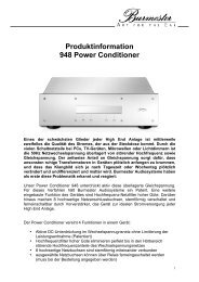
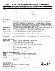
<strong>Mix</strong> <strong>Rack</strong> Front Panel<br />
ECx Port<br />
The ECx port lets you connect a laptop, tablet, or similar control<br />
device to the <strong>Mix</strong> <strong>Rack</strong>. (This port does not support networking<br />
or any communication other than ECx.) See the ECx<br />
Ethernet Option <strong>Guide</strong> for more information.<br />
USB Ports<br />
The USB ports on the front panel of the <strong>Mix</strong> <strong>Rack</strong> are USB 2.0<br />
ports, letting you connect iLoks, USB key disks and other USB<br />
devices. (An additional, secure USB port is located inside the<br />
<strong>Mix</strong> <strong>Rack</strong> chassis.)<br />
Power Switch<br />
The Power switch applies power to the <strong>Mix</strong> <strong>Rack</strong> and starts the<br />
VENUE system.<br />
Reset Buttons<br />
USB port<br />
(internal)<br />
ECx Ethernet port<br />
USB 2.0 ports<br />
Figure 1. <strong>Mix</strong> <strong>Rack</strong> front panel<br />
The Reset buttons, when pressed simultaneously and held, restart<br />
the VENUE system.<br />
See the Troubleshooting chapter of the D-Show or D-Show<br />
Profile guide for additional information.<br />
Power<br />
switch<br />
Word Clock I/O<br />
The Word Clock In and Word Clock Out ports let you integrate<br />
external digital devices with <strong>Mix</strong> <strong>Rack</strong>.<br />
Status LEDs<br />
Reset<br />
switches<br />
The Active and Sig LEDs indicate Word Clock status. Both the<br />
Active and Sig LEDs light green when the system is locked.<br />
Both LEDs blink red if there is a signal present but it cannot<br />
lock.<br />
FOH Link Connector<br />
Word Clock In/Out<br />
and Status LEDs<br />
FOH Link<br />
connector<br />
The FOH Link connector accepts the FOH Link cable that connects<br />
to the control surface (whether D-Show Profile, or<br />
D-Show Main). This cable provides all the data and audio connections<br />
between the control surface and <strong>Mix</strong> <strong>Rack</strong>.<br />
Chapter 1: Introduction 3
4<br />
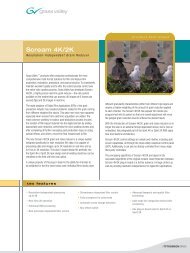
<strong>Mix</strong> <strong>Rack</strong> Back Panel<br />
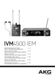
Figure 2. <strong>Mix</strong> <strong>Rack</strong> back panel, connectors, and I/O slots A–E<br />
Stage Input Section<br />
The Stage Input section provides 48 channels of audio input,<br />
arranged in three rows of 16 channels, to connect stage input<br />
sources. An analog multicore snake (not provided) is used to<br />
bring inputs from stage to the mix position.<br />
Stage Output Section<br />
The Stage Output Section provides 16 channels of stage output<br />
(expandable to 32) to connect to house/mains and stage<br />
monitors. <strong>Mix</strong> <strong>Rack</strong> can be expanded with other types of stage<br />
output (see “I/O Options” on page 2 for more information).<br />
CD-ROM Drive<br />
The built-in CD-ROM drive is for installing software updates,<br />
plug-ins, and other data.<br />
<strong>Mix</strong> <strong>Rack</strong> <strong>Guide</strong><br />
Stage Input<br />
section<br />
Stage Output<br />
section<br />
CD-ROM drive<br />
A<br />
B<br />
C<br />
D<br />
E<br />
FOH I/O<br />
The FOH I/O section includes connectors for audio (analog inserts,<br />
analog and digital 2-track inputs), synchronization<br />
(MIDI), and communication (Com mic input, with gain). For<br />
more information, see “FOH I/O Section” on page 5.<br />
Expansion Section<br />
FOH I/O<br />
section<br />
Expansion<br />
section<br />
These slots let you add an FWx or HDx Pro Tools Record/Playback<br />
Option (see “Record and Playback Options” on page 2 for<br />
more information).<br />
AC Power Connectors (2)<br />
AC power<br />
connectors and<br />
Status LEDs<br />
The AC Power connectors accept standard AC power cables,<br />
for powering each of the two internal <strong>Mix</strong> <strong>Rack</strong> power supply<br />
units. <strong>Mix</strong> <strong>Rack</strong> power supplies are auto-power selecting (100V<br />
to 240V, 50–60 Hz) and automatically work with a standard<br />
modular power cord when connected to an AC receptacle in<br />
any country.
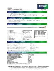
FOH I/O Section<br />
MIDI I/O<br />
MIDI I/O Ports<br />
These MIDI In and Out Ports provide 16 channels of MIDI input<br />
and 16 channels of MIDI output to the system. The MIDI<br />
I/O ports are used in sending and receiving Snapshot MIDI<br />
messages, and in receiving MIDI Time Code from external devices.<br />
Com Mic, Gain Control, and Phantom Power<br />
The Com Mic connector and controls allow connection of a<br />
mic, or a line level source. The Com Mic input is a female<br />
XLR/TRS connector that accepts XLR or TRS jacks. The Gain<br />
control operates in steps of 3 dB. Phantom power may be applied<br />
to the Com mic with the Mic Power switch.<br />
Monitor Outputs<br />
Com Mic Phantom Power<br />
Monitor<br />
Com Mic Gain<br />
Outputs<br />
Com Mic<br />
Input<br />
Figure 3. FOH I/O connectors on <strong>Mix</strong> <strong>Rack</strong><br />
2-Track Analog I/O<br />
Do not connect an intercom system directly to the Com<br />
input, as some intercom systems use a signalling voltage<br />
which can damage the FOH IO card.<br />
These Monitor Outputs are used for output to a near-field<br />
monitors or a cue mix system (not included). These are<br />
1/4-inch balanced TRS connectors.<br />
2-Track<br />
AES/EBU I/O<br />
2-Track Digital<br />
Format selector<br />
2-Track<br />
S/PDIF I/O<br />
2-Track Analog Inputs and Outputs<br />
These 2-Track analog connections are used for input and output<br />
of analog audio material. These are balanced 1/4-inch TRS<br />
connectors.<br />
2-Track Digital Inputs and Outputs<br />
These 2-Track digital connections are used for input and output<br />
of digital audio material. Stereo AES/EBU or S/PDIF I/O<br />
connectors are selectable with the AES–SPDIF switch. These<br />
connectors support 24-bit, 48 kHz digital signals. Input signals<br />
with other sample rates are sample-rate converted to<br />
48 kHz.<br />
Analog I/O (1–8)<br />
Analog I/O 1–8<br />
These 8 pairs of analog inputs and outputs are used for hardware<br />
inserts, or for input and output of program material from<br />
the mix position. These are balanced, 1/4-inch TRS connectors.<br />
Chapter 1: Introduction 5
6<br />
<strong>Mix</strong> <strong>Rack</strong> <strong>Guide</strong>
Chapter 2: Connecting the <strong>Mix</strong> <strong>Rack</strong><br />
Connecting D-Show to the <strong>Mix</strong> <strong>Rack</strong><br />
<strong>Mix</strong> <strong>Rack</strong> can be used with D-Show Profile, and D-Show Main/Sidecar control surfaces.<br />
To connect D-Show Profile and the <strong>Mix</strong> <strong>Rack</strong>:<br />
n Connect one end of the FOH Link cable to the FOH Link port on the back panel of the D-Show Profile control surface. Connect<br />
the other end of the FOH Link cable to the FOH Link port on the front panel <strong>Mix</strong> <strong>Rack</strong>. On each end, be sure to align the notch<br />
in the connector housing with the slot in the plug, and to rotate the collar until the connector is fully latched.<br />
Figure 4. FOH Link connection between D-Show Profile (left) and <strong>Mix</strong> <strong>Rack</strong> (right)<br />
To connect the D-Show Main Unit and the <strong>Mix</strong> <strong>Rack</strong>:<br />
n Connect one end of the FOH Link cable to the FOH Link port on the back panel of the Main Unit. Connect the other end of<br />
the FOH Link cable to the FOH Link port on the front panel <strong>Mix</strong> <strong>Rack</strong>. On each end, be sure to align the notch in the connector<br />
housing with the slot in the plug, and to rotate the collar until the connector is fully latched.<br />
Light Light<br />
I O<br />
FOH Link<br />
To <strong>Rack</strong> VGA<br />
Footswitch<br />
USB<br />
2<br />
1<br />
Console Link Console Link<br />
Sidecar 4-6<br />
Sidecar 1-3<br />
Figure 5. FOH Link connection between D-Show Main Unit (left) and <strong>Mix</strong> <strong>Rack</strong> (right)<br />
Chapter 2: Connecting the <strong>Mix</strong> <strong>Rack</strong> 7
8<br />
Audio Connections<br />
<strong>Mix</strong> <strong>Rack</strong> provides 48 analog mic/line inputs, up to 32 analog line outputs, and a variety of analog and digital audio inputs and<br />
outputs. You can use an analog multicore snake cable (not included) to carry multiple stage inputs and outputs to and from the<br />
<strong>Mix</strong> <strong>Rack</strong>, or you can connect mics, instruments and other sources directly to <strong>Mix</strong> <strong>Rack</strong> Stage inputs, and connect <strong>Mix</strong> <strong>Rack</strong> Stage<br />
outputs directly to the inputs on your house/mains systems, monitor systems, or other.<br />
For outboard effects processors, communications, and similar needs, see “FOH I/O Section” on page 5.<br />
Stage I/O<br />
Use the following sections to identify where to connect stage and FOH I/O to <strong>Mix</strong> <strong>Rack</strong>.<br />
analog snake<br />
Stage<br />
Inputs<br />
Figure 6. <strong>Mix</strong> <strong>Rack</strong> audio connectors and I/O slots (A–E) for stage inputs and outputs<br />
Stage Inputs 1–48<br />
(Analog Mic/Line XLR Inputs)<br />
The Stage Input section provides 48 channels of analog<br />
mic/line inputs (XLR), to connect stage input sources. You can<br />
use a standard analog snake cable to run lines from the stage<br />
to the <strong>Mix</strong> <strong>Rack</strong> (analog snake cable not included). Then connect<br />
the snake to Stage inputs 1–48. (For instructions on applying<br />
phantom power and other settings, see the guide that<br />
came with your control surface.)<br />
<strong>Mix</strong> <strong>Rack</strong> <strong>Guide</strong><br />
1–16<br />
17–32<br />
33–48<br />
A<br />
B<br />
C<br />
D<br />
E<br />
Stage Outputs 1–16<br />
(Analog Line XLR Outputs)<br />
FOH I/O<br />
(see next)<br />
Stage Outputs<br />
1–16<br />
to<br />
house/<br />
mains,<br />
monitors<br />
zones<br />
The Stage Output Section provides up to 32 channels of stage<br />
output (XLR), to connect to house/mains, monitors, additional<br />
zones, or feeds to other devices.
Ancillary Connections<br />
(AC Power, Synchronization and Optional Connections)<br />
AC Power Connectors<br />
The AC Power connectors accept standard AC power cable, for<br />
powering each of the two (redundant) internal <strong>Mix</strong> <strong>Rack</strong><br />
power supply units. <strong>Mix</strong> <strong>Rack</strong> power supplies are auto-power<br />
selecting (100V to 240V, 50–60Hz) and automatically work<br />
with a standard modular power cord when connected to an<br />
AC receptacle in any country.<br />
ECx Port<br />
The ECx port lets you connect an RJ-45 Ethernet cable for remote<br />
control of the system from a laptop or tablet computer.<br />
USB Ports<br />
The USB ports on the front panel of the <strong>Mix</strong> <strong>Rack</strong> are USB 2.0<br />
ports, letting you connect iLoks, USB key disks and other USB<br />
devices. (An additional, secure USB port is located inside the<br />
<strong>Mix</strong> <strong>Rack</strong> chassis as well; use this internal port to connect and<br />
secure a pre-loaded iLok to always be available to that <strong>Mix</strong><br />
<strong>Rack</strong> system.)<br />
FOH Link Connector<br />
(See “Connecting D-Show to the <strong>Mix</strong> <strong>Rack</strong>” on page 7.)<br />
Word Clock I/O<br />
The Word Clock In and Word Clock Out ports let you integrate<br />
external digital devices with <strong>Mix</strong> <strong>Rack</strong>.<br />
Powering the System Up and Down<br />
Powering Up<br />
Faders move when power is turned on. Before powering up the<br />
system, make sure all fader paths are clear of obstructions.<br />
Power up the system in the following sequence:<br />
1 D-Show Profile, or D-Show Main/Sidecar(s) control surface<br />
2 <strong>Mix</strong> <strong>Rack</strong><br />
3 Any connected computers for recording/playback options<br />
4 Audio monitoring system<br />
Each power supply has a separate power switch.<br />
Powering Down<br />
Power down the system in the following sequence:<br />
1 Audio monitoring system<br />
2 Any connected computers for recording/playback options<br />
3 <strong>Mix</strong> <strong>Rack</strong><br />
4 D-Show Profile, or D-Show Main/Sidecar(s) control surface<br />
Restarting the System<br />
If at any time during setup or performance it becomes necessary<br />
to restart the system, you can restart the entire system or<br />
reset individual hardware devices.<br />
Configuring your System with a<br />
<strong>Mix</strong> <strong>Rack</strong><br />
When using a VENUE system with a <strong>Mix</strong> <strong>Rack</strong>, the following<br />
parameters will be different (or unavailable) than on systems<br />
that use the original D-Show Stage <strong>Rack</strong> and FOH <strong>Rack</strong> units.<br />
Maximum System Configuration<br />
.<br />
For more information on restarting D-Show and resetting<br />
system hardware, see the Troubleshooting chapter of the<br />
D-Show guide that came with your control surface (D-Show<br />
Profile <strong>Guide</strong>, or D-Show <strong>Guide</strong>).<br />
Maximum <strong>Mix</strong> <strong>Rack</strong> Configuration<br />
Parameter Max<br />
<strong>Mix</strong> Engines 3<br />
Input Channels 48<br />
FX Returns 16<br />
Graphic EQs 24<br />
How to Proceed<br />
To learn how the <strong>Mix</strong> <strong>Rack</strong> appears in D-Show software, see<br />
the What’s New in D-Show 2.7 guide.<br />
To learn how to operate the VENUE system, see the D-Show<br />
Profile <strong>Guide</strong> or D-Show <strong>Guide</strong> that came with your control<br />
surface.<br />
Chapter 2: Connecting the <strong>Mix</strong> <strong>Rack</strong> 9
10<br />
<strong>Mix</strong> <strong>Rack</strong> <strong>Guide</strong>
Chapter 3: Mechanical Specifications<br />
<strong>Mix</strong> <strong>Rack</strong> Mechanical Specifications<br />
<strong>Mix</strong> <strong>Rack</strong> Specifications (Maximum Configuration)<br />
Dimensions (H x W x D) 19.25 x 19 x 18 inches (489 x 483 x 458 mm)<br />
<strong>Rack</strong> Spaces 11 U<br />
Weight 100 lbs (45.4 kg)<br />
Power Requirements AC 100–240V, 50–60 Hz, 360 W<br />
Word Clock In/Out Connectors BNC female (2)<br />
USB Ports (3, including internal)) USB 2.0<br />
FOH Link Connector MIL connector<br />
Max FOH Link Cable Length 11 ft. (3.35 m)<br />
Environmental<br />
Parameter Specification Limit Units Condition/Comment<br />
Storage Temperature 0 to +140 deg F –18 to +60 deg C<br />
Operating Temperature +40 to +115 deg F +4 to +40 deg C<br />
Storage humidity range 5 to 95 % Non-condensing<br />
Operating humidity range 20 to 80 % Non-condensing<br />
Chapter 3: Mechanical Specifications 11
12<br />
<strong>Mix</strong> <strong>Rack</strong> <strong>Guide</strong>
Chapter 4: Audio Specifications<br />
<strong>Mix</strong> <strong>Rack</strong> General Audio Specifications<br />
Audio, general<br />
Parameter Specification Limit Units Condition/Comment<br />
Internal Sample<br />
Rate<br />
External Sample<br />
Rate<br />
Processing Delay<br />
(latency)<br />
Internal Processing<br />
Frequency<br />
Response<br />
All measurements at Fs=48 kHz with 150 Ohm source impedance and 600 Ohm load impedance, unless otherwise specified.<br />
0 dBU = 0.775Vrms.<br />
48 kHz<br />
48 +/– 10 ppm (word clock input) kHz<br />
Less than 2.3 max ms 48 channels, stage input through L–R bus to<br />
stage output<br />
up to 48-bit, fixed point 288 dB internal dynamic range<br />
+/– 0.2 dB 20 Hz – 20 kHz BW, relative to 1 kHz<br />
Dynamic Range 110 min dB Analog stage input to analog stage output,<br />
re +24 dBu, A-weighted, 20 Hz – 20 kHz BW<br />
Crosstalk –100 max dB Adjacent Stage inputs to L–R bus, @ 1 kHz<br />
Residual Output<br />
Noise<br />
Maximum Voltage<br />
Gain<br />
–90 max dBu 20 Hz – 20 kHz BW<br />
84 dB Stage input to L–R bus, channel & L–R<br />
faders @ max<br />
Chapter 4: Audio Specifications 13
14<br />
Stage Inputs and Outputs<br />
Stage Inputs<br />
AI16 Analog Mic/Line Inputs<br />
Parameter Specifications Limit Units Condition/ Comment<br />
Type Balanced, XLR3-Female<br />
Gain +10 to +60 dB 6 dB analog steps with 0.1 dB<br />
digital increments and crossfade<br />
at analog relay switch point<br />
Max Input Level +32 dBu Pad ON<br />
Pad 20 dB<br />
Input Impedance, pad OFF 5.5k Ohm Each leg to ground<br />
Input Impedance, pad ON 3.8k Ohm Each leg to ground<br />
Phantom Power +48 VDC 10 mA max per channel<br />
EIN –126 max dBu Max gain, 150 ohm source,<br />
20 Hz–20 kHz BW, unweighted<br />
THD + N 0.003 % Minimum gain, pad OFF, –1 dBFS<br />
output, 20 Hz–20 kHz BW<br />
A/D Converter Latency 0.25 ms Fs=48kHz<br />
Stage Outputs<br />
AO16 Analog Line Outputs<br />
Parameter Specifications Limit Units Condition/ Comment<br />
Type Balanced, XLR3-Male<br />
Impedance 50 Ohm Each leg to ground<br />
Maximum Output Level +24 max dBu<br />
D/A Converter Latency 0.58 ms Fs=48kHz<br />
<strong>Mix</strong> <strong>Rack</strong> <strong>Guide</strong>
FOH Inputs and Outputs<br />
FOH Input<br />
Analog Line Inputs 1–8; 2–Track Analog Inputs<br />
Parameter Specification Limit Units Condition/Comment<br />
Type Balanced, 1/4-inch TRS<br />
Female<br />
Maximum Input Level +24 max dBu<br />
Input Impedance 10k Ohms<br />
THD+N 0.003 max % –1 dBFS output, 20 Hz<br />
to 20 kHz BW<br />
2–Track AES Input<br />
Parameter Specification Limit Units Condition/Comment<br />
Type XLR3-F<br />
Format AES/EBU<br />
Termination 110 Ohm<br />
Word Length 24 bit<br />
Sample Rate 48 kHz<br />
Sample Rate Conversion<br />
(SRC)<br />
2–Track S/PDIF Input<br />
32 to 96 kHz Always active<br />
Parameter Specification Limit Units Condition/Comment<br />
Type Unbalanced, co-axial<br />
(RCA)<br />
Format S/PDIF (IEC-60958<br />
Type II)<br />
Termination 75 Ohm<br />
Word Length 24 bit<br />
Sample Rate 48 nom kHz<br />
Sample Rate Conversion<br />
(SRC)<br />
32 to 96 kHz Always active<br />
Chapter 4: Audio Specifications 15
16<br />
Com Input (XLR/TRS)<br />
Parameter Specification Limit Units Condition/Comment<br />
Type Neutrik combi XLR/TRS<br />
Sensitivity –2 to –32 dBu Equals 0 dBFS. Switchable<br />
in 6 gain steps<br />
Phantom Power +15 VDC 6mA (switchable on <strong>Mix</strong><br />
<strong>Rack</strong> back panel)<br />
Input Impedance 20k Ohms<br />
Talkback Mic Input (XLR)<br />
Parameter Specification Limit Units Condition/Comment<br />
Type XLR3-F<br />
Sensitivity –20 dBu fixed<br />
Phantom Power +15 VDC 6mA (always on)<br />
Input Impedance 20k Ohms<br />
<strong>Mix</strong> <strong>Rack</strong> <strong>Guide</strong>
FOH Output<br />
Analog Line Outputs 1–8; 2–Track Analog Outputs; Monitor L/R<br />
Parameter Specification Limit Units Condition/Comment<br />
Type Balanced, 1/4-inch TRS<br />
Female<br />
Maximum Output Level +24 max dBu<br />
Output Impedance 50 Ohm<br />
2–Track AES Output<br />
Parameter Specification Limit Units Condition/Comment<br />
Type XLR3-M<br />
Format AES/EBU<br />
Word Length 24 bit<br />
Sample Rate 48 kHz<br />
Sample Rate Conversion<br />
(SRC)<br />
None<br />
Dithering None<br />
Channel Status Info Pro, Audio 48K, No<br />
Emphasis<br />
Max Cable Length 100 meter Without equalization,<br />
110 ohm cable<br />
Chapter 4: Audio Specifications 17
18<br />
2–Track S/PDIF Output<br />
Parameter Specification Limit Units Condition/Comment<br />
Type Unbalanced, co-axial<br />
(RCA)<br />
Format S/PDIF (IEC-60958<br />
Type II)<br />
Output Impedance 75 Ohm<br />
Word Length 24 bit<br />
Sample Rate 48 kHz<br />
Sample Rate Conversion<br />
(SRC)<br />
Synchronization and Control I/O<br />
<strong>Mix</strong> <strong>Rack</strong> <strong>Guide</strong><br />
None<br />
Dithering No<br />
Channel Status Info Consumer, Audio, 48K,<br />
Non-copy, 2-Channel,<br />
General Category, Level<br />
2 Clock<br />
Headphone Output<br />
Parameter Specification Limit Units Condition/Comment<br />
Type Unbalanced, 1/4-inch<br />
TRS Female<br />
Output Impedance 50 Ohm<br />
Located on console<br />
Max RMS Power Output 20 mW at +21 dBu with 32 Ohm<br />
headphones<br />
130 mW at +21 dBu with 600<br />
Ohm headphones<br />
Ancillary Connector Count Type<br />
MIDI In 5-Pin DIN F 1<br />
MIDI Out 5-Pin DIN F 1<br />
Word Clock In BNC-F 1<br />
Word Clock Out BNC-F 1<br />
FOH Link Multi-Pin 1 55-pin<br />
Ethernet (ECx) RJ-45 1 100BaseT