
You also want an ePaper? Increase the reach of your titles
YUMPU automatically turns print PDFs into web optimized ePapers that Google loves.
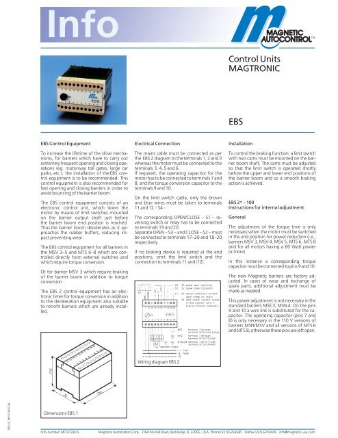
<strong>Control</strong> <strong>Units</strong><br />
<strong>MAGTRONIC</strong><br />
<strong>EBS</strong><br />
<strong>EBS</strong> <strong>Control</strong> Equipment<br />
To increase the lifetime of the drive mechanisms,<br />
for barriers which have to carry out<br />
extremely frequent opening and closing operations<br />
(eg. motorway toll gates, large car<br />
parks, etc.), the installation of the <strong>EBS</strong> control<br />
equipment is to be recommended. This<br />
control equipment is also recommended for<br />
fast opening and closing barriers in order to<br />
avoid bouncing of the barrier boom.<br />
The <strong>EBS</strong> control equipment consists of an<br />
electronic control unit, which slows the<br />
motor by means of limit switches mounted<br />
on the barrier output shaft just before<br />
the barrier boom end position is reached.<br />
Thus the barrier boom decelerates as it approaches<br />
the rubber buffers, reducing impact<br />
preventing wear.<br />
The <strong>EBS</strong> control equipment for all barriers in<br />
the MSV 3–5 and MTS 6–8 which are controlled<br />
directly from external switches and<br />
which require torque conversion.<br />
Or for barrier MSV 3 which require braking<br />
of the barrier boom in addition to torque<br />
conversion.<br />
The <strong>EBS</strong> 2 control equipment has an electronic<br />
timer for torque conversion in addition<br />
to the deceleration equipment also suitable<br />
to retrofit barriers which are already installed.<br />
Electrical Connection<br />
The mains cable must be connected as per<br />
the <strong>EBS</strong> 2 diagram to the terminals 1, 2 and 3<br />
whereas the motor must be connected to the<br />
terminals 3, 4, 5 and 6.<br />
If required, the operating capacitor for the<br />
motor has to be connected to terminals 7 and<br />
8, and the torque conversion capacitor to the<br />
terminals 9 and 10.<br />
On the limit switch cable, only the brown<br />
and blue wires must be taken to terminals<br />
11 and 12 – S4 -.<br />
The corresponding OPEN/CLOSE – S1 – reversing<br />
switch or relay has to be connected<br />
to terminals 19 and 20.<br />
Separate OPEN – S3 – and CLOSE – S2 – must<br />
be connected to terminals 17–20 and 18–20<br />
respectively.<br />
If no braking device is required at the end<br />
positions, omit the limit switch and the<br />
connection to terminals 11 and (12).<br />
Installation<br />
To control the braking function, a limit switch<br />
with two cams must be mounted on the barrier<br />
boom shaft. The cams must be adjusted<br />
so that the limit switch is operated shortly<br />
before the upper and lower end positions of<br />
the barrier boom and so a smooth braking<br />
action is achieved.<br />
<strong>EBS</strong> 2* – 100<br />
Instructions for internal adjustment<br />
General<br />
The adjustment of the torque time is only<br />
necessary when the motor must be switched<br />
in the end position for power reduction (i.e.,<br />
barriers MSV 3, MSV 4, MSV 5, MTS 6, MTS 8<br />
and for all motors having a 60 Watt power<br />
or more).<br />
In this instance a corresponding torque<br />
capacitor must be connected to pins 9 and 10.<br />
The new Magnetic barriers are factory adjusted.<br />
In cases of wear and exchange of<br />
spare parts, additional adjustment must be<br />
made as needed.<br />
This power adjustment is not necessary in the<br />
standard barriers MSE 3, MSN 4. On the pins<br />
9 and 10 a wire link is substituted for the capacitor.<br />
The operating capacitor (pins 7 and<br />
8) is only necessary in the 110 V versions of<br />
barriers MSN/MSV and all versions of MTS 6<br />
and MTS 8, otherwise these pins are left open.<br />
Wiring diagram <strong>EBS</strong> 2<br />
580 US, MF5150/02.04<br />
Dimensions <strong>EBS</strong> 1<br />
Info-number: MF 5150/US<br />
Magnetic Automation Corp. 3160 Murrell Road, Rockledge, FL 32955, USA Phone (321) 6358585 Telefax (321) 6359449 info@magnetic-usa.com
Setting of operation time<br />
(Torque reduction without braking)<br />
No limit switch should be connected to pins<br />
11 and 12 in this function.<br />
The unit should be powered ON with the<br />
boom connected during this operation (allow<br />
15 minutes warm up time):<br />
1. Remove terminal strip containing pins 11–<br />
20. Note the right potentiometer and adjust<br />
the performance time (picture 4). In<br />
accordance with the operation time (i.e.,<br />
MSV 3R/L-*** = 1.6 seconds or MSV 4R/<br />
L-*** = 4.0 seconds):<br />
Minimum (counter clockwise):<br />
approx. 2.5 seconds<br />
Maximum (clockwise):<br />
approx. 15 seconds<br />
The switching time should be approximately<br />
2–3 seconds longer than the effective<br />
operation time of the barrier arm.<br />
2. Re-mount the terminal.<br />
Adjustment of operation time<br />
(Torque reduction with brake function)<br />
Pins 11 and 12 must be mounted with a limit<br />
switch to achieve this function. The double<br />
cam adjustment should initially be set up for<br />
tripping the limit switch prior to opening and<br />
closing.<br />
1. Remove the terminal strip with pins 11–20<br />
and adjust both potentiometers in the<br />
maximum clockwise position.<br />
2. Re-mount the terminal strip.<br />
Positioning the limit switch cam settings<br />
In order to achieve an optimal braking function,<br />
the limit switch cam settings must be<br />
positioned while the motor is warm (and<br />
taking into consideration the velocity and<br />
weight of the barrier boom).<br />
a) closed position: between 15 and 30 °<br />
b) open position: between 75 and 80 °<br />
Note: The above is for 90 ° operation. Minor<br />
adjustments will assist in eliminating „bounce“<br />
of the barrier boom.<br />
If the adjustment is made correctly, a clear<br />
“clicking“ sound of the relay can be heard.<br />
This should occur approximately two seconds<br />
after the gate reaches its open or closed position.<br />
<strong>Control</strong> can also be made by use of a<br />
voltmeter (measurement 0–300 V AC on the<br />
pins 9 and 10 is also possible).<br />
Picture 4 Picture 5<br />
Subject to technical modifications.<br />
Magnetic Automation Corp. 3160 Murrell Road, Rockledge, FL 32955, USA Phone (321) 6358585 Telefax (321) 6359449 info@magnetic-usa.com