

Data Sheet - Freescale Semiconductor
Data Sheet - Freescale Semiconductor
Data Sheet - Freescale Semiconductor

Create successful ePaper yourself
Turn your PDF publications into a flip-book with our unique Google optimized e-Paper software.
General<br />
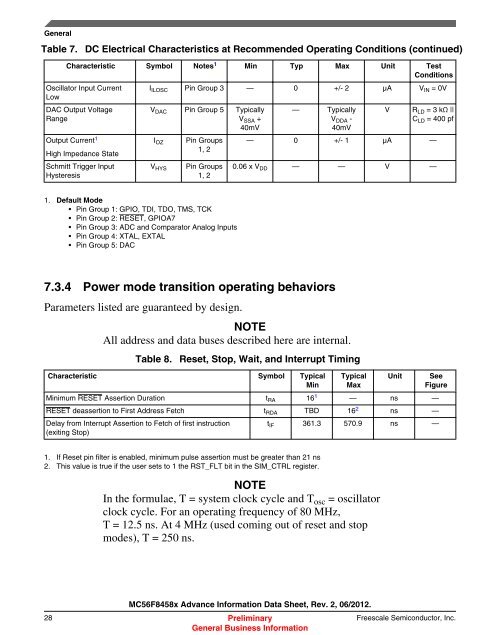
Table 7. DC Electrical Characteristics at Recommended Operating Conditions (continued)<br />
Characteristic Symbol Notes 1 Min Typ Max Unit Test<br />
Conditions<br />
Oscillator Input Current<br />
Low<br />
DAC Output Voltage<br />
Range<br />
Output Current 1<br />
High Impedance State<br />
Schmitt Trigger Input<br />
Hysteresis<br />
I ILOSC Pin Group 3 — 0 +/- 2 µA V IN = 0V<br />
V DAC Pin Group 5 Typically<br />
V SSA +<br />
40mV<br />
I OZ<br />
V HYS<br />
Pin Groups<br />
1, 2<br />
Pin Groups<br />
1, 2<br />
1. Default Mode<br />
• Pin Group 1: GPIO, TDI, TDO, TMS, TCK<br />
• Pin Group 2: RESET, GPIOA7<br />
• Pin Group 3: ADC and Comparator Analog Inputs<br />
• Pin Group 4: XTAL, EXTAL<br />
• Pin Group 5: DAC<br />
— Typically<br />
V DDA -<br />
40mV<br />
V R LD = 3 kΩ ||<br />
C LD = 400 pf<br />
— 0 +/- 1 µA —<br />
0.06 x V DD — — V —<br />
7.3.4 Power mode transition operating behaviors<br />
Parameters listed are guaranteed by design.<br />
NOTE<br />
All address and data buses described here are internal.<br />
Table 8. Reset, Stop, Wait, and Interrupt Timing<br />
Characteristic Symbol Typical<br />
Min<br />
Typical<br />
Max<br />
Unit See<br />
Figure<br />
Minimum RESET Assertion Duration t RA 16 1 — ns —<br />
RESET deassertion to First Address Fetch t RDA TBD 16 2 ns —<br />
Delay from Interrupt Assertion to Fetch of first instruction<br />
(exiting Stop)<br />
1. If Reset pin filter is enabled, minimum pulse assertion must be greater than 21 ns<br />
2. This value is true if the user sets to 1 the RST_FLT bit in the SIM_CTRL register.<br />
t IF 361.3 570.9 ns —<br />
NOTE<br />
In the formulae, T = system clock cycle and T osc = oscillator<br />
clock cycle. For an operating frequency of 80 MHz,<br />
T = 12.5 ns. At 4 MHz (used coming out of reset and stop<br />
modes), T = 250 ns.<br />
MC56F8458x Advance Information <strong>Data</strong> <strong>Sheet</strong>, Rev. 2, 06/2012.<br />
28 Preliminary <strong>Freescale</strong> <strong>Semiconductor</strong>, Inc.<br />
General Business Information


