DIPLOMAT LOGIC Manual - Sc.trapeza.ru
DIPLOMAT LOGIC Manual - Sc.trapeza.ru
DIPLOMAT LOGIC Manual - Sc.trapeza.ru

Create successful ePaper yourself
Turn your PDF publications into a flip-book with our unique Google optimized e-Paper software.
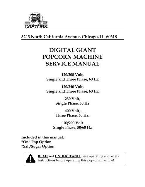
3243 North California Avenue, Chicago, IL 60618<br />
DIGITAL GIANT<br />
POPCORN MACHINE<br />
SERVICE MANUAL<br />
Included in this manual:<br />
*One Pop Option<br />
*Salt/Sugar Option<br />
120/208 Volt,<br />
Single and Three Phase, 60 Hz<br />
120/240 Volt,<br />
Single and Three Phase, 60 Hz<br />
230 Volt,<br />
Single Phase, 50 Hz<br />
400 Volt,<br />
Three Phase, 50 Hz.<br />
100/200 Volt<br />
Single Phase, 50/60 Hz<br />
READ and UNDERSTAND these operating and safety<br />
inst<strong>ru</strong>ctions before operating this popcorn machine!
TABLE OF CONTENTS<br />
EG20/32/48/60-M-A/E-S<br />
I. Safety Alert Symbol . . . . . . . . . . . . . . . . . . . . . . . . . . . . . . . . . . . . . . . . . 3<br />
II. Safety First . . . . . . . . . . . . . . . . . . . . . . . . . . . . . . . . . . . . . . . . . . . . . . . . . 3<br />
III. Introduction . . . . . . . . . . . . . . . . . . . . . . . . . . . . . . . . . . . . . . . . . . . . . . . . 3<br />
IV. Specifications . . . . . . . . . . . . . . . . . . . . . . . . . . . . . . . . . . . . . . . . . . . . . . . 5<br />
A. Electric Specifications<br />
B. Size Specifications<br />
V. Purpose of <strong>Manual</strong>. . . . . . . . . . . . . . . . . . . . . . . . . . . . . . . . . . . . . . . . . . . 5<br />
VI. Installation Inst<strong>ru</strong>ctions. . . . . . . . . . . . . . . . . . . . . . . . . . . . . . . . . . . . . . . 6<br />
A. Location<br />
B. Power Supply<br />
C. Connecting Machine to Power Supply<br />
D. OEM Option Pedestals. . . . . . . . . . . . . . . . . . . . . . . . . . . . . . . . . . 7<br />
E. Pump Installation & Timer Adjustment for Salt/Sugar Machines<br />
VII. Service Inst<strong>ru</strong>ctions . . . . . . . . . . . . . . . . . . . . . . . . . . . . . . . . . . . . . . . . . . 8<br />
A. Parts<br />
B. Kettle Temperature Control<br />
1. Temperature Control<br />
2. Digital Temperature Control Adjustment . . . . . . . . . . . . . . 9<br />
3. Checking Temperature Control . . . . . . . . . . . . . . . . . . . . . . . 10<br />
4. Salt Timer Adjustment<br />
5. Salt/Sugar With One Pop Adjustment . . . . . . . . . . . . . . . . . 11<br />
C. Kettle Removal<br />
D. Kettle Installation . . . . . . . . . . . . . . . . . . . . . . . . . . . . . . . . . . . . . . 12<br />
E. Kettle Spring Adjustment . . . . . . . . . . . . . . . . . . . . . . . . . . . . . . . 12<br />
VIII. Troubleshooting . . . . . . . . . . . . . . . . . . . . . . . . . . . . . . . . . . . . . . . . . . . . . 13<br />
Last printed 9/10/2007 1:56:00 PM 2 BEGIN SERIAL NO: 00035540
I. SAFETY ALERT SYMBOL<br />
EG20/32/48/60-M-A/E-S<br />
The symbol shown below is used to call your attention to inst<strong>ru</strong>ctions concerning your<br />
personal safety and the safety of others. Watch for this symbol. It points out important<br />
safety precautions and procedures. It means "ATTENTION! Become Alert! Your<br />
personal safety is involved!" Read the message that follows and be alert to the risk of<br />
personal injury or death.<br />
II. SAFETY FIRST<br />
III. INTRODUCTION<br />
The information in this manual is essential for the safe installation and<br />
service of your Cretors popcorn machine. The manual must be read and<br />
understood before installing, or maintaining equipment, or equivalent<br />
training must be provided.<br />
"The employer must inst<strong>ru</strong>ct each employee in the recognition and<br />
avoidance of unsafe conditions, regulations applicable to his work<br />
environment to control or eliminate any hazards or other exposure to<br />
illness or injury". Ref.: 29 CFR 1926.20 (b)(4)(a)(2)<br />
It is understood that safety <strong>ru</strong>les within individual companies vary. If a<br />
conflict exists between the safety procedures contained in this manual and<br />
the <strong>ru</strong>les of a using company, the more stringent <strong>ru</strong>le should take<br />
precedence.<br />
This manual is filled with time-saving and money-saving information regarding your<br />
Cretors popcorn machine. There is nothing, however, more important than the safety<br />
aids and warnings that are found throughout this document. The Safety Alert Symbol is<br />
used to identify topics of primary safety concern wherever they appear. A separate<br />
section has been included which deals exclusively with operation and accident<br />
prevention.<br />
If, after reviewing this manual, anything is unclear or technical problems are<br />
encountered, contact the distributor from whom you purchased your machine. For<br />
assistance and if there are any additional questions, feel free to contact our Customer<br />
Service Department at the address and/or phone number listed on the last page of this<br />
manual. Always have the model and serial number of your machine available to assist<br />
in obtaining the correct information.<br />
Last printed 9/10/2007 1:56:00 PM 3 BEGIN SERIAL NO: 00035540
CONFIGURATOR PAGE<br />
EG20/32/48/60-M-A/E-S<br />
Last printed 9/10/2007 1:56:00 PM 4 BEGIN SERIAL NO: 00035540
IV. SPECIFICATIONS<br />
Giant Models: EG20, EG32, EG48, EG60<br />
EG20/32/48/60-M-A/E-S<br />
A. Electrical Specifications:<br />
Giant Models are available in the following electrical configurations:<br />
100/200 Volt, Single Phase, 50 or 60 Hz<br />
120/208 Volt, 120/240 Volt, Single and Three Phase, 60 Hz<br />
230 Volt, 400 Volts, Single and Three Phase, 50 Hz<br />
B. Size Specifications:<br />
MODEL EG20 GIANT 20 OZ. ELECTRIC WITH PUMP<br />
Capacity: 20 oz. All-Steel Kettle, 400 one-ounce servings per hour.<br />
Wattage: 2950 watts<br />
Dimensions: 10-5/8”D x 10-1/2"W x 27-1/2" H - - - - 27 cm D x 26 cm W x 70 cm H<br />
Net Weight: 63 lbs. (28.6 kg)<br />
MODEL EG32 GIANT 32 OZ. ELECTRIC WITH PUMP<br />
Capacity: 32 oz. All-Steel Kettle, 640 one-ounce servings per hour<br />
Wattage: 4500 watts<br />
Dimensions: 10-5/8"D x 10-1/2"W x 31-3/4" H - - - - 27 cm D x 26 cm W x 81 cm H<br />
Net Weight: 74 lbs. (33.6 kg)<br />
MODEL EG48 GIANT 48 OZ. ELECTRIC WITH PUMP<br />
Capacity: 48 oz. All-Steel Kettle, 960 one-ounce servings per hour<br />
Wattage: 6050 watts<br />
Dimensions: 10-5/8"D x 10-1/2"W x 31-3/4"H - - - - 27 cm D x 26 cm W x 81 cm H<br />
Net Weight: 74 lbs. (33.6 kg)<br />
MODEL EG60 GIANT 60 OZ. ELECTRIC WITH PUMP<br />
Capacity: 60 oz. Stainless- Steel Kettle, 1200 one-ounce servings per hour.<br />
Wattage: 6050 watts<br />
Dimensions: 10-5/8”D x 10-1/2"W x 31-3/2" H - - - - 27 cm D x 26 cm W x 81 cm H<br />
Net Weight: 74 lbs. (33.6 kg)<br />
V. PURPOSE OF MANUAL<br />
This inst<strong>ru</strong>ction manual is intended to familiarize owners with the servicing and safety<br />
procedures associated with your Cretors popcorn machine.<br />
This manual should be kept available to maintenance personnel.<br />
Last printed 9/10/2007 1:56:00 PM 5 BEGIN SERIAL NO: 00035540
VI. INSTALLATION INSTRUCTIONS<br />
A. Location<br />
EG20/32/48/60-M-A/E-S<br />
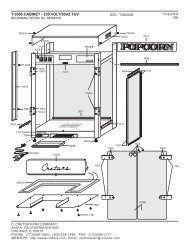
Choose a location for your Cretors popcorn machine that maximizes the ease of<br />
operation and maintenance procedures. Giant pedestal popcorn machines are<br />
designed to be installed on the customers counter or custom design cabinet.<br />
OEM option machines are supplied with components that permit them to be<br />
installed into a user’s cabinet and control the cornditioner, lights and exhaust in<br />
the cabinet (see details below). Be sure to check your local building and fire<br />
codes for location restrictions.<br />
B. Power Supply<br />
1. Check the nameplate to determine the required power supply.<br />
Connect your popcorn popper only to the correct power source. Failure<br />
to do so may result in personal injury or death and may damage your<br />
popper.<br />
2. C. Cretors and Company recommends dedicated circuits for the Giant<br />
model popcorn machine. The Giant model poppers require a dedicated<br />
circuit to avoid a voltage drop in the supply wiring. Check your local<br />
electrical codes regarding fuse or circuit breaker requirements.<br />
Make certain your popcorn machine is properly grounded. Failure to do<br />
so may result in damage to your equipment or present a shock hazard.<br />
C. Connecting Machine to Power Supply<br />
1. Make certain that power supply circuit breakers are in the off position.<br />
2. Locate the pedestal and bolt it down securely using the four bolt holes<br />
provided in the base of the pedestal.<br />
3. Power should be connected through one of the four large holes in the base<br />
of the pedestal.<br />
4. The electrical connection is made to the terminal strip, located to the right<br />
of the main switch.<br />
Last printed 9/10/2007 1:56:00 PM 6 BEGIN SERIAL NO: 00035540
D. OEM Option Pedestals<br />
EG20/32/48/60-M-A/E-S<br />
1. OEM OPTION machines are designed to supply power to the components<br />
normally associated with the popcorn machine. The primary features are a<br />
power cord with plug and a flexible armored cable to be connected to the<br />
user’s cornditioner assembly (15 amps). In addition, a terminal strip inside<br />
the pedestal provides a connection point to a switch (15 amps) that will<br />
control a user’s exhaust fan. Mounting studs for fluorescent ballast and a<br />
connection point for a light circuit are also supplied.<br />
2. EXHAUST FAN CONTROL machines may be equipped with a time delay<br />
fan control. This control provides a timer controlled switch that will turn<br />
on a customers exhaust fan when the kettle heat is turned on. When the<br />
heat is turned off the fan will continue to <strong>ru</strong>n for the time set on the timer in<br />
the pedestal. This circuit only provides a switch, it does not supply any<br />
power.<br />
All electrical connections outside the pedestal must be done in accordance<br />
with appropriate electrical codes and requirements.<br />
E. Pump Installation & Timer Adjustment for Salt/Sugar Machines<br />
Refer to the Service <strong>Manual</strong> included with the pump to be installed in the<br />
machine. When the Giant is equipped with the salt/sugar option, also see below<br />
for additional information.<br />
1. For the Salt/Sugar machine the pump timers are located in the machine<br />
not in the pump. One timer is marked “Salt”, the other “Sugar”. The<br />
timers are located in the pedestal.<br />
2. To adjust the pump time, use the following procedure:<br />
a. There are two adjustments on the timer. The small adjustment knob<br />
sets the maximum time the timer can <strong>ru</strong>n. Cretors will normally set<br />
this adjustment for 10s.<br />
10s = 0-10 seconds<br />
1m = 0-1 minute<br />
10m = 0-10 minutes<br />
b. The larger adjustment knob sets the actual <strong>ru</strong>n time (percentage of<br />
time allowed by the small adjustment knob). Example: If the<br />
maximum setting is set for 10s and the large knob is set at .9, the timer<br />
will <strong>ru</strong>n for 9 seconds. Adjust to taste for both timers.<br />
Last printed 9/10/2007 1:56:00 PM 7 BEGIN SERIAL NO: 00035540
VII. SERVICE INSTRUCTIONS<br />
A. Parts<br />
EG20/32/48/60-M-A/E-S<br />
In the case of improper operation, only a qualified person should perform<br />
the following diagnostic checks, and, if necessary, corresponding<br />
adjustments and repairs. Many of the following procedures present an<br />
electrical shock hazard and can cause serious injury or death.<br />
Perform work only on de-energized circuits. Failure to do so may lead to<br />
electrical shock resulting in personal injury or death.<br />
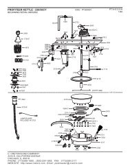
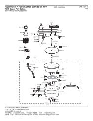
When ordering parts, refer to the parts diagram and/or wiring diagram included<br />
in this manual. Always supply the serial number, model number, and voltage of<br />
your popcorn machine.<br />
B. Kettle Temperature Control<br />
1. TEMPERATURE CONTROL OPERATION<br />
a. The temperature control is installed as a safety device to prevent<br />
overheating of the kettle if the machine should be left unattended<br />
momentarily while in operation. The kettle indicator light indicates<br />
the operation of the temperature control. If equipped, the indicator<br />
light is located on the switch plate. The indicator light will turn off<br />
10-20 seconds before the corn finishes popping and the kettle is<br />
dumped. If the indicator light turns off 30 seconds or more before the<br />
corn finishes popping, the temperature control is set too low and in<br />
need of adjustment. If the indicator light remains on after corn has<br />
finished popping the digital temperature control is set too high.<br />
b. Salt/Sugar Option: The indicator lights on the switchplate will reflect<br />
whether the Salt/Sugar switch is in the sugar mode or salt mode.<br />
When the Salt/Sugar switch is in the sugar mode, the digital<br />
temperature control alone controls the heat. When the switch is on<br />
the salt side the digital temperature control works the same way with<br />
one exception. When the digital temperature control opens, it<br />
activates a timer which allows the heat to stay on for extra time<br />
allowing the salted corn to pop.<br />
c. Digital Control does not have a thermostat but a thermocouple<br />
on the bottom of the pan.<br />
Last printed 9/10/2007 1:56:00 PM 8 BEGIN SERIAL NO: 00035540
EG20/32/48/60-M-A/E-S<br />
d. Cretors “CE” marked machines have been supplied with high limits for<br />
years to comply with the European Directives but these high limits are not<br />
resetting. Once they trip, they need to be replaced. This has not changed.<br />
Beginning in May of 2006, Cretors and Company has started implementing<br />
auto-resetting high limits into kettles and repair kettles as well. Again, the<br />
end customer/user will not see any difference in the operation of their<br />
machine but there is now an added level of safety so that the kettle<br />
temperature will not be able to exceed a safe level, even if the normal<br />
operating thermostat or temperature controller is adjusted to an unsafe level.<br />
This high limit is preset and is NOT to be adjusted for any reason. New<br />
wiring diagrams will be sent out with the new kettle assemblies for<br />
reference.<br />
2. DIGITAL TEMPERATURE CONTROL ADJUSTMENT<br />
CAUTION: If the corn has dried out, it may not finish popping at normal<br />
temperatures, and the light may appear to go out early. DO NOT<br />
ADJUST KETTLE TEMPERAUTRE BASED ON POOR QUALITY CORN.<br />
If set too high (over 500°F 260°C), the digital temperature control can<br />
cause a serious fire hazard.<br />
CAUTION: If the machine is equipped with the Salt/Sugar option, the<br />
temperature control should only be adjusted when the switch is in the<br />
sugar mode. When in salt mode, refer to “Salt timer adjustment” section.<br />
a. Press the “set” button.<br />
b. Use the up or down arrow buttons to adjust the temperature up or<br />
down.<br />
c. Press the “set” button again. (Note that for safety, this range is<br />
limited)<br />
d. The display will show the temperature go up or down.<br />
e. You should only raise or lower the temperature 5-10 ºF at a time.<br />
f. Set temperature so that the power to heat elements is cut off at the<br />
correct temperature.<br />
KETTLE SALTED CORN SUGAR CORN<br />
20-60 OZ. 400-410º F. (204-210º C) 375-385º F. (190-193º C)<br />
Last printed 9/10/2007 1:56:00 PM 9 BEGIN SERIAL NO: 00035540
3. CHECKING TEMPERATURE CONTROL<br />
EG20/32/48/60-M-A/E-S<br />
There are two ways of checking that the temperature control is set<br />
correctly.<br />
a. Place the pyrometer over the thermocouple position and turn the<br />
kettle heat on. Watch to see that the kettle heat shuts off at the correct<br />
temperature. Make adjustments as needed.<br />
b. The temperature control may be adjusted by observing the operation<br />
of the indicator light as described in the “Temperature Control<br />
Operation” section. Adjust the temperature control so that the kettle<br />
heat is turned off 10 to 20 seconds before the corn finishes popping<br />
and the kettle is dumped.<br />
Do not adjust the temperature so high that the pan smokes at the end of<br />
the popping cycle. If set too high (over 500°F or 260°C), the kettle can<br />
become a serious fire hazard.<br />
c. Observe two or three cycles of correct operation to be certain<br />
everything is working correctly. Your final setting should allow the<br />
indicator light to cycle off 10 to 20 seconds prior to dumping the kettle.<br />
4. SALT TIMER ADJUSTMENT (For machines supplied with Salt/Sugar<br />
Option only)<br />
When the Salt/Sugar switch is in the sugar mode, the thermostat alone<br />
controls the heat. When the switch is in the salt mode, the temperature<br />
control works the same way with the exception that when the temperature<br />
control opens, it activates a timer, which allows the heat to stay on for an<br />
extended period of time allowing the salted corn to pop. The salt timer is<br />
located in the pedestal of all Giants marked “Salt Timer”. In salt mode:<br />
a. If the indicator light turns off 30 seconds or more before the corn<br />
finishes popping, the timer is set too low and is in need of adjustment.<br />
b. There are two adjustments on the timer. The small adjustment knob<br />
sets the maximum time the timer can <strong>ru</strong>n. Cretors will normally set this<br />
adjustment for 1m.<br />
10s = 0-10 seconds<br />
1m = 0-1 minute<br />
10m = 0-10 minutes<br />
c. The larger adjustment knob sets the actual <strong>ru</strong>n time (percentage of time<br />
allowed by the small adjustment knob). Example: If the maximum<br />
setting is set for 1m and the large knob is set at .5, the timer will <strong>ru</strong>n for<br />
30 seconds. In this case, the heat will stay on 30 seconds after the<br />
temperature control opens.<br />
Last printed 9/10/2007 1:56:00 PM 10 BEGIN SERIAL NO: 00035540
5. SALT/SUGAR WITH ONE POP ADJUSTMENT<br />
a. If the Salt/Sugar switch is in the sugar position, use the “Digital<br />
Temperature Control Adjustment” section.<br />
EG20/32/48/60-M-A/E-S<br />
b. If the Salt/Sugar switch is in the salt position, the temperature is adjusted on<br />
the One Pop Timer/Relay.<br />
c. On the Relay there are dip switches very similar to the timer in our 7700-7900<br />
pumps.<br />
d. From the factory the dip switches 7 and 9 will be on. To turn the dip switches<br />
ON the dip switch needs to be pressed down to the number side opposite of<br />
the open side.<br />
C. Kettle Removal<br />
Switch #6 = 5 seconds<br />
#7 = 10 seconds<br />
#8 = 20 seconds<br />
#9 = 40 seconds<br />
Example: If you turn #7 and #9 on, the time delay will be 50 seconds.<br />
To remove the kettle assembly, perform the following operations:<br />
1. Unplug the popcorn machine from the power supply. Make sure the kettle<br />
is not hot.<br />
2. Remove the cover on the terminal box between the pan support legs.<br />
3. Disconnect the three power leads, observing the color of the wires. Correct<br />
color code is: Left to right, BLACK, RED, WHITE. (For 400V units BLUE,<br />
BROWN, WHITE on front terminal left to right, Black on back terminal.)<br />
4. Remove the two bolts on the side of the aluminum pan legs.<br />
Using proper lifting techniques, when removing the kettle by lifting it<br />
straight up.<br />
Last printed 9/10/2007 1:56:00 PM 11 BEGIN SERIAL NO: 00035540
EG20/32/48/60-M-A/E-S<br />
5. Turn the kettle upside down and remove the bolts that hold the dump<br />
handle and retainer and lift the retainer off the kettle.<br />
6. When removing nuts and spacers from the threaded studs on the bottom of<br />
the pan, do not wipe off the silver lubricant. Without this lubricant<br />
(NEVER SEEZ) the nuts may freeze on the studs and cause the studs to<br />
break when the nuts are turned in an attempt to remove them.<br />
D. Kettle Installation<br />
1. When re-assembling the kettle, be sure all nuts and bolts are tight. Check<br />
to make sure that all electrical connections are secure. A loose connection<br />
can heat up and burn off the wires.<br />
2. Set the kettle back in place and replace the two bolts in the pan legs.<br />
3. Locate the kettle so that the clutch dog lines up with the motor drive head,<br />
and tighten the two front bolts that hold the pan leg plate, then tip the<br />
kettle and tighten the other two bolts.<br />
4. Connect the three power leads, observing the color of the wires. Again,<br />
correct color code is left to right, BLACK, RED, WHITE. (For 400V units<br />
BLUE, BROWN, WHITE on front terminal left to right, Black on back<br />
terminal.)<br />
5. Replace the terminal box cover.<br />
6. Turn on the agitator motor and dump the kettle. If the drive shaft does not<br />
engage and dis-engages freely, readjust the kettle.<br />
E. Kettle Spring Adjustment<br />
The purpose of the kettle counter balance springs is to reduce the force required<br />
to dump the kettle. The spring collars are held in place by set screws that fit into<br />
holes drilled on the bottom of the cross shaft. The spring collars have five holes<br />
that the spring fits into. By turning the collar around, there are five different<br />
adjustment positions for spring tension adjustment.<br />
When correctly adjusted the springs will neutralize the weight of the kettle. To<br />
set the springs raise the kettle to a point where it is balanced. The long leg of the<br />
1902 spring should be just beginning to touch the bar on the bottom edge of the<br />
hinge casting and the 1903 spring will begin to move away from the bar. If the<br />
springs press against the bar too soon the kettle will seem lighter but the springs<br />
are fighting each other. This condition will shorten the life of the springs.<br />
An important part of this assembly are the two washers between the 1902 spring<br />
and the plate welded to the cross shaft. They act as both bearings and spacers;<br />
without them the spring may have a short life.<br />
Last printed 9/10/2007 1:56:00 PM 12 BEGIN SERIAL NO: 00035540
VIII. TROUBLESHOOTING<br />
PROBLEM POSSIBLE<br />
CAUSE<br />
Popping is Incorrect amount<br />
slow.<br />
of corn and oil is<br />
used.<br />
Kettle indicator<br />
light goes out<br />
more than 30<br />
seconds before the<br />
corn finishes<br />
popping.<br />
Indicator light<br />
stays on. Digital<br />
Control never<br />
reaches temp.<br />
Voltage may be<br />
low.<br />
One of the elements<br />
in a multi-element<br />
ACTION<br />
EG20/32/48/60-M-A/E-S<br />
Refer to the chart located in the<br />
Operations <strong>Manual</strong>.<br />
Temperature is set too low. (Refer to<br />
“Digital Temperature Control<br />
Adjustment”).<br />
If machine is equipped with<br />
salt/sugar option and popping in salt<br />
mode, timer may be set low. (Refer to<br />
the “Salt Time Adjustment” or the<br />
“Salt/Sugar One Pop Adjustment”<br />
sections.<br />
Check the voltage at the circuit<br />
breaker with the kettle heat on.<br />
Extension cords or inadequate wiring<br />
will provide full voltage, if no load is<br />
applied. Once the kettle heat and<br />
auxiliaries are turned on, the voltage<br />
may drop 5 to 10 volts.<br />
Use an ammeter to diagnose.<br />
pan may have failed. Check the amperage draw of the heating<br />
elements, by using a clamp-on ammeter.<br />
1. Remove the front cover by removing<br />
the screws that hold the front cover to the<br />
pedestal.<br />
2. Turn on the kettle heat.<br />
3. If machine has one-pop option shut off<br />
the oil switch and press the one-pop<br />
button.<br />
4. Place the ammeter around the lead to<br />
the popper kettle as listed. The following<br />
current draws are normal. 120/208-240V<br />
and 100/200V machines black or red<br />
230V machines-blue or brown 400V<br />
machines-black or brown.<br />
CAUTION: If the corn has dried out, it may not finish popping at normal<br />
temperatures, and the light may appear to go out early. DO NOT<br />
ADJUST KETTLE TEMPERATURE BASED ON POOR QUALITY CORN.<br />
Last printed 9/10/2007 1:56:00 PM 13 BEGIN SERIAL NO: 00035540
KETTLE<br />
SIZE<br />
EG20/32/48/60-M-A/E-S<br />
CAUTION: Do not adjust the temperature so high that the pan smokes at<br />
the end of the popping cycle. If set too high (over 500°F or 260oC), the<br />
kettle can become a serious fire hazard.<br />
AMPS @<br />
200V<br />
AMPS @<br />
208V<br />
AMPS @<br />
230V<br />
AMPS @<br />
240V<br />
20 oz. 12.5 13.0 10.8 11.2<br />
32 oz. 19.6 20.4 17.0 17.7<br />
48/60 oz. 26.8 28.1 23.4 24.4<br />
380V – Place the ammeter around the black or brown lead to the popper kettle<br />
KETTLE SIZE<br />
32 oz.<br />
48/60 oz.<br />
AMPS @ 380V Brown<br />
8<br />
11<br />
PROBLEM POSSIBLE CAUSE ACTION<br />
A low reading may indicate a problem in<br />
the kettle. One or more of the heat elements<br />
may not be functioning properly. If the<br />
element is not functioning, the possible<br />
causes are:<br />
1. The element has burned out.<br />
2. A lead wire has burned off<br />
one of the element terminals<br />
due to a loose connection.<br />
Continuity Test and Ohms Test<br />
Black<br />
9<br />
13.2<br />
In either case the kettle must be removed<br />
and the problem identified.<br />
1. Remove kettle. (See section Kettle<br />
Removal for inst<strong>ru</strong>ctions.)<br />
2. Check for short circuits inside the kettle.<br />
3. If wires must be replaced, be sure to use<br />
nickel wire supplied by Cretors<br />
Conventional copper or “stove wire will<br />
have limited life.<br />
4. Make a visual check for broken, loose,<br />
burned or heat damaged wires. If there are<br />
no obvious broken or loose wires shorting<br />
out on the kettle, the elements must be<br />
checked.<br />
5. Perform a continuity test on the<br />
elements. It is possible that one of the<br />
elements has burned through the<br />
insulation and the casing is shorting out<br />
directly to the kettle bottom.<br />
When checking Ohms, make sure that the meter probes are making good contact on the<br />
terminals. Remove the nickel buss bars that connect the electrical terminals on the heat<br />
elements.<br />
Using a multimeter, check each element between the following points:<br />
Last printed 9/10/2007 1:56:00 PM 14 BEGIN SERIAL NO: 00035540
EG20/32/48/60-M-A/E-S<br />
Terminal to terminal Ohm readings should match chart listed<br />
below.<br />
If Ohm readings are not close, replace.<br />
First terminal to element case Continuity to case from terminal indicates a<br />
grounded element; replace.<br />
No continuity – functioning properly.<br />
Second terminal to element case Continuity to case from terminal indicates a<br />
grounded element; replace.<br />
No continuity – functioning properly.<br />
Do not attempt electrical repairs on the power supply circuit unless you<br />
are qualified to do so. The electrical shock associated with line voltages<br />
can cause serious injury or death.<br />
The following procedures are performed with the power on. As with any<br />
electrical repairs, there is a shock hazard present.<br />
Elements Coil Relay<br />
(top to bottom)<br />
BAD<br />
GOOD<br />
200 Volts 100 Volts 200 Volts 0 Volts<br />
208 Volts 120 Volts 208 Volts 0 Volts<br />
230 Volts 230 Volts 230 Volts 0 Volts<br />
240 Volts 120 Volts 240 Volts 0 Volts<br />
400 Volts 230 Volts 230 Volts (same pole) 0 Volts (same pole)<br />
20 oz. - 208V elements 1983-D<br />
1447-D<br />
20 oz. – 240V elements 1983-C<br />
1447-C<br />
900 Watt – 48.1 Ω<br />
1800 Watt – 24.0 Ω<br />
2700 Watt - 16.0 Ω (total)<br />
900 Watt – 64.0 Ω<br />
1800 Watt – 32.0 Ω<br />
2700 Watt - 21.3 Ω (total)<br />
Last printed 9/10/2007 1:56:00 PM 15 BEGIN SERIAL NO: 00035540
32 oz. – 208V elements 1448-D<br />
1528-D<br />
1043-D<br />
32 oz. – 240V elements 1448-C<br />
1528-C<br />
1043-C<br />
48 oz & 60 oz.. – 208V elements 1010-D<br />
1808-D<br />
1447-D<br />
1043-D<br />
48 oz. & 60 oz. – 240V elements<br />
1010-C<br />
1080-C<br />
1447-C<br />
1043-C<br />
EG20/32/48/60-M-A/E-S<br />
750 Watt – 57.7 Ω<br />
1500 Watt – 28.8 Ω<br />
2000 Watt – 21.6 Ω<br />
4250 Watt - 10.7 Ω (total)<br />
750 Watt – 76.8 Ω<br />
1500 Watt – 33.4 Ω<br />
2000 Watt – 28.8 Ω<br />
4250 Watt - 13.6 Ω (total)<br />
750 Watt – 57.7 Ω<br />
1250 Watt – 34.7 Ω<br />
1800 Watt – 24.0 Ω<br />
2000 Watt – 21.6 Ω<br />
5800 Watt - 7.5 Ω (total)<br />
750 Watt – 76.8 Ω<br />
1250 Watt – 46.1Ω<br />
1800 Watt – 32.0Ω<br />
2000 Watt – 28.8Ω<br />
5800 Watt - 9.9 Ω (total)<br />
Replace failed heat elements with identical units available from your local dealer or from<br />
Cretors. Reassemble and reinstall kettle assembly onto the machine.<br />
Last printed 9/10/2007 1:56:00 PM 16 BEGIN SERIAL NO: 00035540
PROBLEM POSSIBLE CAUSE ACTION<br />
Kettle will not<br />
heat.<br />
Digital<br />
Temperature<br />
Control<br />
display shows<br />
EO<br />
The motor, light or<br />
any of the other<br />
components do not<br />
work.<br />
Problem is in the<br />
machine.<br />
If machine has the<br />
one-pop option.<br />
Thermocouple has<br />
bad connections.<br />
Thermocouple is<br />
bad. Should read 3-<br />
5 ohms if good.<br />
EG20/32/48/60-M-A/E-S<br />
Check power supply:<br />
1. Is it plugged in?<br />
2. Is the receptacle live?<br />
3. Is the machine plugged into the proper voltage?<br />
(Measure with voltmeter and compare to<br />
specification on nameplate of machine.)<br />
Check the relay/contactor. The Giant<br />
temperature control uses a relay/contactor to<br />
control the power to the popper pan heat<br />
elements. To check the relay/contactor, perform<br />
the following operations:<br />
1. To gain access to the relay/contactor, remove<br />
the front switchplate by removing the six screws<br />
on the sides of the switchplate.<br />
2. Using a voltmeter, check the power to the relay<br />
coil, that are the small terminals in the center.<br />
3. With the popper switch on, at room<br />
temperature, the temperature control should be<br />
calling for heat and providing power to the<br />
relay/contactor. If the coil reading is not 120<br />
volts. (230 volts on 230V and 400V, 50Hz<br />
machines) the problem is in the temperature<br />
control.<br />
4. If the coil reading is 120 volts, (230 volts on<br />
230V and 400V machines) check the voltage<br />
between the output terminal with wire #1 and the<br />
output terminal with wire #3 from the kettle<br />
support. If this does not have a reading of 208 or<br />
240 volts, the relay/contactor is not functioning<br />
and needs to be replaced.<br />
Use the same procedure as above. Then check the<br />
one-pop circuit.<br />
1. With the power OFF. Check the one-pop<br />
switch for continuity by pressing and holding it<br />
down. Remove wires (mark wires for proper reinstallation)<br />
from switch and press and hold.<br />
Using a multimeter, check for continuity from top<br />
to bottom of switch. If no continuity, replace<br />
switch.<br />
2. Check the input (com) and output (no) on<br />
timer/relay.<br />
Check all connections.<br />
Replace thermocouple.<br />
Last printed 9/10/2007 1:56:00 PM 17 BEGIN SERIAL NO: 00035540
EG20/32/48/60-M-A/E-S<br />
PROBLEM POSSIBLE CAUSE ACTION<br />
Corn Burns Agitator is not working. Check to be certain the<br />
stirrer blade is on the<br />
bottom of the pan and is<br />
stirring the corn.<br />
Check motor connections. Loose wire.<br />
The motor is bad. Replace.<br />
The correct amount of corn and oil See Operations <strong>Manual</strong> for<br />
were not used.<br />
correct amounts.<br />
Temperature is set too high. Adjust temperature.<br />
Kettle leaks<br />
oil at<br />
agitator.<br />
Pump will<br />
not heat.<br />
If the kettle is not cleaned on a regular<br />
basis the popping oil will build up and<br />
turn to carbon on the inside of the<br />
blade center. When this happens the<br />
clearance between the blade center<br />
and the pan center is reduced from<br />
1/8” (3mm). As this clearance is<br />
reduced, the oil will “wick” up the<br />
narrow space and <strong>ru</strong>n down the<br />
rotating shaft and it will appear that<br />
the kettle is leaking for 20 oz. kettles.<br />
When reassembling, lightly<br />
coat the clutch dog shaft<br />
with moly grease or a<br />
comparable high<br />
temperature lubricant.<br />
Pump switch is on. Check pump switch.<br />
Remove wires from switch<br />
(mark wires for proper reinstallation.)<br />
Using a<br />
multimeter, check for<br />
continuity from top to<br />
bottom of switch. If no<br />
continuity, replace switch.<br />
Last printed 9/10/2007 1:56:00 PM 18 BEGIN SERIAL NO: 00035540
EG20/32/48/60-M-A/E-S<br />
This manual is filled with time-saving and money-saving information regarding your<br />
Cretors popcorn popper. There is nothing, however, more important than the safety<br />
aids and warnings found throughout this document.<br />
If you have any questions, contact your local distributor and if there are any additional<br />
questions, feel free to contact the Customer Service Department at C. Cretors and<br />
Company.<br />
Additional copies of this manual can be obtained from C. Cretors and Company at the<br />
address listed below. Please provide model and serial number when requesting<br />
additional copies of this manual. There will be a nominal charge for additional copies.<br />
Cretors guarantees this machine to be free of defects in parts, materials and<br />
workmanship for two years. Please take this time to fill out the factory registration card<br />
and return it to the factory to activate your warranty. If you have any questions<br />
concerning the Cretors' warranty, please contact your local distributor or the Customer<br />
Service Department at C. Cretors and Company.<br />
C. CRETORS AND COMPANY<br />
3243 N. CALIFORNIA AVENUE<br />
CHICAGO, IL 60618<br />
PHONE (773) 588-1690, (800) 228-1885, FAX (773) 588-7141<br />
WEB SITE: http://www.cretors.com Email: postmaster@cretors.com<br />
Last printed 9/10/2007 1:56:00 PM 19 BEGIN SERIAL NO: 00035540