Digital Satellite Downlink Reception - American Forces Radio and ...
Digital Satellite Downlink Reception - American Forces Radio and ...
Digital Satellite Downlink Reception - American Forces Radio and ...
You also want an ePaper? Increase the reach of your titles
YUMPU automatically turns print PDFs into web optimized ePapers that Google loves.
Defense Media Center <strong>Satellite</strong> H<strong>and</strong>book V.3.26<br />
The low noise block down converter, the LNB, detects the signal relayed from the<br />
feed, converts it to an electrical current, amplifies it <strong>and</strong> down-converts or lowers<br />
its frequency. LNBs in both analog <strong>and</strong> digital systems down-convert the signal to<br />
a b<strong>and</strong> in the 950 to 1450 MHz range. The “down-converted” signal is<br />
subsequently relayed along cable to the indoor satellite receiver.<br />
Signals reaching the input of an LNB from a typical 8-foot C-b<strong>and</strong> dish have<br />
powers of less than 10 –14 watts/m 2 . Therefore, an LNB must contribute very little<br />
noise power or received satellite signals will be drowned out in the roar of<br />
amplifier internal thermal noise. This feat is made possible by advances in<br />
transistor technology. Without such progress, satellite broadcasting would not<br />
exist as we know it today.<br />
LNB Performance<br />
There are three specifications that affect the performance of the LNB <strong>and</strong> have a<br />
direct effect on the ability of a system to satisfactorily capture a satellite signal. In<br />
order of importance for digital reception is, the noise temperature, Local<br />
Oscillator stability (L.O.), <strong>and</strong> its gain expressed in dB. The noise temperature of<br />
the amplifier must be low enough to overcome the noise floor of the antenna to a<br />
minimum of 8dB above the signal to noise floor.<br />
Feedhorn Assembly<br />
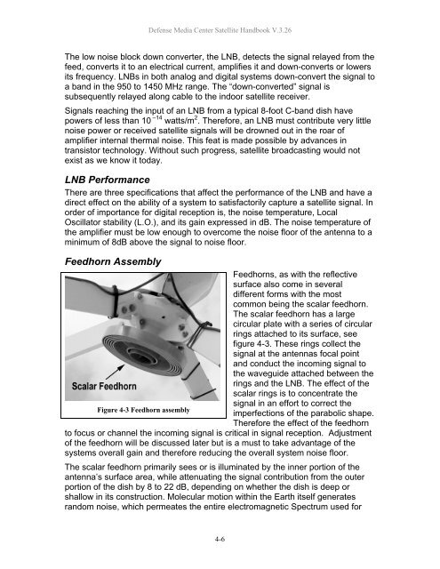
Feedhorns, as with the reflective<br />
surface also come in several<br />
different forms with the most<br />
common being the scalar feedhorn.<br />
The scalar feedhorn has a large<br />
circular plate with a series of circular<br />
rings attached to its surface, see<br />
figure 4-3. These rings collect the<br />
signal at the antennas focal point<br />
<strong>and</strong> conduct the incoming signal to<br />
the waveguide attached between the<br />
rings <strong>and</strong> the LNB. The effect of the<br />
scalar rings is to concentrate the<br />
signal in an effort to correct the<br />
Figure 4-3 Feedhorn assembly<br />
imperfections of the parabolic shape.<br />
Therefore the effect of the feedhorn<br />
to focus or channel the incoming signal is critical in signal reception. Adjustment<br />
of the feedhorn will be discussed later but is a must to take advantage of the<br />
systems overall gain <strong>and</strong> therefore reducing the overall system noise floor.<br />
The scalar feedhorn primarily sees or is illuminated by the inner portion of the<br />
antenna’s surface area, while attenuating the signal contribution from the outer<br />
portion of the dish by 8 to 22 dB, depending on whether the dish is deep or<br />
shallow in its construction. Molecular motion within the Earth itself generates<br />
r<strong>and</strong>om noise, which permeates the entire electromagnetic Spectrum used for<br />
4-6


