Digital Satellite Downlink Reception - American Forces Radio and ...
Digital Satellite Downlink Reception - American Forces Radio and ...
Digital Satellite Downlink Reception - American Forces Radio and ...

You also want an ePaper? Increase the reach of your titles
YUMPU automatically turns print PDFs into web optimized ePapers that Google loves.
Defense Media Center <strong>Satellite</strong> H<strong>and</strong>book V.3.26<br />
Chapter 4 : <strong>Digital</strong> <strong>Satellite</strong> <strong>Downlink</strong> <strong>Reception</strong><br />
The AFRTS signal is a digitally compressed MPEG signal <strong>and</strong> as with any digital<br />
signal there is perfect reception or nothing at all. Tuning to an MPEG<br />
compressed digital signal, however, is a little different from tuning to a st<strong>and</strong>ard<br />
analog signal. Weak signals appear to be r<strong>and</strong>om noise; the receiver will not<br />
display any picture at all until sufficient signal is reaching the antenna. Then,<br />
once the digital threshold of the receiver/decoder is exceeded, a perfect picture<br />
will appear on the TV screen. MPEG digital reception is like a light switch; it’s on<br />
or off. This is to say that a digital signal has two states, perfect (on) picture<br />
quality <strong>and</strong> reception or nothing at all (off). Furthermore, if the installer moves<br />
past the antenna’s peak performance position, the picture will “freeze frame” on<br />
the last picture in its buffer memory. The IRD will not receive any further video<br />
until the antenna is repositioned to receive a signal above minimum receiver<br />
threshold. Peaking the signal improves the overhead above threshold <strong>and</strong><br />
ensures a good picture under poor weather conditions.<br />
Typical <strong>Satellite</strong> TVRO Equipment Configuration<br />
The typical equipment arrangements used to receive AFRTS services are<br />
provided at Figure 3-2. Specific equipment requirements for receiving AFRTS<br />
services are provided in the section titled Qualification of <strong>Satellite</strong> Terminals or<br />
<strong>Digital</strong> <strong>Reception</strong>.<br />
General <strong>Satellite</strong> Concepts<br />
The concepts underlying satellite broadcasting are straightforward: signals<br />
beamed into space by an “uplink” dish are received by an orbiting satellite,<br />
electronically processed, re-broadcast or “down-linked” back to earth <strong>and</strong> then<br />
detected by a dish <strong>and</strong> associated electronics. A receiving station can be situated<br />
anywhere within the satellite’s “footprint” (see Chapter 3, satellite footprint maps).<br />
The overwhelming strength of satellite broadcasting lies in its ability to reach an<br />
unlimited number of sites regardless of their location without the need for any<br />
physical connections.<br />
Nearly all communication satellites designated for commercial use are positioned<br />
or “parked” in the “Clarke Belt”, also known as the “geostationary” arc. The<br />
Clarke belt lies in the equatorial plane 22,300 miles above the equator. This<br />
circle around the earth is unique because in this orbit the velocity of a spacecraft<br />
matches that of the surface of the earth below. Therefore each satellite appears<br />
to remain in a fixed orbital slot in the sky above. This allows a stationary dish to<br />
be permanently aimed towards a targeted geostationary satellite.<br />
A satellite receives the up-linked signal, lowers its frequency <strong>and</strong> re-broadcasts it<br />
to any chosen geographic area. <strong>Downlink</strong> transmit antennas can target over 40%<br />
of the earth’s surface with “global” beams, can broadcast to selected countries or<br />
continents via “zone” beams, or can pinpoint smaller areas with “spot” beams.<br />
Many domestic C-b<strong>and</strong> broadcast satellites direct one beam that blankets the<br />
continental U.S. <strong>and</strong> a second more localized one to the Hawaiian Isl<strong>and</strong>s. Ku-<br />
4-1
Defense Media Center <strong>Satellite</strong> H<strong>and</strong>book V.3.26<br />
b<strong>and</strong> satellites, operating in the higher frequency 12 GHz range, are configured<br />
for spot beams <strong>and</strong> require smaller antennas to receive their signals.<br />
The Receive Site<br />
At the receive site a dish reflects <strong>and</strong> concentrates as much of the very weak<br />
down-linked signal as possible to its focus where a feed channels the signals into<br />
the first electronic component, the low noise block converter (LNB). The signal is<br />
then cabled indoors to the satellite receiver <strong>and</strong> processed into a form that can<br />
be deciphered by a television, stereo or computer.<br />
<strong>Radio</strong> Waves <strong>and</strong> Communications<br />
The transmission of extremely low power microwaves, a form of radio waves,<br />
underlies the operation of radio, conventional television, satellite broadcasting<br />
<strong>and</strong> other man-made communication devices. They are one form of more general<br />
phenomena known as electromagnetic waves that travel at the speed of light,<br />
equal to 186,000 miles per second. At this rate, a signal travels from the uplink,<br />
to a satellite <strong>and</strong> back again to earth in about 4/10ths of a second.<br />
<strong>Radio</strong> Waves<br />
<strong>Radio</strong> waves are defined by their frequency, power <strong>and</strong> polarization. These<br />
parameters are briefly discussed below.<br />
Signal Frequency<br />
The frequency of a radio wave is the number of vibrations that occur every<br />
second. Just like the frequency of sound vibrations determines whether a musical<br />
note is either a soprano or a bass, so the frequency of radio wave determines<br />
whether they are used to transmit regular AM radio broadcasts or satellite<br />
television broadcasts. Microwaves have frequencies in excess of one billion<br />
cycles per second (known as one gigahertz <strong>and</strong> abbreviated 1 GHz) to as high<br />
as 50 GHz. C <strong>and</strong> Ku-b<strong>and</strong> satellite downlink signals fall in the 4 <strong>and</strong> 12 GHz<br />
range, respectively.<br />
Polarization<br />
<strong>Radio</strong> waves can be polarized. Two st<strong>and</strong>ard formats commonly used in C <strong>and</strong><br />
Ku-b<strong>and</strong> satellite communication links are linear <strong>and</strong> circular polarity.<br />
Linearly polarized signals can have either vertical or horizontal polarity. In this<br />
case, the electric <strong>and</strong> magnetic fields of the signal remain in the same planes in<br />
which they were originally transmitted. Horizontally polarized waves vibrate in a<br />
horizontal plane; vertically polarized waves vibrate in a vertical plane. Most Cb<strong>and</strong><br />
signals broadcast to TVROs (television receive-only) are linearly polarized.<br />
In circularly polarized signals the electrical <strong>and</strong> magnetic fields rotate in a circular<br />
motion as they travel through space, somewhat analogous to a spiral. The<br />
direction of the rotation determines the type of circular polarization. A signal<br />
rotating in a right-h<strong>and</strong> direction is termed right-h<strong>and</strong> circular polarization (RHCP)<br />
4-2
Defense Media Center <strong>Satellite</strong> H<strong>and</strong>book V.3.26<br />
<strong>and</strong> a signal rotating in the left-h<strong>and</strong> direction is termed left-h<strong>and</strong> circular<br />
polarization (LHCP).<br />
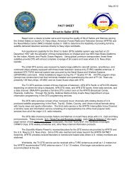
A principle advantage of<br />
circular polarization is the<br />
elimination of the need for<br />
skew adjustment. A feed<br />
designed to receive a linearly<br />
polarized signal must be<br />
correctly lined up with its plane<br />
of polarization to allow<br />
reception of the highest<br />
possible power <strong>and</strong> therefore<br />
clearest picture. It requires a<br />
skew adjustment for finetuning.<br />
However, a feed that<br />
receives a RHCP or LHCP<br />
Figure 4-1 <strong>Satellite</strong> dish parts<br />
signal can be attached at the<br />
focal point of the dish in any<br />
orientation.<br />
There are three noteworthy components of a satellite receive antenna which<br />
collectively capture <strong>and</strong> amplify the signal to a level large enough to break the<br />
receiver reception threshold, normally around negative 45dB. These are the<br />
reflective surface or parabolic curvature, the feedhorn <strong>and</strong> the amplifier section<br />
“Low Noise Amplifier (LNA), Low Noise Block converter (LNB), Low Noise<br />
Converter (LNC), <strong>and</strong> Low Noise Feedhorn (LNF). We will focus on these areas<br />
because they are the components that we personally come in contact with <strong>and</strong><br />
have the greatest control over.<br />
Antenna Reflector<br />
The reflective surface in a perfect world would rely on the geometric properties of<br />
its true parabolic curve to reflect the satellite signal to a very sharp focal point.<br />
The focal point on a parabolic antenna is out in front <strong>and</strong> to the center of the<br />
surface. This would be a well-defined area if a perfect parabolic curve were<br />
defined, however this isn’t as defined as we would prefer. The focal point is not<br />
as perfect as theory would dictate but is still within a small radius <strong>and</strong> is a<br />
defining difference in a perfect or marginal signal reception. This you may say is<br />
where the “rubber meets the road” <strong>and</strong> collection of the signal is critical in this<br />
area.<br />
4-3
Defense Media Center <strong>Satellite</strong> H<strong>and</strong>book V.3.26<br />
Reflective surfaces come in several different shapes <strong>and</strong> sizes but are most<br />
common in the parabolic or offset shape. Offset shaped antennas are nothing<br />
more than a small section of the original parabolic antenna see figure 4-2. The<br />
larger the reflective service the better defined the focal point becomes <strong>and</strong><br />
therefore more gain can be expected. The reflector sometimes mistakenly called<br />
the antenna is the first step in a well-engineered system that will continue to<br />
provide service under harsh<br />
environments. If the size of<br />
your dish is too small for the<br />
signal you intend to capture,<br />
nothing is going to compensate<br />
for that. Working with an<br />
analog signal you could get by<br />
with a smaller dish but suffer<br />
with a noisy picture. A digital<br />
signal on the other h<strong>and</strong> is<br />
perfect or nothing situation <strong>and</strong><br />
with a marginal or less<br />
reflective surface you can<br />
expect nothing.<br />
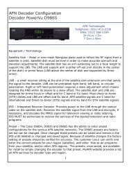
Many of the small aperture Kub<strong>and</strong><br />
dishes sold these days<br />
use an offset antenna, see<br />
figure 4-2, a feedhorn design<br />
which places the focal point<br />
below the front <strong>and</strong> center of<br />
the dish. This type of antenna,<br />
Figure 4-2 An offset satellite antenna<br />
as defined earlier is actually a<br />
small oval subsection from a<br />
much larger parabolic antenna design, is oval in shape with a minor axis (left to<br />
right) that is narrower than its major axis (top to bottom). Because of its unique<br />
geometry, the offset fed antenna requires a specially designed feedhorn, which<br />
matches the antenna geometry precisely. For this reason, the offset fed antenna<br />
<strong>and</strong> feedhorn are usually sold together as a single unit. This type of feed is called<br />
a Low Noise Feed or LNF.<br />
Amplifier “LNA/B/C/F”<br />
The concentrated signal from the reflective surface is channeled to a low noise<br />
amplifier that has a very low noise floor. The job for this section is to amplify the<br />
signal to a level that is above the receiver’s threshold. The Low Noise Amplifier<br />
(LNA) amplifies the signal at the output of the earth station’s antenna. The most<br />
commonly used LNAs use gallium arsenide field effect transistors (GaAsFETs).<br />
Typical noise temperatures of amplifiers produced today range from 15° K to 60°<br />
K (LNB\C\F).<br />
4-4
Defense Media Center <strong>Satellite</strong> H<strong>and</strong>book V.3.26<br />
The LNA is a weather sealed unit that provides enough gain to transport the<br />
signal from the antenna to the receiver. It is located as close the feedhorn as<br />
possible to minimize signal loss <strong>and</strong> thereby improving signal to noise ratio. The<br />
problem with an LNA is that the signal is in several gigahertz frequency range<br />
<strong>and</strong> requires expensive transmission lines to carry the signal from the antenna to<br />
the receiver. A much more efficient way of doing this is to down-convert the<br />
signal at the antenna to a lower frequency for transmission to the receiver. This is<br />
accomplished with the newer LNB/C/F to lower the satellite normal GHz<br />
frequencies to an L-b<strong>and</strong> frequency between 940 MHz to 1450 MHz. For ease of<br />
discussion, all Low Noise Amplifier types will be referred to as a LNB, form this<br />
point forward<br />
There is a basic tradeoff between LNB noise temperature <strong>and</strong> antenna size,<br />
which is gain, expressed by the system figure of merit G/T. Smaller antennas<br />
require a cooler LNB temperature for equivalent system performance. Whereas a<br />
larger antenna allows use of an LNB with a higher noise temperature. This<br />
should not be misunderstood <strong>and</strong> you should not be mislead that an amplifier<br />
with a lower noise temperature will correct for any antenna size. G/T is a<br />
measure of the ability of a receiving system to amplify very weak signals, such as<br />
those of a satellite transmitter 22,300 miles away over the background noise. The<br />
“G” is antenna gain <strong>and</strong> the “T” is its noise temperature. The job for the LNB is to<br />
overcome this noise figure with a carrier to noise C/N separation of greater than<br />
8dB, see Spectrum Analyzer plots. The average for reliable reception of the<br />
AFRTS digital signal is 12dB of signal above the noise floor. It should be noted<br />
also that a digital signal reacts to noise <strong>and</strong> interference differently than a analog<br />
signal. Noise or interference introduced in a digital environment will cause<br />
pixelization <strong>and</strong> even loss of signal reception. Whereas in the analog world,<br />
received video will have noise or sparkles but in most instances would not suffer<br />
total loss of signal. The advantage of the digital signal is, there is no change in<br />
the signal quality until it deteriorates below the receiver reception threshold. But,<br />
at that point the received video will go from perfect to total loss of signal; notice<br />
there is no in between.<br />
The noise figure or temperature, expressed in decibels or degrees Kelvin,<br />
respectively, is a measure of the degree by which this amplifier degrades or<br />
decreases the signal-to-noise ratio of the satellite signal as it passes through the<br />
device. This scale is based on the fact that at a temperature known as absolute<br />
zero, 0° K (equal to minus 273.16° C or minus 459.72° F), molecular motion<br />
ceases <strong>and</strong> consequently all electronic noise disappears. The lower the noise<br />
temperature or figure, the better amplifier performance. There are amplifiers on<br />
the market today with noise temperatures as low as 15°. Getting below 15° K,<br />
requires external cooling of the electronics <strong>and</strong> is a very expensive endeavor.<br />
Gain is also very important in characterizing low noise amplifiers. The more<br />
common LNB gains today usually range from 60 to 70 dB. LNBs must be<br />
designed with sufficient gain to overcome cable losses as well as the effects of<br />
noise contributed within this device <strong>and</strong> overall system noise temperature.<br />
4-5
Defense Media Center <strong>Satellite</strong> H<strong>and</strong>book V.3.26<br />
The low noise block down converter, the LNB, detects the signal relayed from the<br />
feed, converts it to an electrical current, amplifies it <strong>and</strong> down-converts or lowers<br />
its frequency. LNBs in both analog <strong>and</strong> digital systems down-convert the signal to<br />
a b<strong>and</strong> in the 950 to 1450 MHz range. The “down-converted” signal is<br />
subsequently relayed along cable to the indoor satellite receiver.<br />
Signals reaching the input of an LNB from a typical 8-foot C-b<strong>and</strong> dish have<br />
powers of less than 10 –14 watts/m 2 . Therefore, an LNB must contribute very little<br />
noise power or received satellite signals will be drowned out in the roar of<br />
amplifier internal thermal noise. This feat is made possible by advances in<br />
transistor technology. Without such progress, satellite broadcasting would not<br />
exist as we know it today.<br />
LNB Performance<br />
There are three specifications that affect the performance of the LNB <strong>and</strong> have a<br />
direct effect on the ability of a system to satisfactorily capture a satellite signal. In<br />
order of importance for digital reception is, the noise temperature, Local<br />
Oscillator stability (L.O.), <strong>and</strong> its gain expressed in dB. The noise temperature of<br />
the amplifier must be low enough to overcome the noise floor of the antenna to a<br />
minimum of 8dB above the signal to noise floor.<br />
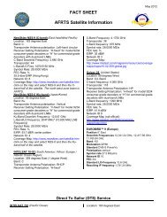
Feedhorn Assembly<br />
Feedhorns, as with the reflective<br />
surface also come in several<br />
different forms with the most<br />
common being the scalar feedhorn.<br />
The scalar feedhorn has a large<br />
circular plate with a series of circular<br />
rings attached to its surface, see<br />
figure 4-3. These rings collect the<br />
signal at the antennas focal point<br />
<strong>and</strong> conduct the incoming signal to<br />
the waveguide attached between the<br />
rings <strong>and</strong> the LNB. The effect of the<br />
scalar rings is to concentrate the<br />
signal in an effort to correct the<br />
Figure 4-3 Feedhorn assembly<br />
imperfections of the parabolic shape.<br />
Therefore the effect of the feedhorn<br />
to focus or channel the incoming signal is critical in signal reception. Adjustment<br />
of the feedhorn will be discussed later but is a must to take advantage of the<br />
systems overall gain <strong>and</strong> therefore reducing the overall system noise floor.<br />
The scalar feedhorn primarily sees or is illuminated by the inner portion of the<br />
antenna’s surface area, while attenuating the signal contribution from the outer<br />
portion of the dish by 8 to 22 dB, depending on whether the dish is deep or<br />
shallow in its construction. Molecular motion within the Earth itself generates<br />
r<strong>and</strong>om noise, which permeates the entire electromagnetic Spectrum used for<br />
4-6
Defense Media Center <strong>Satellite</strong> H<strong>and</strong>book V.3.26<br />
the transmission of satellite signals. This r<strong>and</strong>om noise is many times stronger<br />
than the satellite signals reaching any location. The attenuation or illumination<br />
taper provided by the feed sharply reduces the reception of the Earth noise which<br />
lies just beyond the antenna’s rim. The outer area of the antenna’s surface<br />
therefore acts more as an Earth shield for the feedhorn than as a contributor to<br />
the overall signal gain of the receiving antenna.<br />
Feedhorn Adjustments<br />
Focal length between the center of the<br />
antenna surface hub <strong>and</strong> bottom of the<br />
feedhorn assembly facing the antenna<br />
surface should be initially set to the distance<br />
recommended by the antenna manufacture,<br />
see figure 4-4. Adjustments of 1/8 inch or<br />
more in or out from the recommended<br />
distance should be made while using a signal<br />
meter or Spectrum analyzer to determine the<br />
precise position required for maximum signal<br />
acquisition. This is particularly important for<br />
antennas composed of individual segments,<br />
especially those composed of mesh panels<br />
as antenna surface irregularities due to<br />
careless antenna assembly can actually shift<br />
the optimum position of the focal point from<br />
Figure 4-4 Focal length<br />
the value recommended by the antenna<br />
manufacturer.<br />
When adjusting the feedhorn in or out, be sure that the waveguide opening<br />
remains precisely centered over the dish at all times. You can check this by<br />
measuring from the antenna’s rim to the outer ring of the waveguide opening<br />
from four equidistant positions around the rim. All of these measurements should<br />
be equal.<br />
There is an important difference in the process of aiming an analog <strong>and</strong> a digital<br />
dish. When even a faint signal is received a hint of a television picture appears<br />
with a conventional TVRO. Then fine adjustments can be made to improve<br />
reception. A digital system either acquires the signal or nothing. Therefore the<br />
aiming angles should be set as accurately as possible before powering on. Once<br />
the signal has been acquired, then the signal strength can be monitored for finetuning.<br />
One saving grace with small dish systems is that the beam width is so<br />
wide that aiming errors of even a degree or more will not have a major impact.<br />
While fine-tuning the digital dish monitoring the signal strength is a good<br />
indication of raw RF, but as a word of caution, don’t sacrifice BER for signal<br />
strength.<br />
4-7
Defense Media Center <strong>Satellite</strong> H<strong>and</strong>book V.3.26<br />
Polarization<br />
There are four polarities most common to communications satellites in orbit<br />
today. These are horizontal, vertical, left <strong>and</strong> right h<strong>and</strong> polarization <strong>and</strong> your<br />
system pickup probe must be aligned accordingly for best reception. There are<br />
several different types of feeds: some will need to be manually polarized <strong>and</strong><br />
some will not depending on the type of feedhorn used. This adjustment is best<br />
accomplished while monitoring the satellite signal on the display of a spectrum<br />
analyzer. If a spectrum analyzer isn’t available, make this adjustment <strong>and</strong><br />
maximize the BER of the receiver. Rotate the feedhorn until you begin to see the<br />
other polarization. Turn your receiver on <strong>and</strong> look at the BER. You will notice that<br />
it gets worse as the other polarity begins to increase. The idea is to minimize the<br />
other polarization <strong>and</strong> at the same time maximize the BER or signal quality of<br />
your receiver. If you notice that rotating the feedhorn in a 360 o rotation makes no<br />
difference to the BER/Signal quality. This indicates that your feedhorn is not<br />
adjustable <strong>and</strong> is factory set to the polarization of the satellite transponder <strong>and</strong> no<br />
further adjustments are necessary.<br />
Qualification of <strong>Satellite</strong> Terminals for <strong>Digital</strong> <strong>Reception</strong><br />
The following three subsections include lists of equipment needed to receive the<br />
AFRTS signal. The boxes cover equipment for SATNET C-b<strong>and</strong>, SATNET Kub<strong>and</strong><br />
<strong>and</strong> Television-Direct to Sailor (TV-DTS) C-b<strong>and</strong> digital reception.<br />
Equipment needed for SATNET C-b<strong>and</strong> reception<br />
1. Dish Size: 4.5 meter (minimum size)<br />
2. Mid-b<strong>and</strong> Gain: 43.6 dBi<br />
3. Feedhorn<br />
3.1. For Domestic Region (IntelSat Americas-5) C-b<strong>and</strong> Linear<br />
Vertical Polarization (V)<br />
3.2. For Atlantic Ocean Region: C-b<strong>and</strong> Right H<strong>and</strong> Circular<br />
Polarization (RHCP)<br />
3.3. For Pacific Ocean Region: C-b<strong>and</strong> Left H<strong>and</strong> Circular<br />
Polarization (LHCP)<br />
4. Low Noise Block (LNB)<br />
4.1. Noise Temperature: 25 K (+ -) 5 K<br />
4.2. LO Stability: 1,000 kHz (+ -) 100 kHz<br />
4.3. Recommend using a NORSAT Model 8525F<br />
5. Cable: RG-6 or RG-11<br />
6. L-b<strong>and</strong> Splitter: Caution terminate all unused ports<br />
6.1. Must be diode steerable, power passing on all legs<br />
6.2. Recommend using a Channel Master 1x4 Model. 24141FD<br />
4-8
Defense Media Center <strong>Satellite</strong> H<strong>and</strong>book V.3.26<br />
7. L-b<strong>and</strong> in Line Amplifier<br />
7.1. 20dB gain from .9 .75 (GHz)<br />
7.2. Recommend using a DX Antenna Model ES-25<br />
8. R.F. Connectors<br />
8.1. For RG-6, recommend using Anixter P/N 144017<br />
8.2. For RG-11, recommend using Anixter P/N 095178<br />
Equipment needed for SATNET Ku-b<strong>and</strong> reception<br />
1. Dish Size: 80 centimeters to 1.5 meter (For the size needed in your location,<br />
refer to the satellite footprint maps in chapter 3, figures 3-6 for Japan <strong>and</strong> Korea<br />
or figure 3-7 for Europe.)<br />
2. MidB<strong>and</strong> Gain: 80 CM 37.6 dBi<br />
MidB<strong>and</strong> Gain: 1 meter 39.5 dBi<br />
MidB<strong>and</strong> Gain: 1.2 meter 41.7 dBi<br />
MidB<strong>and</strong> Gain: 1.8 meter 44.5 dBi<br />
3. Feedhorn Ku-b<strong>and</strong> Linear Vertical Polarization (H)<br />
4. Low Noise Block (LNB)<br />
4.1. Noise Temperature: 0.6 to 0.8 dB<br />
4.2. LO Stability: 750 kHz (+ -) 100 kHz<br />
4.3. Recommend using a NORSAT Model 4708C<br />
5. Cable: RG-6 or RG-11<br />
6. L-b<strong>and</strong> Splitter: CAUTION TERMINATE ALL UNUSED PORTS<br />
6.1. Must be diode steerable, power passing on all legs<br />
6.2. Recommend using a Channel Master 1x4 Model 24141FD<br />
7. L-b<strong>and</strong> in Line Amplifier<br />
7.1. 20dB gain from .9 1.75 (GHz)<br />
7.2. Recommend using a DX Antenna Model ES-25<br />
8. R.F. Connectors<br />
8.1. For RG-6, recommend using Anixter P/N 144017<br />
8.2. For RG-11, recommend using Anixter P/N 095178<br />
Equipment needed for Direct to Sailor (DTS) C-b<strong>and</strong> reception<br />
1. Dish size: 1.2 meter<br />
2. MidB<strong>and</strong> Gain: 43.6 dBi<br />
4-9
Defense Media Center <strong>Satellite</strong> H<strong>and</strong>book V.3.26<br />
3. Feedhorn C-b<strong>and</strong> Left H<strong>and</strong> Circular Polarization (LHC)<br />
4. Low Noise Block (LNB)<br />
4.1. Noise Temperature: 20 K (+ -) 5 K<br />
4.2. LO Stability: 500 kHz (+ -) 100 kHz<br />
4.3. Recommend using a NORSAT Model 8520C or California Amplifier<br />
Model 140194.<br />
5. Cable: RG-6 or RG-11<br />
6. L-b<strong>and</strong> Splitter: CAUTION TERMINATE ALL UNUSED PORTS<br />
6.1. Must be diode steerable, power passing on all legs<br />
6.2. Recommend using a Channel Master 1x4 Model. 24141FD<br />
7. L-b<strong>and</strong> in Line Amplifier<br />
7.1. 20dB gain from .9 1.75 (GHz)<br />
7.2. Recommend using a DX Antenna Model ES-25<br />
8. R.F. Connectors<br />
8.1. For RG-6, recommend using Anixter P/N 144017<br />
8.2. For RG-11, recommend using Anixter P/N 095178<br />
Some New Terms You Should Know <strong>and</strong> Underst<strong>and</strong><br />
Moving into the new digital age will require a basic underst<strong>and</strong>ing of a few new<br />
terms that make up this new technology. The following is a brief explanation of<br />
some of the new digital acronyms <strong>and</strong> language that you will come across <strong>and</strong><br />
need to underst<strong>and</strong>.<br />
(1) Receiver/Decoder Threshold: Unlike traditional analog<br />
Receiver/Decoder, where the unit continues to deliver a picture even when<br />
it is operating below the receiver/decoder threshold, digital systems will<br />
not operate below their minimum threshold. The difference being, in the<br />
analog world the picture quality will deteriorate from crystal clear, to noisy<br />
(sparkles) without total loss of picture. The digital receiver will not show<br />
signs of weakened signals <strong>and</strong> it will have a digital cliff where the signal is<br />
no longer processed <strong>and</strong> is discarded. Therefore, you cannot rate the<br />
quality of the signal by comparing it with how good the video is, it’s always<br />
the same above the threshold.<br />
(2) Bit Rate: This is the amount of data information being transmitted in one<br />
second of time. The total stream passing through a single satellite<br />
transponder consists of as many as ten TV services <strong>and</strong> associated audio,<br />
auxiliary audio services, conditional access data, <strong>and</strong> auxiliary data<br />
services such as teletext. The informational bit rate for this transmission<br />
may be as high as 49 mega (million) bits per second (Mb/s) over a 36<br />
MHz satellite transponder. Single video signals within this bit stream will<br />
4-10
Defense Media Center <strong>Satellite</strong> H<strong>and</strong>book V.3.26<br />
have a lower bit rate. For example, a VHS quality movie can be<br />
transmitted at a bit rate of 1.544 Mb/s (T-1); general entertainment<br />
program at 3.0 Mb/s; live sports with a lot of motion at 4. or studio quality<br />
at a rate of more than 8 Mb/s.<br />
(3) Bit Error Rate (BER): Measured in exponential notation, the BER<br />
expresses the performance level of the digital receiver. For example, a<br />
lower BER of 0.0 E-6 is superior to a BER of 1.0 E-3. The lower the BER,<br />
the greater the receiver/decoder’s ability to perform well during marginal<br />
reception conditions, such as during a heavy rainfall or wind gusts.<br />
Depending on which model of Scientific Atlanta Integrated Receiver<br />
Decoder (IRD) being used, the quality of the received signal is<br />
represented in BER or a signal quality scale of 1-10; 10 being the best.<br />
The 9223 will represent signal quality in BER <strong>and</strong> the 9234 set-top<br />
measures quality on a scale of 1 to 10.<br />
Sun Outages<br />
A sun outage is similar in behavior to a rain fade. The high energy level <strong>and</strong><br />
broadb<strong>and</strong> nature of the sun's energy can overpower a satellites downlink signal<br />
<strong>and</strong> effectively wash out a receive signal with noise. This problem is technically<br />
impossible to overcome at this time.<br />
Due to the angle of the sun in relationship to the satellite, a sun outage is actually<br />
a mixture of degraded receive performance with the possibility of a circuit outage.<br />
A circuit outage might be typically 20% of the total predicted sun outage duration<br />
period. Many factors influence how robust a receive circuit may be, therefore it is<br />
extremely difficult to predict exactly how long an outage might possibly be. The<br />
digital nature of the AFRTS signal means that you’ll either have very good signal<br />
or none at all with very short periods of degraded “pixilated” signal.<br />
At certain times of year, approximately one month either side of the spring <strong>and</strong><br />
autumn equinoxes, there may be a conjunction of the sun <strong>and</strong> satellite positions.<br />
Depending upon the size of the earth station antenna, such events can lead to a<br />
serious impairment of the space-earth link.<br />
The outages typically last only a few minutes at a time once a day with a normal<br />
worse case outage of about ten to fifteen minutes. Outages will affect each link in<br />
multi-hop circuits. For example viewers in Europe or the Indian Ocean area<br />
would be affected by an outage of first, the Atlantic satellite <strong>and</strong> then secondly, of<br />
the actual satellite feeding their antenna.<br />
Antennas should not be adjusted or re-pointed at these lost-of-signal times. The<br />
viewer should wait out the outage until the sun finishes passing directly behind<br />
the satellite.<br />
RF Interference in <strong>Digital</strong> Networks<br />
The transmission of digitally compressed video over satellite allows many high<br />
quality video signals to be transmitted in a satellite transponder, which formerly<br />
could accommodate only a single high quality video signal. The “compression” of<br />
4-11
Defense Media Center <strong>Satellite</strong> H<strong>and</strong>book V.3.26<br />
these services into a narrow b<strong>and</strong>width causes some inevitable trade-offs in the<br />
complexity of both the transmit <strong>and</strong> receive earth stations. Transmit earth<br />
stations must be equipped with tremendously complex video “encoders” which<br />
digitize <strong>and</strong> compress the large amounts of video <strong>and</strong> audio information into a<br />
much smaller b<strong>and</strong>width. Receive earth stations must be compatible with the<br />
reception of a wide b<strong>and</strong> digital carrier. While most Television / Receive-Only<br />
(TVRO) earth stations are compatible with the digital video technology, some will<br />
be susceptible to <strong>Radio</strong> Frequency Interference (RFI), sources which were not<br />
significant with analog video transmissions.<br />
In the traditional analog world, interference was spread across a much broader<br />
information base where individual elements of information were less critical. With<br />
digital compression, much more information is transmitted in a compressed<br />
format, which increase the importance of each “Information packet”. <strong>Digital</strong><br />
compression signals react differently to problems caused by RF Interference in<br />
the RF (<strong>Radio</strong> Frequency) path as compared with traditional analog video<br />
signals. Where RF Interference caused either a white line, sparkle or “hum” bar<br />
in the Analog video realm, in the digital domain it can result in digital artifacts<br />
such as “blocking”’ <strong>and</strong>/or a “black screen” or “freeze frames” depending upon<br />
the magnitude <strong>and</strong> duration of the interference <strong>and</strong> the concealment algorithms<br />
used.<br />
TVRO sites experiencing RFI do not always experience any observable effects.<br />
A typical transponder operating with a compressed digital video signal may<br />
contain up to 8 television programs. Although one might expect each of these<br />
signals to be 8 times as susceptible to RFI as a traditional analog signal; in<br />
practice the signals are of a higher quality (for a given antenna size) than<br />
traditional analog transmission due to the sophisticated error correction <strong>and</strong><br />
concealment algorithms employed.<br />
Much has been learned about the cause <strong>and</strong> mechanics of many external<br />
interfering sources that enter through the antenna <strong>and</strong> associated subsystems.<br />
This paper will help identity potential origins of RF Interference in addition to<br />
providing methods of reducing the effects of interference on the satellite carrier.<br />
While it is impossible to eliminate RFI, there are ways in which to both reduce the<br />
level of interference <strong>and</strong> conceal the event so that it has the least amount of<br />
perceived effect on the video.<br />
We will address two major interference scenarios, which may be caused by a<br />
number of ground-based sources. These sources <strong>and</strong> their method of interaction<br />
with a typical receive terminal are explained. Several methods of reducing the<br />
interference <strong>and</strong> its effects are also explored.<br />
The two types of RFI encountered are Destructive Interference (DI) <strong>and</strong> Out of<br />
B<strong>and</strong> Interference (OBI). Destructive interference is encountered when the<br />
desired receive signal is completely overwhelmed, or disrupted, by an interfering<br />
signal (or noise source) in the channel of the desired signal, <strong>and</strong> at a level equal<br />
to or greater than the desired signal. Out of B<strong>and</strong> Interference is defined as a<br />
signal (or noise source) which does not interact directly with the desired signal,<br />
4-12
Defense Media Center <strong>Satellite</strong> H<strong>and</strong>book V.3.26<br />
but interacts with other components of the receive system such that the desired<br />
signal is impaired or destroyed. Both DI <strong>and</strong> OBI may originate from the same<br />
sources. An interfering carrier from a terrestrial microwave system may act as DI<br />
on a carrier at one frequency, <strong>and</strong> an OBI on carrier at another frequency at the<br />
same TVRO site.<br />
Current Technology<br />
<strong>Digital</strong> video compression receivers differs from traditional FM video receivers in<br />
that they receive video <strong>and</strong> audio signals that are digitized, compressed <strong>and</strong><br />
modulated using Quadrature Phase Shift Keyed (QPSK) digital modulation. This<br />
technique allows the transmission <strong>and</strong> reception of several high quality video<br />
channels <strong>and</strong> associated audio in a 36MHz transponder. In comparison,<br />
traditional analog FM modulation provides only one video <strong>and</strong> its associated<br />
audio signals to be transmitted per transponder.<br />
Error Correction<br />
Because of the increased capacity attained using digital compression <strong>and</strong><br />
transmission, special error protection is used to either correct errors or provide<br />
concealment when the error rate exceeds the capability for the decoder to<br />
provide complete correction. To detect <strong>and</strong> correct errors caused by thermal<br />
noise, a technique called soft decision convolutional decoding is used. The IRD<br />
<strong>and</strong> associated up-link equipment use a convolutional encoder to provide error<br />
correction to thermal noise down to about 7 dB C/N. Also, to protect against burst<br />
noise interference, a special data interleave <strong>and</strong> Reed Solomon block decoder<br />
are used. The combination provides error correction to burst interference outages<br />
that can be caused by engine ignition noise, industrial microwave oven<br />
interference, <strong>and</strong> adjacent b<strong>and</strong> interference from such sources as aircraft radar<br />
altimeters.<br />
Because there may be instances when the error rate is high enough so that not<br />
all errors can be corrected, the IRD contains sophisticated software algorithms<br />
that provide image concealment for small-uncorrected errors, <strong>and</strong> either freeze<br />
frames or black-frame substitution for larger uncorrected errors.<br />
The FM Analog equivalent to digital errors is the well-known “white line” or<br />
“sparkles that appears on the TV screen when the received signal level drops<br />
below the FM threshold of about 10dB C/N. Unlike analog transmission where<br />
the “white lines” or “sparkles” are superimposed on the video, uncorrected digital<br />
errors can create a loss of digital synchronization resulting in outages that can<br />
last longer than the actual duration of the interference. It is during these<br />
instances that image concealment is important Typically, instead of a single<br />
“white fine” or “sparkle”, a digital error can result in the generation of artifacts<br />
ranging from ”no perceptible error” to “multiple block errors” that look like FM<br />
threshold sparkles to “freeze frames” or “black screens” for really significant<br />
errors.<br />
4-13
Defense Media Center <strong>Satellite</strong> H<strong>and</strong>book V.3.26<br />
Reacquisition<br />
Improvements in technology against terrestrial interference focus on two primary<br />
areas, reacquisition of the carrier, <strong>and</strong> concealment. Reacquisition deals with the<br />
time it takes to reacquire the carrier, decode <strong>and</strong> restore video after an RFI “hit”<br />
takes place. Reduction of the reacquisition time to its lowest value is the<br />
objective in any design consideration.<br />
Concealment<br />
Concealment deals with the methods employed in the IRD as it relates to video<br />
presented to the viewing audience during the reacquisition period. Various<br />
approaches can be employed, use of a “black screen”, displaying digital artifacts,<br />
or freezing the video frame are all methods that can be used to display video<br />
during the reacquisition sequence.<br />
Sources of Interference<br />
There are a variety of sources of interference, which can affect a digital<br />
compression path. Identification of the interfering source is an important step in<br />
the goal of reducing the effects of RF interference on the desired signal.<br />
Interference can have two effects on a digital carrier:<br />
1) Compression or saturation of the RF receiving equipment including LNA’s,<br />
LNB’s, line amplifiers, <strong>and</strong> RF Tuner inside the IRD.<br />
2) Direct corruption of the digital carrier.<br />
There are three areas, which need to be addressed in protecting the digital<br />
carrier against interfering sources:<br />
1. Protection from saturation or compression in the RF path<br />
2. Error correction <strong>and</strong> reacquisition of the digital carrier<br />
3. Concealment with regard to the source material displayed to the<br />
viewing audience.<br />
The following section details the potential sources of RF Interference.<br />
Terrestrial Microwave Interference<br />
Much of the world’s populated areas are utilizing terrestrial microwave signals.<br />
These signals range from typically 2 GHz to 15 GHz with a major concentration<br />
in the 3.1 GHz to 4.99 GHz b<strong>and</strong>. Terrestrial microwave transmitter/antennas will<br />
be located at or near places of commerce, metropolitan areas, near airports, or<br />
large industrial facilities. Microwave repeaters may be found at intermediate<br />
points in the path throughout populated <strong>and</strong> often times unpopulated regions.<br />
Most terrestrial microwave interference manifests itself as a single modulated or<br />
unmodulated carrier, <strong>and</strong> is readily observable in the C-b<strong>and</strong> pass b<strong>and</strong> of the<br />
system with a Spectrum analyzer. A site survey should be performed prior to final<br />
location of the earth station to ensure that terrestrial microwave carriers will not<br />
be a problem. Microwave interference may require relocation of the satellite-<br />
4-14
Defense Media Center <strong>Satellite</strong> H<strong>and</strong>book V.3.26<br />
receiving antenna into a “clear” path. Should the presence of these carriers be<br />
detected prior to site location, they can be treated as part of the satellite link<br />
analysis to evaluate their affect on performance.<br />
Impulse <strong>and</strong> Ignition Noise<br />
A digitally compressed video signal can be susceptible to interference from<br />
impulse generators. Some typical sources of impulse noise are power equipment<br />
(power generators) or ignition noise from engines (vehicles, motorcycles,<br />
mopeds, lawn mowers, power blowers). Spark emissions cover a wide b<strong>and</strong> of<br />
RF frequencies including C-b<strong>and</strong> <strong>and</strong> can enter through the satellite dish <strong>and</strong><br />
LNB. These emissions can originate from engines where broken, intermittent or<br />
“arcing” spark plug cables are used. Ignition wires are typically resistive wires<br />
that dampen RF radiation, however a broken or intermittent ignition wires can arc<br />
<strong>and</strong> emit excessive radio interference. Ignition “burst noise” can last in excess of<br />
1 millisecond, exceeding the interleave depth of the error correction system<br />
designed into the IRD <strong>and</strong> can have a power level 40 dB higher than the satellite<br />
carrier. The repetition rates greater than once every 70 millisecond have been<br />
detected.<br />
When planning an earth station you should site the station well away from<br />
sources of ignition interference such as busy roads, highways, intersections, or<br />
car parks. You may want to restrict the use of gasoline-powered lawn mowers<br />
<strong>and</strong> other combustion engines during peak usage hours.<br />
Because ignition noise represents broadb<strong>and</strong> interference an operator<br />
experiencing ignition noise should address both the issue of saturation as well as<br />
attempt to reduce the magnitude of the interfering source. To address saturation,<br />
attenuators should be utilized both at C-b<strong>and</strong> (if used) <strong>and</strong> L-b<strong>and</strong>. An interfering<br />
carrier from a automobile ignition can be more than 40 dB higher than the<br />
receiving signal <strong>and</strong> saturate LNB’s, line amplifiers <strong>and</strong> the RF tuner in the<br />
satellite receiver. Severe ignition noise problems can be addressed by relocation<br />
of the receiving antenna, use of an “earth berms”, or installation of an RFI<br />
grounded fence between the interfering sources <strong>and</strong> the earth station antenna.<br />
Aircraft Radar Altimeters/Airport Ground Radar<br />
If your downlink antenna is located near an airport or flight path your system can<br />
pick up interfering carriers from aircraft radar altimeters. The radar altimeter<br />
Spectrum is 4.200 to 4.400 GHz. This corresponds to 750 to 950 MHz at the Lb<strong>and</strong><br />
output of the LNB. These carriers have been measured in excess of<br />
+40dBc relative to the desired satellite carrier. This kind of interference often<br />
results in the saturation of any line amplifiers to the extent that the amplitude of<br />
the desired Spectrum is reduced below a measurable level. The effects of this<br />
interference may last several seconds until the aircraft passes out of the earth<br />
station antenna beam. The interference appears as a chirp or energy spread<br />
over the indicated Spectrum. It is first observed as a low level signal <strong>and</strong><br />
gradually builds to its maximum level before gradually diminishing.<br />
4-15
Defense Media Center <strong>Satellite</strong> H<strong>and</strong>book V.3.26<br />
These interfering carriers are usually out-of-b<strong>and</strong> <strong>and</strong> can be dealt with by<br />
installing a C-b<strong>and</strong> block filter that can be specifically manufactured for greater<br />
protection at the aircraft radar frequency.<br />
Other potential sources of interference from airports are ground looking radar<br />
that can saturate LNA/LNB’s. Frequency coordination in some countries allow for<br />
adjacent b<strong>and</strong>s to be utilized where they can cause out-of-b<strong>and</strong> interference.<br />
Once again, C-b<strong>and</strong> b<strong>and</strong> pass or block filters remain an effective means of<br />
controlling the interfering carrier.<br />
Ship-board Radar<br />
Another potential source of interference in coastal areas is shipboard naval<br />
radar. Usually, this on-board radar is not supposed to be utilized within a radius<br />
of the shore; however, there are documented cases where this radar has been<br />
“turned on” with deleterious effects to the local coastal viewing audience.<br />
Commercial Microwave Ovens<br />
Commercial microwave ovens operating in fast-food chains <strong>and</strong> earth station<br />
lunchrooms are potential sources of interference. Emissions levels allowed by a<br />
microwave oven can be as much as 20 dB higher than a C-b<strong>and</strong> satellite carrier;<br />
however, microwave oven manufactures are normally required to replace units<br />
that are known to interfere with commercial broadcast systems. A typical<br />
operating frequency for a microwave oven is 2250 MHz with a considerable<br />
amount of wide b<strong>and</strong> noise generated in the 3900 MHz to 4500 MHz range. This<br />
noise can become more apparent over the life of the magnetron <strong>and</strong> can be<br />
prevalent near the end of its useful life.<br />
Walkie-Talkies<br />
Walkie-talkies have been observed to interfere with the operation of IRDs.<br />
Operating a walkie-talkie in the vicinity of the IRD can interfere with the operation<br />
of the IRD. Restricted use of walkie-talkies is recommended in the vicinity of a<br />
downlink earth station.<br />
Cell Phones<br />
Cell (Cellular) Telephones operate in the 900 Mhz range <strong>and</strong> can directly<br />
interfere with the down converted (IF) signal from the LNB to the IRD. The<br />
activation of a cell phone unit near the IRD may generate unacceptable<br />
destructive or out of b<strong>and</strong> interference which may enter the IRD through poorly<br />
shielded cabling or improperly terminated dividers <strong>and</strong> connectors.<br />
R<strong>and</strong>om RFI (Fluorescent <strong>and</strong> Sodium Vapor Lamps, Lightning)<br />
Particularly on start-up, fluorescent lamps can flicker causing an interfering<br />
source to an earth station antenna nearby. Another potential source is sodium<br />
vapor lamps when in a “failed” condition. Lightning is another known source of<br />
RFI that can effectively wipeout both digital <strong>and</strong> analog carriers. Though these<br />
sources are not a common occurrence, they should be mentioned in the<br />
investigation of a RFI occurrence.<br />
4-16
Protection from Interference<br />
Defense Media Center <strong>Satellite</strong> H<strong>and</strong>book V.3.26<br />
Selecting a site<br />
Site selection is the most important pro-active stop an earth station operator can<br />
take in prevention of terrestrial interference. Busy roads <strong>and</strong> highways, parking<br />
lots, power generators, <strong>and</strong> power equipment near the receiving antenna are all<br />
potential sources of interference. Sites located near airports may need special<br />
consideration due to aircraft radar altimeters.<br />
Saturation <strong>and</strong> Compression<br />
Many traditional earth station operators in the analog environment are concerned<br />
with obtaining the highest signal level possible for their analog receiving<br />
equipment High signal levels in the digital environment can be problematic where<br />
terrestrial interference is present<br />
Ignition noise is a common problem where saturation can occur in the RF path.<br />
Interfering carriers can potentially be 40 dB higher than the satellite carrier<br />
resulting in compression of the RF subsystems.<br />
Optimizing signal levels through the use of C-b<strong>and</strong> <strong>and</strong> L-b<strong>and</strong> attenuator pads<br />
to increase the “headroom” of the system where RFI is found can dramatically<br />
improve performance of the receiving equipment. Installation of 6dB <strong>and</strong> 10dB<br />
pads in front of line amplifiers, block down converters, <strong>and</strong> video<br />
receiver/decoders can provide the additional “headroom” needed to prevent<br />
saturation during a RFI hit. Operating IRD’s in a “low gain” mode is another<br />
useful way to add additional “headroom” for RFI “hits”.<br />
Many earth station operators utilize line amplifiers in traditional analog systems,<br />
which can aggravate the effect of RFI <strong>and</strong> compression. Signals that are spiked<br />
due to RFI in combination with a high gain line amplifier can saturate<br />
downstream block down converters <strong>and</strong> RF tuners inside the IRD. Optimization<br />
of the RF path, including line amplifiers is necessary when combating RFI.<br />
Out-of-b<strong>and</strong> Filtering<br />
For sites experiencing aircraft radar or out-of-b<strong>and</strong> interference, C-b<strong>and</strong> filtering<br />
in front of the LNA/LNB is an effective way to protect from interfering carriers.<br />
Special notch filters have been made for aircraft radar that are effective in those<br />
specific locations near airports or aircraft approaches.<br />
RFI (<strong>Radio</strong> Frequency Interference) Fencing<br />
Special RFI fencing can often reduce the source of interfering carriers or ignition<br />
noise where it is present Wire fences of the proper diameter, located between the<br />
interfering source <strong>and</strong> the earth station antenna can be an effective way of<br />
dealing with terrestrial interference. Fences that can be utilized for RFI protection<br />
can be as simple as fine wire mesh of galvanized steel, property grounded that<br />
roughly meets the desired dimensions of 1/10 wavelength beyond cutoff of the Cb<strong>and</strong><br />
carrier. It is important to install the fence at the proper height <strong>and</strong> distance<br />
4-17
Defense Media Center <strong>Satellite</strong> H<strong>and</strong>book V.3.26<br />
from the earth station antenna, with special attention being paid to the<br />
construction, (galvanized steel is preferred).<br />
A wire mesh fence, property constructed, will scatter-back <strong>and</strong> absorb the energy<br />
<strong>and</strong> appear to the interfering signal much like a solid sheet of metal. The<br />
optimum dimension for the mesh fencing is a mesh size smaller than 1.27cm,<br />
(1/2 inch), which offers adequate protection at C-b<strong>and</strong>.<br />
To block ignition impulse noise from a busy street or parking lot, a galvanized<br />
steel fence with a mesh size smaller than 1.27cm (1/2 inch), should be grounded<br />
with copper grounding rods or chemical ground system. The wire fence in<br />
combination with the ground system should accommodate a wide variation of RF<br />
emissions generated from engine ignition systems. Effective fences that have<br />
also been utilized in the past are fine wire mesh <strong>and</strong> solid thin sheet metal<br />
barriers.<br />
Earth Berms<br />
A more drastic but very effective manner to protect from terrestrial interference is<br />
the use of earth berms. Placing the antenna below ground level, while more<br />
costly <strong>and</strong> not always practical, it still provides an excellent manner in which to<br />
protect the integrity of the receiving signal from RFI.<br />
When constructing a “earth berms” careful considerations should be given to the<br />
side lobes of the antenna since the noise temperature of the earth is much higher<br />
than that of the dark sky. The surrounding earth in the earth berms may cause a<br />
noise figure degradation if it is not significantly outside of the antenna side lobe.<br />
Summary<br />
<strong>Digital</strong> Video Compression systems will continue to be the choice for future<br />
satellite video broadcasting because of the b<strong>and</strong>width efficiency <strong>and</strong><br />
unsurpassed video quality. The traditional FM analog approach to earth<br />
station operation will enter a new era with the advent of video<br />
compression. Many video earth station operators are learning the same<br />
sensitivities to RFI as the traditional digital common carriers (IDR)<br />
networks used in the telecommunications industry. Through education of<br />
earth station operators, adaptation to the environment, <strong>and</strong> advances in<br />
technology, digital compression systems will become the st<strong>and</strong>ard in<br />
satellite video broadcast delivery throughout the world. Education <strong>and</strong><br />
underst<strong>and</strong>ing of the effects of terrestrial interference, <strong>and</strong> its prevention,<br />
are the most important steps in achieving the high st<strong>and</strong>ard of service<br />
dem<strong>and</strong>ed by subscribers in the worldwide marketplace.<br />
Table 4-1 Spectrum Analyzer Setup<br />
1. Connect the input of the spectrum analyzer with a T-connector between the LNB <strong>and</strong><br />
the receiver. Caution: This will put 13-19 volts DC on the input of the spectrum<br />
analyzer <strong>and</strong> could damage it. To prevent this from happening use a DC blocker on<br />
4-18
Defense Media Center <strong>Satellite</strong> H<strong>and</strong>book V.3.26<br />
the input of the analyzer while still feeding the LNB with the required receiver DC<br />
voltage. This will allow you see spectrum plot for the signal you intend to capture.<br />
2. Set the frequency to satellite L-b<strong>and</strong> frequency between 950 MHz <strong>and</strong> 1450 MHz.<br />
3. Span to 100 MHz.<br />
4. Amplitude to –45 dB<br />
5. Vertical scale to 1 dB per scale. If signal is out of range adjust accordingly<br />
a. Freq. Mode<br />
b. Frequency<br />
c. Polarization<br />
d. FEC Rate<br />
e. Symbol Rate<br />
f. L.O. Freq<br />
g. Video St<strong>and</strong>ard (NTSC)<br />
Table 4-2 Typical <strong>Satellite</strong> Receiver Setup<br />
9234 9223<br />
4-19<br />
a. B<strong>and</strong><br />
b. L-b<strong>and</strong> Freq<br />
c. Polarization<br />
d. FEC Rate<br />
e. Symbol Rate<br />
f. L.O. Freq<br />
g. Video St<strong>and</strong>ard (NTSC)
Defense Media Center <strong>Satellite</strong> H<strong>and</strong>book V.3.26<br />
Table 4-3 Bit Error Rate (BER) to Threshold Margin Table<br />
Bit Error Rate Reading SatNet FEC ¾ DTS FEC 2/3<br />
2.00E-02 -- 0.22<br />
1.00E-02 0.36 1.44<br />
5.00-03 1.36 2.36<br />
2.00-03 2.38 3.36<br />
1.00E-03 3.12 4.10<br />
5.00E-04 3.78 4.76<br />
2.00E-04 4.56 5.54<br />
1.00E-04 5.08 6.10<br />
5.00E-05 5.58 6.60<br />
2.00E-05 6.14 7.12<br />
1.00E-05 6.50 7.48<br />
5.00E-06 6.78 7.78<br />
2.00E-06 7.18 8.18<br />
1.00E-06 7.42 8.46<br />
Note: The information shown is the amount of margin, in dB, over the DVB specification threshold<br />
for a given BER display. For example, a BER reading of 5.00E – 04 on a SATNET decoder<br />
provides 3.78 dB of margin over the Eb/No threshold of 5.5 dB or a total Eb/No of 9.28 dB. At the<br />
same BER, DTS provides 4.76 dB of margin over the Eb/No threshold of 5.0 dB for a total Eb/No<br />
of 9.76 dB.<br />
Scientific Atlanta developed the table from actual testing of decoders over a range of symbol<br />
rates. The st<strong>and</strong>ard deviation is 0.2 dB.<br />
4-20