

Suppressing Acoustic Noise in PWM Fan Speed Control ... - Microchip
Suppressing Acoustic Noise in PWM Fan Speed Control ... - Microchip
Suppressing Acoustic Noise in PWM Fan Speed Control ... - Microchip

Create successful ePaper yourself
Turn your PDF publications into a flip-book with our unique Google optimized e-Paper software.
AN771<br />
ACOUSTIC NOISE SOURCES<br />
The most dom<strong>in</strong>ant source of acoustic fan noise is turbulent<br />
airflow, which is caused by fan operation at full<br />
speed. Employ<strong>in</strong>g fan speed control (where the fan is<br />
operated primarily at lower than full speed) m<strong>in</strong>imizes<br />
this noise. The second most dom<strong>in</strong>ant acoustic noise is<br />
due to BDC fan’s torque characteristic. As shown <strong>in</strong><br />
Figure 2 and Figure 3, stator excitation is a square<br />
wave that is switched “on” 45° before peak torque position<br />
and switched “off ” 45° after peak torque position.<br />
This excitation causes a small amount of ripple <strong>in</strong> motor<br />
torque at the frequency of commutation. Each small<br />
torque “burst” causes a m<strong>in</strong>ute flex<strong>in</strong>g of the entire fan<br />
structure and results <strong>in</strong> a fa<strong>in</strong>t (but audible) “tick<strong>in</strong>g”<br />
noise while the BDC fan is operat<strong>in</strong>g (Figure 2).<br />
<strong>Acoustic</strong> <strong>PWM</strong> noise is generated <strong>in</strong> exactly the same<br />
way. When the <strong>PWM</strong> pulse turns on, a step change <strong>in</strong><br />
torque occurs with<strong>in</strong> the fan, the profile of which<br />
matches the rise time of the <strong>PWM</strong> pulse (Figure 3).<br />
This impulse torque is articulated by the fan structure<br />
as audible noise. This is true mostly <strong>in</strong> larger fans (i.e.,<br />
fans with operat<strong>in</strong>g currents <strong>in</strong> excess of 300 mA),<br />
s<strong>in</strong>ce they generate a greater amount of torque and<br />
have larger size and mass. This effect is also more pronounced<br />
at low operat<strong>in</strong>g speeds (i.e., low <strong>PWM</strong> duty<br />
cycle): the lower the <strong>PWM</strong> duty cycle, the greater the<br />
percentage of time the fan is “off” (quiet) and the more<br />
noticeable the acoustic noise caused by the <strong>PWM</strong><br />
becomes.<br />
Commutated<br />
Torque<br />
Torque<br />
Peak Torque Po<strong>in</strong>ts<br />
45 90 135 180 225 270 315 360<br />
Electrical Degrees<br />
Commutation Po<strong>in</strong>t<br />
FIGURE 2: BDC <strong>Fan</strong> Torque<br />
Characteristics (<strong>Fan</strong> Runn<strong>in</strong>g Cont<strong>in</strong>uously).<br />
<strong>PWM</strong> OFF <strong>PWM</strong> ON<br />
x x + 90<br />
Electrical Degrees<br />
Commutation Po<strong>in</strong>t<br />
FIGURE 3: BDC <strong>Fan</strong> Torque<br />
Characteristics (<strong>PWM</strong> <strong>Control</strong>).<br />
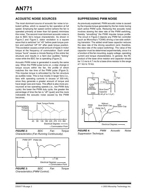
SUPPRESSING <strong>PWM</strong> NOISE<br />
As previously expla<strong>in</strong>ed, <strong>PWM</strong> acoustic noise is caused<br />
by the impulse torque generated by the fan motor dur<strong>in</strong>g<br />
each active <strong>PWM</strong> cycle. Reduc<strong>in</strong>g this acoustic noise<br />
<strong>in</strong>volves slow<strong>in</strong>g the slew rate of the <strong>PWM</strong> switch<strong>in</strong>g,<br />
thereby “smooth<strong>in</strong>g” the <strong>PWM</strong> impulse torque profile.<br />
The circuit <strong>in</strong> Figure 3 depicts any <strong>PWM</strong> fan controller<br />
(such as <strong>Microchip</strong>’s TC646) driv<strong>in</strong>g a low-side switch<strong>in</strong>g<br />
transistor. The added small base capacitor reduces<br />
the slew rate of the driv<strong>in</strong>g waveform (and, therefore,<br />
the slew rate of the output switch<strong>in</strong>g). The value of the<br />
capacitor must be determ<strong>in</strong>ed experimentally, s<strong>in</strong>ce it is<br />
a function of the fan mount<strong>in</strong>g, supply voltage, operat<strong>in</strong>g<br />
current and torque characteristics. In general, the RC<br />
product of the base drive resistor and capacitor should<br />
be 1.0 ms to 4.7 ms for a base drive resistor <strong>in</strong> the range<br />
of 1 kΩ to 10 kΩ.<br />
FIGURE 4: <strong>PWM</strong> <strong>Acoustic</strong> <strong>Noise</strong><br />
Suppression Technique.<br />
DS00771B-page 2 © 2003 <strong>Microchip</strong> Technology Inc.<br />
Torque<br />
V DD<br />
VDD RBASE (1 kΩ to 10 kΩ)<br />
OUT<br />
<strong>PWM</strong><br />
<strong>Fan</strong><br />
<strong>Speed</strong><br />
<strong>Control</strong>ler Slow-Down<br />
GND<br />
Capacitor<br />
(0.40 µF to 1.0 µF)<br />
<strong>PWM</strong><br />
OFF<br />
V FAN<br />
Electrical Degrees<br />
<strong>Fan</strong><br />
Without<br />
Slow-Down Cap With<br />
Slow-Down Cap<br />
<strong>PWM</strong> ON


