Sub Module 2.9 - nptel - Indian Institute of Technology Madras
Sub Module 2.9 - nptel - Indian Institute of Technology Madras
Sub Module 2.9 - nptel - Indian Institute of Technology Madras

Create successful ePaper yourself
Turn your PDF publications into a flip-book with our unique Google optimized e-Paper software.
Mechanical Measurements Pr<strong>of</strong>. S.P.Venkateshan<br />
<strong>Indian</strong> <strong>Institute</strong> <strong>of</strong> <strong>Technology</strong> <strong>Madras</strong><br />
U – Tube manometer<br />
<strong>Sub</strong> <strong>Module</strong> <strong>2.9</strong><br />
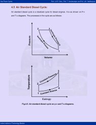
The simplest <strong>of</strong> the gages that is used for measuring pressure is a U – tube<br />
manometer shown in Figure 63. The U tube needs to be vertically oriented<br />
and the acceleration due to gravity is assumed to be known. The height ‘h’ is<br />
the measured quantity.<br />
.<br />
p pa<br />
A<br />
h<br />
Figure 63 U tube manometer<br />
The pressure to be measured is that <strong>of</strong> a system that involves a fluid (liquid or<br />
a gas) different from the manometer liquid. Let the density <strong>of</strong> the fluid whose<br />
pressure being measured be ρf and that <strong>of</strong> the manometer liquid be ρf.<br />
Equilibrium <strong>of</strong> the manometer liquid requires that there be the same force in<br />
the two limbs across the plane AA. We then have<br />
p+ ρ gh= p + ρ gh<br />
(62)<br />
f a m<br />
This may be rearranged to read<br />
( ρ ρ )<br />
A<br />
g<br />
Tubes <strong>of</strong><br />
equal diameter<br />
p − pa = m − f gh<br />
(63)<br />
Even though mercury is a common liquid used in manometers, other liquids<br />
are also used. A second common liquid is water. When measuring pressures<br />
close to the atmospheric pressure in gases, the fluid density may be quite
Mechanical Measurements Pr<strong>of</strong>. S.P.Venkateshan<br />
<strong>Indian</strong> <strong>Institute</strong> <strong>of</strong> <strong>Technology</strong> <strong>Madras</strong><br />
negligible in comparison with the manometer liquid density. One may then<br />
use the approximate expression<br />
p − p ≈ ρ gh<br />
(64)<br />
a m<br />
The manometer liquid is chosen based on its density with respect to the<br />
density <strong>of</strong> the fluid whose pressure is being measured and also the pressure<br />
difference that needs to be measured. Indeed small pressure differences are<br />
measured using water or organic liquids as the manometer liquid such that<br />
the height h measured is sufficiently large as to be estimated with sufficient<br />
precision.
Mechanical Measurements Pr<strong>of</strong>. S.P.Venkateshan<br />
<strong>Indian</strong> <strong>Institute</strong> <strong>of</strong> <strong>Technology</strong> <strong>Madras</strong><br />
Example 22<br />
a) A U tube manometer employs special oil having a specific gravity <strong>of</strong><br />
0.82 as the manometer liquid. One limb <strong>of</strong> the manometer is exposed<br />
to the .atmosphere at a pressure <strong>of</strong> 740 mm Hg and the difference in<br />
column heights is measured as 20 cm± 1 mm when exposed to an air<br />
source at 25°C. Calculate the air pressure in Pa and the uncertainty.<br />
b) The above manometer was unfortunately mounted with an angle <strong>of</strong><br />
3° with respect to the vertical. What is the error in the indicated<br />
pressure due to this, corresponding to the data given above?<br />
Part a<br />
Specific gravity uses the density <strong>of</strong> water at 25°C as the reference.<br />
From table <strong>of</strong> properties, the density <strong>of</strong> water at this temperature is 996<br />
kg/m 3 . The density <strong>of</strong> the manometer liquid is<br />
ρm= ρSpecial<br />
oil<br />
= Specific gravity <strong>of</strong> special oil × Density <strong>of</strong> water at 25°<br />
C<br />
3<br />
= 0.82× 996 = 816.7 kg / m<br />
Air density is calculated using the ideal gas relation. The gas constant<br />
for air is taken as Rg = 287 J/kg K. The air temperature is T =<br />
273+25=298 K. The air pressure is converted to Pa as<br />
740 5<br />
1.013 10 98634.2<br />
pa = ×<br />
760<br />
Air density is thus given by<br />
× = Pa<br />
pa<br />
98634.2<br />
3<br />
ρ f = = = 1.15 kg / m<br />
RT g 287× 298<br />
The column height is given to be h = 20 cm = 0.2 m. The measured<br />
pressure differential is then given by<br />
( )<br />
p − pa= 816.7 − 1.15 × 9.8× 0.2 = 1598.48 Pa<br />
The uncertainty calculation is straight forward. It is the same as the %<br />
uncertainty in the column height i.e.<br />
error in the measured pressure difference is<br />
0.001<br />
Δ h%<br />
=± × 100 =± 0.5 . The<br />
0.2
Mechanical Measurements Pr<strong>of</strong>. S.P.Venkateshan<br />
<strong>Indian</strong> <strong>Institute</strong> <strong>of</strong> <strong>Technology</strong> <strong>Madras</strong><br />
0.5<br />
Δ( p− pa) =± × 1598.48 =± 7.99 ≈ 8 Pa<br />
100<br />
Part b<br />
It is clear that the manometer liquid height difference is given<br />
by h'= hcos3°= 0.2× 0.9986 = 0.1997 m.<br />
Indicated pressure difference is<br />
then given by<br />
( )<br />
p − p = 816.7 − 1.15 × 9.8× 0.1997 = 1596.29 Pa<br />
a<br />
Note that there is thus a systematic error <strong>of</strong><br />
1596.29 − 1598.48 =−2.19 Pa because <strong>of</strong> mounting error. This is about<br />
25% <strong>of</strong> the error due to the error in the measurement <strong>of</strong> h.<br />
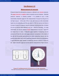
Well type manometer<br />
Sometimes a well type manometer is used. Schematic <strong>of</strong> a well type<br />
manometer is shown in Figure 64.<br />
Well type manometer<br />
, Measurement<br />
Fluid<br />
Diameter = D<br />
p<br />
h’<br />
p atm<br />
h<br />
Diameter = d<br />
,Manometer<br />
Liquid<br />
Figure 64 Schematic <strong>of</strong> a well type manometer<br />
The dashed line indicates the datum with reference to which the manometer<br />
height is measured. The advantage <strong>of</strong> the well type design is that relatively
Mechanical Measurements Pr<strong>of</strong>. S.P.Venkateshan<br />
<strong>Indian</strong> <strong>Institute</strong> <strong>of</strong> <strong>Technology</strong> <strong>Madras</strong><br />
large pressure differences may be measured with enough manometer liquid<br />
being available for doing so! We assume that the manometer liquid is<br />
incompressible and hence the following holds:<br />
hA ' = ha<br />
(65)<br />
This expression simply states that there is no change in the volume <strong>of</strong> the<br />
fluid and hence the mass. Here ‘A’ is the well cross section area given by<br />
2<br />
D<br />
A<br />
4<br />
π<br />
2<br />
d<br />
= while ‘a’ is the tube cross section area given by A<br />
4<br />
π<br />
= . Equation<br />
62 is recast for this case as<br />
p+ ρ g( h+ h') = p + ρ g( h+ h')<br />
(66)<br />
f a m<br />
Using Equation 65 in Equation 66, after some rearrangement we get<br />
⎛ a ⎞<br />
p − pa = ( ρm − ρf<br />
) g⎜1+ ⎟h<br />
(67)<br />
⎝ A ⎠<br />
If the area ratio a<br />
is very small compared to unity, we may use the<br />
A<br />
approximate formula that is identical with Equation 63.<br />
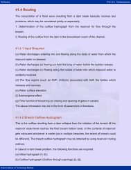
In case the measured pressure difference is small one may use an inclined<br />
well type manometer shown in Figure 65.
Mechanical Measurements Pr<strong>of</strong>. S.P.Venkateshan<br />
<strong>Indian</strong> <strong>Institute</strong> <strong>of</strong> <strong>Technology</strong> <strong>Madras</strong><br />
Well type manometer with<br />
inclined tube<br />
p<br />
Diameter = D<br />
h’<br />
R<br />
θ<br />
Diameter = d<br />
p atm<br />
Figure 65 Well type inclined tube manometer<br />
Incompressibility <strong>of</strong> the manometer liquid requires that Ah'= aL.<br />
The<br />
⎛ a ⎞<br />
manometer height is now given by Rsinθ + h'= R⎜sinθ<br />
+ ⎟.<br />
Equation 67 is<br />
⎝ A ⎠<br />
replaced by<br />
⎛ a ⎞<br />
p− pa = ( ρm − ρf ) g⎜sinθ + ⎟R<br />
⎝ A ⎠<br />
(68)<br />
It is clear that the inclination <strong>of</strong> the tube amplifies (recall the mechanical<br />
advantage <strong>of</strong> an inclined plane) the measured quantity and hence improves<br />
the precision <strong>of</strong> the measurement.
Mechanical Measurements Pr<strong>of</strong>. S.P.Venkateshan<br />
<strong>Indian</strong> <strong>Institute</strong> <strong>of</strong> <strong>Technology</strong> <strong>Madras</strong><br />
Example 23<br />
a) In an inclined tube manometer the manometer fluid is water at 20°C<br />
while the fluid whose pressure is to be measured is air. The angle <strong>of</strong><br />
the inclined tube is 20°. The well is a cylinder <strong>of</strong> diameter 0.05 m while<br />
the tube has a diameter <strong>of</strong> 0.001 m. The manometer reading is given<br />
to be 150 mm. Determine the pressure differential in mm water and<br />
Pa. What is the error in per cent if the density <strong>of</strong> air is neglected?<br />
b) Determine the error in the measured pressure differential if the<br />
reading <strong>of</strong> the manometer is within ±0.5 mm and the density <strong>of</strong> water<br />
has an error <strong>of</strong> ±0.2%. Assume that all other parameters have no<br />
errors in them. Neglect air density in this part <strong>of</strong> the question.<br />
Figure below indicates the numerical values specified in this problem.<br />
, air<br />
p<br />
Diameter = 5 cm<br />
h’<br />
Part a<br />
150 ± 0.5 mm<br />
20°<br />
p atm<br />
, water<br />
Diameter = 1 mm<br />
From the data shown in the Figure we calculate the area ratio as<br />
2 2<br />
a ⎛ d ⎞ ⎛ 0.001 ⎞ 1<br />
= ⎜ ⎟ = ⎜ ⎟ = = 0.0004<br />
A ⎝D⎠ ⎝ D0.05<br />
⎠ 2500<br />
Water density at the indicated temperature <strong>of</strong> 20°C is read <strong>of</strong>f a table <strong>of</strong><br />
properties as 997.6 kg/m 3 . The fluid is air at the same temperature and<br />
its density is obtained using ideal gas law. We use<br />
p Pa T K R J kgK<br />
5<br />
a = 1.013× 10 , = 273+ 20 = 297 , g =<br />
287 /
Mechanical Measurements Pr<strong>of</strong>. S.P.Venkateshan<br />
to get<br />
<strong>Indian</strong> <strong>Institute</strong> <strong>of</strong> <strong>Technology</strong> <strong>Madras</strong><br />
5<br />
pa<br />
1.013× 10<br />
ρ f = = = 1.205 kg / m<br />
RT 287× 297<br />
g<br />
The density <strong>of</strong> air has been calculated at the atmospheric temperature<br />
since it is at a pressure very close to it! The indicated pressure<br />
difference is then given by<br />
( )<br />
p− pa=<br />
997.6 − 1.205 × 9.81 × (sin 20 + 0.0004) × 0.15<br />
= 500.88 Pa<br />
This may be converted to mm <strong>of</strong> water column by dividing the above by<br />
mg ρ . Thus<br />
500.88<br />
p− pa= × 1000 = 51.2 mm water<br />
997.6× 9.8<br />
If we neglect the density <strong>of</strong> air in the above, we get<br />
p− pa=<br />
997.6× 9.81 × (sin 20 + 0.0004) × 0.15<br />
= 501.49 Pa<br />
The percentage error is given by<br />
501.49 − 500.88<br />
Δ p%<br />
= × 100 = 0.12<br />
500.88<br />
Part b<br />
The influence coefficients are now calculated. We have<br />
( )<br />
∂ p− pa ∂ρ f<br />
⎛ a ⎞<br />
= g⎜sinθ + ⎟R=<br />
9.87× ( sin 20 + 0.0004) × 0.15 = 0.5058<br />
⎝ A ⎠<br />
∂( p− pa) ⎛ a ⎞<br />
= ρ f g ⎜sinθ + ⎟=<br />
997.6× 9.87× ( sin 20 + 0.0004) = 3363.7<br />
∂R ⎝ A⎠<br />
The errors have been specified as<br />
0.2<br />
Δ R =± 0.5 mm =± 0.0005 m, Δ ρ f =± × 997.6 =± 1.995 kg / m<br />
100<br />
Use <strong>of</strong> error propagation formula yields the error in measured pressure<br />
as<br />
( ) ( )<br />
2 2<br />
Δ p =± 0.5058× 1.995 + 3363.7× 0.0005 =±<br />
1.96 Pa<br />
3<br />
3
Mechanical Measurements Pr<strong>of</strong>. S.P.Venkateshan<br />
<strong>Indian</strong> <strong>Institute</strong> <strong>of</strong> <strong>Technology</strong> <strong>Madras</strong><br />
Dynamic response <strong>of</strong> a U tube manometer<br />
In many applications the pressure difference to be measured may vary with<br />
time. The response time <strong>of</strong> the measuring instrument and the connecting<br />
tubes decide the response time. We make below a simple analysis <strong>of</strong> a U<br />
tube manometer subject to a step change in input.<br />
Diameter = d<br />
Total manometer<br />
liquid length =L<br />
Figure 66 Nomenclature for the transient analysis<br />
Because the manometer liquid is assumed to be incompressible the total<br />
length remains fixed at L. We assume that the manometer is initially in the<br />
equilibrium position and the pressure difference Δp is applied across it. The<br />
liquid column will move and will be as shown in Figure 66 at time t > 0. The<br />
forces that are acting on the length L <strong>of</strong> the manometer liquid are:<br />
2<br />
dh<br />
Fa mAL<br />
2<br />
dt<br />
1. Force due to acceleration <strong>of</strong> the liquid given by = ( ρ )<br />
2. Force supporting the change in h Fs= AΔ p<br />
3. Forces opposing the change:<br />
a. Weight <strong>of</strong> column <strong>of</strong> liquid = ( ρ )<br />
W Ah g<br />
Nomenclature:<br />
b. Fluid friction due to viscosity <strong>of</strong> the liquid.<br />
μ = Viscosity <strong>of</strong> manometer<br />
liquid<br />
h = Manometer height<br />
difference at time t<br />
Δp = Applied pressure<br />
difference across the<br />
manometer<br />
The viscous force opposing the motion is calculated based on the assumption<br />
<strong>of</strong> fully developed Hagen-Poiseuelle flow. The velocity <strong>of</strong> the liquid column is<br />
expected to be small and the laminar assumption is thus valid. We know from<br />
m
Mechanical Measurements Pr<strong>of</strong>. S.P.Venkateshan<br />
<strong>Indian</strong> <strong>Institute</strong> <strong>of</strong> <strong>Technology</strong> <strong>Madras</strong><br />
Fluid Mechanics that the pressure gradient and the mean velocity are related<br />
as<br />
u<br />
m<br />
dh d dp d Δp<br />
= =− =−<br />
dt 32μ dh 32μ<br />
L<br />
2 2<br />
f f<br />
where Δpf is the pressure drop due to friction. We define fluid resistance R as<br />
the ratio <strong>of</strong> frictional (viscous) pressure drop (potential difference) to the mass<br />
flow rate (current). We note that the mass flow rate is given by<br />
m= ρ Au<br />
m m<br />
2<br />
πd ⎛<br />
ρm 2<br />
d ⎞Δpf ⎛<br />
ρm<br />
4<br />
πd<br />
⎞Δpf<br />
=− ⎜ ⎟ =− ⎜ ⎟<br />
4 ⎝32μ ⎠ L ⎝128μ ⎠ L<br />
Δp<br />
f 128μL<br />
Hence the fluid resistance due to friction is given by R =− = . Note<br />
4<br />
mπρ d<br />
that the resistance involves only the geometric parameters and the liquid<br />
properties. The frictional force opposing the motion is thus given by Ff= mRA .<br />
Note that the mass flow rate is itself given by = m m = m<br />
2 dh<br />
frictional force opposing the motion is Ff = ρmA<br />
R .<br />
dt<br />
.<br />
dh<br />
m ρ Au ρ A . Hence the<br />
dt<br />
We may now apply Newton’s law as Fa = Fs −W − Ff<br />
. Introducing the<br />
expressions given above for the various terms, we get<br />
2<br />
dh 2 dh<br />
mAL A p 2<br />
mAghmRA ρ = Δ −ρ − ρ<br />
(69)<br />
dt dt<br />
We may rearrange this equation as<br />
2<br />
Ld h RAdh Δp<br />
h<br />
2<br />
ρm<br />
+ + = (70)<br />
g dt g dt g<br />
This is a second order ordinary differential equation that resembles the<br />
equation governing a spring mass dashpot system that is familiar to us from<br />
mechanics. The system is thus inherently a second order system. We define<br />
m
Mechanical Measurements Pr<strong>of</strong>. S.P.Venkateshan<br />
<strong>Indian</strong> <strong>Institute</strong> <strong>of</strong> <strong>Technology</strong> <strong>Madras</strong><br />
L<br />
a characteristic time given byτ<br />
= , damping ratio<br />
g<br />
Equation 70 in the standard form<br />
2<br />
2 dh dh Δp<br />
2 h<br />
2<br />
ρm<br />
RA<br />
ζ = to recast<br />
2gτ<br />
τ + ζτ + = (71)<br />
dt dt g<br />
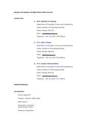
The above equation may easily be solved by standard methods. The<br />
response <strong>of</strong> the system is shown in Figure 67 for three different cases. The<br />
system is under-damped ifζ < 1,<br />
critically damped if ζ = 1 and over-damped<br />
ifζ > 1.<br />
When the system is under-damped the output shows oscillatory<br />
behaviour, the output shows an overshoot (a value more than the input) and<br />
the output settles down slowly. In the other two cases the response is<br />
monotonic, as shown in the figure. In the over-damped case the response<br />
grows slowly to eventually reach the full value.<br />
Non-Dimensional pressure,<br />
ρmgh/Δp<br />
1.4<br />
1.2<br />
1<br />
0.8<br />
0.6<br />
0.4<br />
0.2<br />
0<br />
Overdamped, ζ = 1.5<br />
Underdamped, ζ = 0.5<br />
Critically Damped, ζ = 1<br />
0 2 4 6 8 10<br />
Non-Dimensional time, t/τ<br />
Figure 67 Response <strong>of</strong> U tube manometer to step input
Mechanical Measurements Pr<strong>of</strong>. S.P.Venkateshan<br />
<strong>Indian</strong> <strong>Institute</strong> <strong>of</strong> <strong>Technology</strong> <strong>Madras</strong><br />
Example 24<br />
A U tube manometer uses mercury as the manometer liquid having a<br />
density <strong>of</strong><br />
kg m<br />
3<br />
ρ m = 13580 / and kinematic viscosity<br />
−7<br />
2<br />
<strong>of</strong>ν<br />
= 1.1× 10 m / s.<br />
The total length <strong>of</strong> the liquid is L = 0.6 m. The<br />
tube diameter is 2 mm. Determine the characteristic time and the<br />
damping ratio for this installation.<br />
Redo the above with water as the manometer liquid. The density and<br />
kinematic viscosity <strong>of</strong> water are 996 kg/m 3 and 10 -6 m 2 /s respectively.<br />
Part a<br />
2<br />
The given data is: L= 0.6 m, g = 9.81 m/ s and hence the characteristic<br />
time is<br />
L 0.6<br />
τ = = = 0.247 s<br />
g 9.81<br />
The liquid viscous resistance is calculated as<br />
−7<br />
128ν L 128× 1.1× 10 × 0.6 Pa<br />
R = = = 168067.6<br />
4 4<br />
πd π × 0.002 kg/ s<br />
The area <strong>of</strong> cross section <strong>of</strong> the tube is<br />
d ×<br />
A = = = 3.142× 10 m<br />
4 4<br />
2 2<br />
π π 0.002<br />
−6<br />
2<br />
The damping ratio is then calculated as<br />
−6<br />
RA 168067.6× 3.142× 10<br />
ζ = = = 0.109<br />
2gτ 2× 9.81× 0.247<br />
The system is under-damped
Mechanical Measurements Pr<strong>of</strong>. S.P.Venkateshan<br />
<strong>Indian</strong> <strong>Institute</strong> <strong>of</strong> <strong>Technology</strong> <strong>Madras</strong><br />
Part b<br />
When the manometer liquid is changed to water, only the resistance<br />
and the damping ratio change. The characteristic time remains the<br />
same at 0.247 s. The calculations may be repeated to get the<br />
following:<br />
−6<br />
128ν L 128× 10 × 0.6 Pa<br />
R = = = 1527887.5<br />
4 4<br />
πd π×<br />
0.002 kg/ s<br />
−6<br />
RA 1527887.5× 3.142× 10<br />
ζ = = = 0.9905<br />
2gτ 2× 9.81× 0.247<br />
Note that the system is very nearly critically damped.<br />
This example shows how liquid properties affect the dynamic response