Downloaded - Kodak
Downloaded - Kodak
Downloaded - Kodak

You also want an ePaper? Increase the reach of your titles
YUMPU automatically turns print PDFs into web optimized ePapers that Google loves.
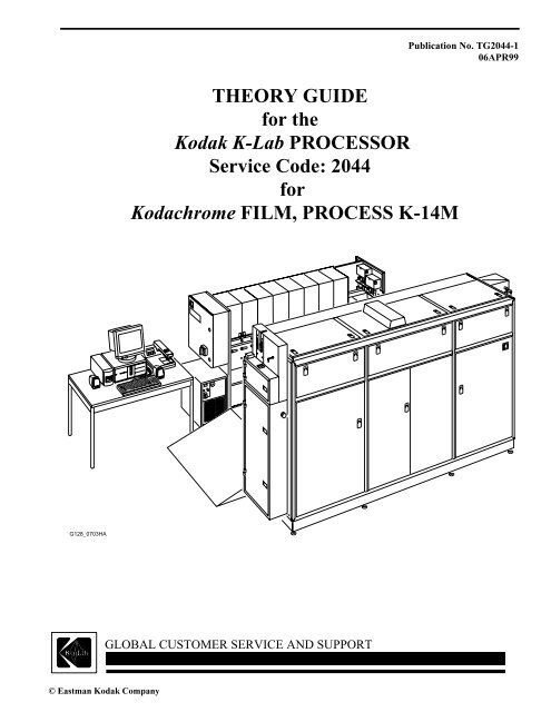
G128_0703HA<br />
GLOBAL CUSTOMER SERVICE AND SUPPORT<br />
© Eastman <strong>Kodak</strong> Company<br />
THEORY GUIDE<br />
for the<br />
<strong>Kodak</strong> K-Lab PROCESSOR<br />
Service Code: 2044<br />
for<br />
Kodachrome FILM, PROCESS K-14M<br />
Publication No. TG2044-1<br />
06APR99
PLEASE NOTE The information contained herein is based on the experience and knowledge relating to the<br />
subject matter gained by Eastman <strong>Kodak</strong> Company prior to publication.<br />
No patent license is granted by this information.<br />
Eastman <strong>Kodak</strong> Company reserves the right to change this information without notice, and<br />
makes no warranty, express or implied, with respect to this information. <strong>Kodak</strong> shall not be<br />
liable for any loss or damage, including consequential or special damages, resulting from any<br />
use of this information, even if loss or damage is caused by <strong>Kodak</strong>’s negligence or other fault.<br />
Table of Contents<br />
This equipment includes parts and assemblies sensitive to damage from electrostatic<br />
discharge. Use caution to prevent damage during all service procedures.<br />
Description Page<br />
Introduction . . . . . . . . . . . . . . . . . . . . . . . . . . . . . . . . . . . . . . . . . . . . . . . . . . . . . . . . . . . . 4<br />
Product Description. . . . . . . . . . . . . . . . . . . . . . . . . . . . . . . . . . . . . . . . . . . . . . . 4<br />
Product Safety . . . . . . . . . . . . . . . . . . . . . . . . . . . . . . . . . . . . . . . . . . . . . . . . . . . 4<br />
Components . . . . . . . . . . . . . . . . . . . . . . . . . . . . . . . . . . . . . . . . . . . . . . . . . . . . . . . . . . . . 5<br />
MAIN CONTROL COMPUTER (MCC) . . . . . . . . . . . . . . . . . . . . . . . . . . . . . 5<br />
System Communications . . . . . . . . . . . . . . . . . . . . . . . . . . . . . . . . . . . . . . . . . . 6<br />
PROCESSOR SINGLE BOARD COMPUTER (PSBC) . . . . . . . . . . . . . . . . . 7<br />
PROCESSOR . . . . . . . . . . . . . . . . . . . . . . . . . . . . . . . . . . . . . . . . . . . . . . . . . . . 8<br />
REPLENISHER RACK . . . . . . . . . . . . . . . . . . . . . . . . . . . . . . . . . . . . . . . . . . . 9<br />
CHILLER . . . . . . . . . . . . . . . . . . . . . . . . . . . . . . . . . . . . . . . . . . . . . . . . . . . . . . 11<br />
Film Transport and Drive System . . . . . . . . . . . . . . . . . . . . . . . . . . . . . . . . . . . . . . . . . . . 12<br />
Replenisher System . . . . . . . . . . . . . . . . . . . . . . . . . . . . . . . . . . . . . . . . . . . . . . . . . . . . . . 15<br />
Recirculation System . . . . . . . . . . . . . . . . . . . . . . . . . . . . . . . . . . . . . . . . . . . . . . . . . . . . . 16<br />
REEXPOSURE PRINTERS . . . . . . . . . . . . . . . . . . . . . . . . . . . . . . . . . . . . . . . . . . . . . . . 19<br />
Description . . . . . . . . . . . . . . . . . . . . . . . . . . . . . . . . . . . . . . . . . . . . . . . . . . . . . 19<br />
Red Reexposure Printing . . . . . . . . . . . . . . . . . . . . . . . . . . . . . . . . . . . . . . . . . . 19<br />
Blue Reexposure Printing . . . . . . . . . . . . . . . . . . . . . . . . . . . . . . . . . . . . . . . . . . 19<br />
Overprinting and Underprinting . . . . . . . . . . . . . . . . . . . . . . . . . . . . . . . . . . . . . 19<br />
Calibrating the REEXPOSURE PRINTERS . . . . . . . . . . . . . . . . . . . . . . . . . . . 19<br />
TEMPERATURE CONTROL BOARD . . . . . . . . . . . . . . . . . . . . . . . . . . . . . . . . . . . . . . 20<br />
Wash System . . . . . . . . . . . . . . . . . . . . . . . . . . . . . . . . . . . . . . . . . . . . . . . . . . . . . . . . . . . 23<br />
DRYER System . . . . . . . . . . . . . . . . . . . . . . . . . . . . . . . . . . . . . . . . . . . . . . . . . . . . . . . . . 24<br />
Processing Cycle . . . . . . . . . . . . . . . . . . . . . . . . . . . . . . . . . . . . . . . . . . . . . . . . . . . . . . . . 25<br />
Film Properties . . . . . . . . . . . . . . . . . . . . . . . . . . . . . . . . . . . . . . . . . . . . . . . . . . . . . . 25<br />
Film Exposure . . . . . . . . . . . . . . . . . . . . . . . . . . . . . . . . . . . . . . . . . . . . . . . . . . . . . . . 26<br />
Processing Steps . . . . . . . . . . . . . . . . . . . . . . . . . . . . . . . . . . . . . . . . . . . . . . . . . . . . . 27<br />
Backing Removal Solution . . . . . . . . . . . . . . . . . . . . . . . . . . . . . . . . . . . . . . . . . 27<br />
Backing Removal Wash . . . . . . . . . . . . . . . . . . . . . . . . . . . . . . . . . . . . . . . . . . . 27<br />
First Developer Solution . . . . . . . . . . . . . . . . . . . . . . . . . . . . . . . . . . . . . . . . . . . 27<br />
First Developer Wash . . . . . . . . . . . . . . . . . . . . . . . . . . . . . . . . . . . . . . . . . . . . . 27<br />
Red Reexposure Printing . . . . . . . . . . . . . . . . . . . . . . . . . . . . . . . . . . . . . . . . . . 27<br />
Cyan Developer Solution . . . . . . . . . . . . . . . . . . . . . . . . . . . . . . . . . . . . . . . . . . 28<br />
Cyan Developer Wash . . . . . . . . . . . . . . . . . . . . . . . . . . . . . . . . . . . . . . . . . . . . 28<br />
Blue Reexposure Printing . . . . . . . . . . . . . . . . . . . . . . . . . . . . . . . . . . . . . . . . . . 28<br />
Yellow Developer Solution. . . . . . . . . . . . . . . . . . . . . . . . . . . . . . . . . . . . . . . . . 29<br />
Yellow Developer Wash . . . . . . . . . . . . . . . . . . . . . . . . . . . . . . . . . . . . . . . . . . . 29<br />
Magenta Developer Solution . . . . . . . . . . . . . . . . . . . . . . . . . . . . . . . . . . . . . . . 29<br />
Magenta Developer Wash. . . . . . . . . . . . . . . . . . . . . . . . . . . . . . . . . . . . . . . . . . 29<br />
2 06APR99 – TG2044-1
Conditioner . . . . . . . . . . . . . . . . . . . . . . . . . . . . . . . . . . . . . . . . . . . . . . . . . . . . . 29<br />
Bleach . . . . . . . . . . . . . . . . . . . . . . . . . . . . . . . . . . . . . . . . . . . . . . . . . . . . . . . . . 30<br />
Fixer. . . . . . . . . . . . . . . . . . . . . . . . . . . . . . . . . . . . . . . . . . . . . . . . . . . . . . . . . . . 30<br />
Final Wash. . . . . . . . . . . . . . . . . . . . . . . . . . . . . . . . . . . . . . . . . . . . . . . . . . . . . . 30<br />
Final Rinse. . . . . . . . . . . . . . . . . . . . . . . . . . . . . . . . . . . . . . . . . . . . . . . . . . . . . . 30<br />
Mechanical Specifications . . . . . . . . . . . . . . . . . . . . . . . . . . . . . . . . . . . . . . . . . 31<br />
Process Control . . . . . . . . . . . . . . . . . . . . . . . . . . . . . . . . . . . . . . . . . . . . . . . . . . . . . . . . . . 32<br />
Introduction . . . . . . . . . . . . . . . . . . . . . . . . . . . . . . . . . . . . . . . . . . . . . . . . . . . . . 32<br />
Making Density Measurements. . . . . . . . . . . . . . . . . . . . . . . . . . . . . . . . . . . . . . 32<br />
Control Strip Exposure . . . . . . . . . . . . . . . . . . . . . . . . . . . . . . . . . . . . . . . . . . . . 32<br />
Control Strip Film . . . . . . . . . . . . . . . . . . . . . . . . . . . . . . . . . . . . . . . . . . . . . . . . 33<br />
Control Strip Stability . . . . . . . . . . . . . . . . . . . . . . . . . . . . . . . . . . . . . . . . . . . . . 33<br />
Standard Aim Values. . . . . . . . . . . . . . . . . . . . . . . . . . . . . . . . . . . . . . . . . . . . . . 33<br />
Densitometer Correlation Strips . . . . . . . . . . . . . . . . . . . . . . . . . . . . . . . . . . . . . 33<br />
Using 35 mm x 100 ft Roll Film Control Strips . . . . . . . . . . . . . . . . . . . . . . . . . 33<br />
Storing and Handling Control Strips . . . . . . . . . . . . . . . . . . . . . . . . . . . . . . . . . . 34<br />
Processing and Evaluating Control Strips . . . . . . . . . . . . . . . . . . . . . . . . . . . . . 35<br />
Frequency of Processing Control Strips . . . . . . . . . . . . . . . . . . . . . . . . . . . 35<br />
Processing Monitoring Procedure . . . . . . . . . . . . . . . . . . . . . . . . . . . . . . . . 35<br />
Evaluating the Processed Control Strips . . . . . . . . . . . . . . . . . . . . . . . . . . . 35<br />
Sequence of Operation . . . . . . . . . . . . . . . . . . . . . . . . . . . . . . . . . . . . . . . . . . . . . . . . . . . . 37<br />
Energizing the PROCESSOR . . . . . . . . . . . . . . . . . . . . . . . . . . . . . . . . . . . . . . . 37<br />
Entering Sleep Mode . . . . . . . . . . . . . . . . . . . . . . . . . . . . . . . . . . . . . . . . . . . . . . 38<br />
Operator Actions . . . . . . . . . . . . . . . . . . . . . . . . . . . . . . . . . . . . . . . . . . . . . 38<br />
Entering Standby Mode. . . . . . . . . . . . . . . . . . . . . . . . . . . . . . . . . . . . . . . . . . . . 39<br />
Entering Processing Mode. . . . . . . . . . . . . . . . . . . . . . . . . . . . . . . . . . . . . . . . . . 39<br />
Operator Actions . . . . . . . . . . . . . . . . . . . . . . . . . . . . . . . . . . . . . . . . . . . . . 39<br />
Entering Power Off Mode . . . . . . . . . . . . . . . . . . . . . . . . . . . . . . . . . . . . . . . . . . 39<br />
Operator Actions . . . . . . . . . . . . . . . . . . . . . . . . . . . . . . . . . . . . . . . . . . . . . 39<br />
Glossary of Terms, Acronyms, and Abbreviations . . . . . . . . . . . . . . . . . . . . . . . . . . . . . . 40<br />
TG2044-1 – 06APR99 3
THEORY GUIDES<br />
Section 1: Introduction<br />
Product Description<br />
Product Safety<br />
The <strong>Kodak</strong> K-Lab PROCESSOR for Kodachrome FILM, PROCESS K-14M, processes 35 mm<br />
Kodachrome FILM using specially packaged chemicals.<br />
The PROCESSOR is a white-light, continuous magazine feed, floor-standing machine, with 5 major<br />
components:<br />
• MAIN CONTROL COMPUTER (MCC)<br />
• PROCESSOR<br />
• REPLENISHER RACK<br />
• CHILLER<br />
• SPLICER (stand-alone, optional)<br />
• FILLING STATION<br />
A FEED MAGAZINE of exposed film is assembled at the SPLICER. After it is spliced onto a leader,<br />
the FILM MAGAZINE contents are transported into the FEED ELEVATOR. Then the film transports<br />
through a series of tanks containing the film processing solutions. After development, the film goes<br />
through the DRYING CHAMBER and onto a REEL in the take-off section of the PROCESSOR. The<br />
film is ready for mounting or finishing.<br />
The <strong>Kodak</strong> K-Lab PROCESSOR for Kodachrome FILM, PROCESS K-14M provides:<br />
• DEVELOPER TANKS that hold 17.5 - 18.5 liters of developer solution<br />
• Air process to regenerate the bleach<br />
• DEVELOPER TANKS with a tube-within-a-tube-style construction, with the inner-tube easily<br />
removed for service<br />
• MAGAZINE SHOE compatible with the 400 ft Source Two, Inc. MAGAZINE<br />
• High-velocity impingement agitation in the developers<br />
• "Demand" system, with a center pacer, DRIVE design:<br />
1. Specification: 2% of set transport speed<br />
2. Film tension: (0.5 - 1.0 lbs)<br />
• CHILLER system that achieves temperature specifications within the DEVELOPER TANKS<br />
• INTELLIFAUCETS that mix house water to provide 29.5 - 38°C (85 - 100°F ) water<br />
• System of SWITCHES that monitor, alarm, and maintain the process<br />
• Built-in push processing at three levels: 1 ⁄2 , 1 1 ⁄3 , and +2 stops<br />
As a safety precaution, whenever the PROCESSOR is put in the Standby Mode, the HEATERS remain<br />
de-energized until the “Heater Control” command is enabled by the CPU. The “Heater Control”<br />
command enables the HEATER outputs unless a flow alarm condition occurs.<br />
4 06APR99 – TG2044-1
Section 2: Components<br />
MAIN CONTROL COMPUTER (MCC)<br />
28_4902HCB<br />
28_4902HC<br />
MAIN CONTROL<br />
COMPUTER<br />
Components<br />
The MAIN CONTROL COMPUTER (MCC) is the “brain” of the PROCESSOR. It controls all of the components<br />
and is the only interface for the operator to view the status of the PROCESSOR. The MCC can be separated from the<br />
PROCESSOR by up to 50 ft. The MCC is a commercially available IBM-compatible computer, that has been<br />
modified, running a Microsoft Windows software-based machine-control program. Use the MCC to:<br />
• Energize and de-energize the PROCESSOR<br />
• Monitor all electronic and mechanical subsystems through a network of SENSORS<br />
• Gather and analyze chemical, mechanical, and sensitometric data acquired during film processing<br />
• Respond to emergencies such as film breaks<br />
An UNINTERRUPTIBLE POWER SUPPLY (UPS) allows the MCC to continue operating in the event of a power<br />
failure.<br />
TG2044-1 – 06APR99 5
THEORY GUIDES<br />
System Communications<br />
TEMPERATURE<br />
CONTROLLER<br />
COMPUTER<br />
DB9F<br />
G128_1902DC<br />
PROCESSOR ELECTRICAL CABINET<br />
REEXPOSURE<br />
PRINTERS<br />
COMPUTER<br />
PROCESSOR<br />
COMPUTER<br />
DB9M<br />
10-PIN HEADER<br />
COM1-J4<br />
REPLENISHER RACK<br />
ELECTRICAL CABINET<br />
10-PIN HEADER<br />
COM1 - J1<br />
10-PIN HEADER<br />
COM2 - J2<br />
3 COND<br />
3 COND<br />
3 COND<br />
3 COND<br />
3 COND<br />
3 COND, UNSHIELDED,<br />
50 ft. LENGTH MAX.<br />
OVERALL FOIL/<br />
BRAID SHIELD<br />
20 COND<br />
50 ft. LENGTH<br />
MAX.<br />
10-PIN HEADER<br />
COM1 - J1<br />
DB9M - COM1<br />
DENSITOMETER<br />
The HOST COMPUTER communicates with the PROCESSING COMPUTER and the REPLENISHER<br />
COMPUTER through serial communications. The HOST COMPUTER and REPLENISHER COMPUTER can be<br />
separated from the PROCESSOR by up to 50 ft.<br />
6 06APR99 – TG2044-1<br />
DB78M<br />
REPLENISHER COMPUTER<br />
DB78F<br />
HOST<br />
COMPUTER
PROCESSOR SINGLE BOARD COMPUTER (PSBC)<br />
G128_1703CC<br />
PROCESSOR<br />
SINGLE BOARD<br />
COMPUTER<br />
Components<br />
The PROCESSOR SINGLE BOARD COMPUTER<br />
(PSBC) is located inside the PROCESSOR Electrical<br />
Cabinet.<br />
The PSBC monitors and controls the individual<br />
SENSORS and components located within the<br />
PROCESSOR and reports their status to the MAIN<br />
CONTROL PROGRAM (MCP). It also alerts the MCP<br />
when a SENSOR or component malfunctions or does<br />
not respond as anticipated.<br />
The PSBC receives commands for data and control<br />
from the main control program through a serial<br />
connection between the PROCESSOR and the MAIN<br />
CONTROL COMPUTER. The PSBC passes the<br />
appropriate commands to the REPLENISHER RACK<br />
SINGLE BOARD COMPUTER (RSBC) through a<br />
serial connection.<br />
The PSBC communicates with 3 SOLID STATE<br />
RELAY BOARDS which accept input from various<br />
SENSORS, thereby allowing the PSBC to control<br />
various PUMPS and SOLENOIDS.<br />
The PSBC is a small IBM-compatible, SINGLE-<br />
BOARD COMPUTER with Microsoft MS-DOS<br />
programmed into a ROM CHIP. The program it runs is<br />
contained on another CHIP on the BOARD and<br />
executes automatically when the RSBC energizes.<br />
The PSCB has 5 primary functions:<br />
1. Energizes and de-energizes the PROCESSOR<br />
components for Sleep, Standby, and Processing<br />
Modes<br />
2. Monitors the operating condition of each<br />
component in the PROCESSOR and sounds an<br />
alarm if it detects a malfunction<br />
3. Initiates the command for chemical replenisher<br />
4. Monitors the condition of all the components in<br />
both the PROCESSOR and the REPLENISHER<br />
RACK and provides the operator with status<br />
information<br />
5. Monitors the serial port for the REPLENISHER<br />
COMPUTER for messages and requests for<br />
chemical replenisher<br />
TG2044-1 – 06APR99 7
THEORY GUIDES<br />
PROCESSOR<br />
The PROCESSOR consists of 7 different wet sections:<br />
1. Rem-jet<br />
2. First developer and wash<br />
3. Cyan developer and wash<br />
4. Yellow developer and wash<br />
5. Magenta developer and wash<br />
6. Conditioner and bleach<br />
7. Fix, wash, and final rinse<br />
The PROCESSOR also includes a DRYER tank that is similar in construction to the wet section tanks. The<br />
temperature in the DRYER tank is controlled to be within the range of 41°± 3°C (105° ± 5°F).<br />
The PROCESSOR has the following 4 modes of operation:<br />
• Power Off Mode<br />
During this mode, the MAIN CONTROL COMPUTER and PROCESSOR are inactive. The PROCESSOR<br />
is in this mode during installation or when all chemicals have been removed for a long shutdown, such as<br />
over weekends.<br />
• Sleep Mode<br />
During this mode, only the MAIN CONTROL COMPUTER (MCC) and the components in the<br />
PROCESSOR ELECTRICAL CABINET are energized. All mechanical components of the PROCESSOR<br />
are de-energized.<br />
It takes approximately 5 minutes to reach Sleep Mode after being in Power Off Mode.<br />
• Standby Mode<br />
This mode is used as a system check when you first energize the PROCESSOR and between batches of film<br />
runs. During this mode, all components of the PROCESSOR are energized and monitored and all chemicals<br />
are maintained at their setpoint temperatures.<br />
It takes approximately 30 - 45 minutes for the PROCESSOR to reach Standby Mode after being in Sleep<br />
Mode.<br />
• Processing Mode<br />
During this mode, the PROCESSOR actively processes film, and all chemicals are at a stable temperature.<br />
The PROCESSOR should be set back to Standby Mode if no additional batches are waiting for processing.<br />
You may select to process film or a control/scratch film strip.<br />
It takes approximately 2 minutes for the PROCESSOR to reach Processing Mode after being in Standby<br />
Mode.<br />
8 06APR99 – TG2044-1
REPLENISHER RACK<br />
G128_1903DCA<br />
G128_1903DC<br />
REPLENISHER RACK<br />
Components<br />
The REPLENISHER RACK is a module connected to the PROCESSOR with plastic tubing for automatic chemical<br />
replenisher. The REPLENISHER RACK ASSEMBLY consists of:<br />
• REPLENISHER RACK COMPUTER<br />
• WASH WATER INTELLIFAUCETS<br />
• REPLENISHER PUMPS<br />
• RACK FRAME ASSEMBLY for holding Bag-In-Boxes (BIBs)<br />
• 5 STORAGE TANKS<br />
• All plumbing and electrical connections necessary to deliver replenisher and wash water to the chemical TANKS<br />
in the PROCESSOR<br />
• 2 regulated air lines:<br />
– AIR SQUEEGEE at the red LAMP<br />
– AIR SQUEEGEE at the DRYER and supplies bleach aeration<br />
TG2044-1 – 06APR99 9
THEORY GUIDES<br />
The REPLENISHER RACK SINGLE BOARD COMPUTER (RRSBC), located in the ELECTRICAL CABINET<br />
of the REPLENISHER RACK, controls all the electronics.<br />
Physically, the RSBC is identical to the PSBC. The RSBC, however, runs a different program that monitors the<br />
SENSORS and PUMPS in the REPLENISHER RACK.<br />
When a malfunction occurs in the REPLENISHER RACK, or the PSBC requests the status of a SENSOR, the RSBC<br />
transmits its data to the PSBC through a serial port connection.<br />
The RSBC:<br />
• Monitors the serial port to the PROCESSOR COMPUTER for commands and data<br />
• Energizes and de-energizes the components in the REPLENISHER RACK for Sleep, Standby, and Processing<br />
Modes<br />
• Calculates the correct energize and de-energize times for the REPLENISHER PUMPS COMPUTER<br />
10 06APR99 – TG2044-1
CHILLER<br />
CHILLER<br />
(includes PUMP<br />
and RESEVOIR)<br />
G128_0422GCA<br />
G128_0422GC<br />
Components<br />
Caution<br />
De-energize the CHILLER before removing any HOSES.<br />
The CHILLER SYSTEM provides a constant thermal load to work against the HEATERS. This increases the<br />
stability of the developer solutions. The CHILLER cools the water to 24°C (75°F) and recirculates this water through<br />
metal CHILLER TUBES in the bottom of the DEVELOPER TANKS. This is a closed-loop system with a small<br />
reservoir. Any time the CHILLER energizes, water PUMPS through the system. The PUMP drains the CHILLER in<br />
a very short time. When reassembling the CHILLER SYSTEM during servicing, check that the RESERVOIR is<br />
filled correctly.<br />
The CHILLER delivers 25°C (77°F) water to cool the 4 developers in the PROCESSOR. The circulation of the<br />
chilled water helps the TEMPERATURE CONTROLLER maintain the setpoint temperatures of the processing<br />
solutions.<br />
TG2044-1 – 06APR99 11
THEORY GUIDES<br />
Section 3: Film Transport and Drive System<br />
ENTRANCE<br />
ROLLER (CLUTCH)<br />
FILM<br />
SENSOR<br />
G128_0423HCA<br />
G128_0423HC<br />
The SUPPLY DRIVE MOTOR pulls either the film or leader out of the CASSETTE into the SPLICE CABINET.<br />
The UPPER and LOWER SWITCHES in the ELEVATOR CABINET energize and de-energize the MOTOR. The<br />
excess film is taken up in the ELEVATOR.<br />
A CLUTCH on the ENTRANCE ROLLER, between the ELEVATOR and the REM JET ASSEMBLY, prevents the<br />
wet film from going back into the ELEVATOR. When there is tension on the film, the ROLLERS on the DEMAND<br />
DRIVE RACK contact the DEMAND DRIVE ROLLER to RELIEVE THE TENSION.<br />
The film is pulled from the ELEVATOR through the cyan developer by the CENTER PACER DRIVE. The TAKE-<br />
OFF PACER DRIVE pulls the film through the rest of the PROCESSOR. The film is then taken up by either TAKE-<br />
UP MOTOR that the TAKE-OFF ELEVATOR controls.There are 2 AIR SQUEEGEES in the PROCESSOR. The<br />
first is located before the red REEXPOSURE PRINTER. The second is located at the DRYER entrance. The air<br />
pressure at the REGULATOR, and the gaps between the BLADES of the AIR SQUEEGEE must be correct or excess<br />
tension on the leader material may cause the film to break.<br />
12 06APR99 – TG2044-1
DEMAND DRIVE<br />
ROLLER<br />
SPLICE CABINET<br />
SUPPLY DRIVE MOTOR<br />
CASSETTE (not shown)<br />
ELEVATOR<br />
ENTRANCE<br />
ROLLER<br />
G128_4015DCA<br />
WITH FILM TENSION WITHOUT FILM TENSION<br />
REM JET AY<br />
7 DEMAND DRIVES<br />
AIR SQUEEGEE<br />
G128_4015DC UPPER and LOWER SWITCHES (not shown)<br />
1ST PACER<br />
DRIVE AIR SQUEEGEE<br />
Film Transport and Drive System<br />
TAKE-OFF<br />
PACER DRIVE<br />
TAKE-OFF<br />
MOTORS<br />
TG2044-1 – 06APR99 13
THEORY GUIDES<br />
CYAN DEVELOPER and WASH<br />
FIRST DEVELOPER and WASH<br />
FILM<br />
MAGAZINE<br />
SPLICE<br />
CABINET<br />
FEED<br />
CABINET and<br />
ELEVATOR<br />
G128_4003HCA<br />
G128_4003HC<br />
BLUE PRINTER<br />
RED PRINTER<br />
TANK 1<br />
REM JET<br />
DIP and RINSE<br />
TANK 2<br />
TANK 3 TANK 4<br />
YELLOW DEVELOPER and WASH<br />
MAGENTA DEVELOPER and WASH<br />
TANK 5 TANK 6<br />
CONDITIONER and BLEACH<br />
FIXER and FINAL RINSE<br />
14 06APR99 – TG2044-1<br />
TANK 7<br />
DRYER<br />
TAKE-OFF<br />
ASSEMBLY<br />
TAKE-OFF<br />
REELS
Section 4: Replenisher System<br />
G128_4306HCA<br />
G128_4306HC<br />
PROCESSOR<br />
TANK<br />
VALVE<br />
CHECK<br />
VALVE<br />
3 WAY<br />
VALVE<br />
CAL<br />
BIB<br />
FLOW<br />
MONITOR<br />
Replenisher System<br />
The REPLENISHER SYSTEM maintains chemistry at the correct strength in relation to the film that runs through<br />
the PROCESSOR. A single-board computer in the REPLENISHER RACK determines replenisher rates. Depending<br />
on the amount of film and film type, the appropriate REPLENISHER PUMP energizes. The PUMP pumps the<br />
REPLENISHER chemistry from the BIB through the PUMP, through a FLOW MONITOR, through 3-WAY<br />
VALVE and QUICK DISCONNECT, through a series of CHECK VALVES and HOSES, and into the bottom of the<br />
TANK. The FILM DETECTOR, at the entrance of the wet section, detects the amount of film. The FILM<br />
DETECTOR sends a signal to the SBC as to whether the PROCESSOR is transporting film or leader. When the film<br />
is spliced, the type of film is detected. This data is input into the computer at the start of a film batch.<br />
TG2044-1 – 06APR99 15<br />
RUN<br />
PUMP<br />
QUICK<br />
DISCONNECT<br />
CHECK<br />
VALVE
THEORY GUIDES<br />
Section 5: Recirculation System<br />
from INTELIFAUCET WATER INLET<br />
OVERFLOW<br />
TO DRAIN<br />
TO<br />
DRAIN<br />
G128_5702EA<br />
WASH<br />
DEVELOPER<br />
TOP VIEW<br />
FIRST<br />
DEVELOPER<br />
FRONT VIEW<br />
BOTTOM VIEW<br />
OVERFLOW<br />
TO DRAIN<br />
HEAT<br />
EXCHANGER<br />
WASH<br />
DEVELOPER<br />
REPLENISHER<br />
FILTER<br />
PRESSURE<br />
SWITCH<br />
RECIRCULATION<br />
PUMP<br />
PUMP<br />
16 06APR99 – TG2044-1
Recirculation System<br />
The recirculation system contains:<br />
• RECIRCULATION PUMP<br />
• PRESSURE SWITCH<br />
• FILTER POT<br />
• HEAT EXCHANGER<br />
• IMPINGEMENT TUBES in the DEVELOPER TANKS<br />
The PUMP operates when the PROCESSOR is in the standby and processing modes. The PRESSURE SWITCH deenergizes<br />
the HEATER in the HEAT EXCHANGER if the pressure is too low. A BYPASS HOSE and SHUT OFF<br />
VALVES on each side of the FILTER POTS allow the FILTER to be changed when the system operates.<br />
TG2044-1 – 06APR99 17
THEORY GUIDES<br />
18 06APR99 – TG2044-1
Section 6: REEXPOSURE PRINTERS<br />
Description<br />
REEXPOSURE PRINTERS<br />
The PROCESSOR requires 2 REEXPOSURE PRINTER modules:<br />
• one filtered to reexpose the blue layer on the film<br />
• one filtered to reexpose the red layer on the film<br />
Each REEXPOSURE PRINTER module consists of a LAMP and a LAMPHOUSE that deliver filtered<br />
light to an exposure plane positioned to expose the moving film web. A PHOTO DETECTOR collects<br />
the filtered exposure energy data as the sample is exposed.<br />
An embedded computer controls the 2 reexposure printers. The computer measures the exposure<br />
energy with the PHOTO DETECTORS and controls the exposure energy (brightness of the LAMP) by<br />
adjusting the voltages of the LAMPS.<br />
Red Reexposure Printing<br />
The red reexposure printing exposes all of the remaining silver halide in the red sensitive (bottom)<br />
emulsion layer so that the silver halide develops completely in the cyan developer solution. During this<br />
step, exposure of any remaining silver halide in the blue- and green-sensitive layers must be avoided<br />
to prevent unwanted cyan dye development in these layers. This selective reexposure is obtained by<br />
printing through the base side of the film, using a properly selected red glass filter in the light beam.<br />
The green and blue sensitive emulsion layers have no intentional sensitivity to red light and should,<br />
therefore, remain unaffected by the red-light exposure. However, some green-sensitive emulsion layers<br />
do have a slight, but significant, red-sensitivity, making accurate control of the red printing intensity<br />
necessary.<br />
Blue Reexposure Printing<br />
The blue reexposure printing exposes all the remaining silver halide in the blue-sensitive emulsion<br />
layer so that the silver halide develops completely in the yellow developer solution. During this step,<br />
exposure of the remaining silver halide in the green- sensitive layer must be avoided to prevent<br />
unwanted yellow dye development in the green-sensitive layer. This selective reexposure is obtained<br />
by printing through the emulsion surface of the film, using a properly selected blue glass filter in the<br />
light beam. The yellow filter layer between the blue- and green-sensitive layers limits passage of the<br />
blue light from the emulsion side. However, the filter layer does not protect the green-sensitive layer<br />
from any stray blue printing light that may strike the base of the film.<br />
Overprinting and Underprinting<br />
Once an optimum printing intensity is established for each PRINTER, the process should be controlled<br />
carefully to avoid either overprinting or underprinting.<br />
Overprinting can result in unwanted reexposure and subsequent yellow development of silver halide in<br />
the green-sensitive (magenta) layer. Underprinting leaves some of the silver halide in the yellow layer<br />
unexposed and subject to chemical reexposure and development in the magenta developer. Either<br />
situation can cause some degradation in quality.<br />
Calibrating the REEXPOSURE PRINTERS<br />
When the PROCESSOR energizes, the REEXPOSURE PRINTERS automatically perform a LAMP<br />
calibration sequence. During the sequence, exposure energy is monitored while the LAMPS cycle from<br />
the lowest to the highest voltages. The data collected is put into a table and used to find voltage levels<br />
needed to obtain exposure levels requested by the MCP.<br />
The calibration sequence takes several minutes to perform. During the sequence all messages from the<br />
SERIAL PORT are ignored. When the sequence completes, both LAMPS are set to a nominal value<br />
and a message is sent to the HOST COMPUTER that the REEXPOSURE PRINTERS are ready.<br />
TG2044-1 – 06APR99 19
THEORY GUIDES<br />
Section 7: TEMPERATURE CONTROL BOARD<br />
G128_1702HCA<br />
G128_1702HC<br />
9-PIN<br />
CONNECTOR<br />
5<br />
1<br />
RS232<br />
PWR<br />
PWR<br />
120 \ 240 V AC<br />
50 / 60 Hz<br />
G<br />
IN4 IN3 IN2<br />
GROUND<br />
IN1<br />
NORMAL<br />
+5E V DC<br />
+5V DC<br />
+15A V DC<br />
-5A V DC<br />
5-PIN CONNECTOR<br />
W<br />
R CH8<br />
R<br />
W<br />
R CH7<br />
R<br />
W<br />
R CH6<br />
R<br />
W<br />
R CH5<br />
R<br />
W<br />
R CH4<br />
R<br />
W<br />
R CH3<br />
R<br />
W<br />
R CH2<br />
R<br />
W<br />
R CH1<br />
R<br />
3 WIRE RTD<br />
(TYPICAL 8 PLACES)<br />
The TEMPERATURE CONTROL BOARD is mounted in the ELECTRICAL CABINET of the<br />
PROCESSOR. The unit is a MICROPROCESSOR-based CONTROLLER that can control 8 different<br />
temperatures simultaneously.<br />
The unit consists of 2 CIRCUIT BOARDS. The main CIRCUIT BOARD contains:<br />
• 3 POWER SUPPLIES<br />
• digital MICROPROCESSOR CIRCUITS<br />
• 8 analog input conditioning circuitry<br />
The 3 POWER SUPPLIES generate the necessary DC voltage to control the PROCESSOR. Separate<br />
POWER SUPPLIES generate power for the analog circuitry and the digital circuitry. The third<br />
POWER SUPPLY generates power for the RS232 serial interface and the SOLID STATE RELAY<br />
DRIVERS. By using the separate POWER SUPPLY, electrical noise and possible static damage can<br />
be kept to a minimum.<br />
The digital circuitry consists of:<br />
• Programmable Read Only Memory (PROM)<br />
• Analog-to-digital CONVERTERS<br />
• Light Emitting Diode (LED)<br />
20 06APR99 – TG2044-1<br />
WHITE<br />
RED<br />
RED<br />
PE BL3-3 PIN
G128_1701HCA<br />
G128_1701HC<br />
TEMPERATURE CONTROL BOARD<br />
The analog circuitry consists of:<br />
• RESISTANCE TEMPERATURE DETECTOR (RTD), which is a component that varies the<br />
voltage it outputs depending on the temperature to which it is exposed<br />
• INSTRUMENTATION AMPLIFIER<br />
– converts the low level signal from the RTD to a usable level, which is converted to a digital<br />
value by the analog-to-digital CONVERTERS<br />
– the converted digital value can then be read as a temperature by the MICROPROCESSOR<br />
+17<br />
FIX<br />
SSR #6<br />
HEAT<br />
SSR #5<br />
HEAT<br />
BLEACH<br />
SPARE<br />
SSR #7<br />
HEAT<br />
J3<br />
SSR #4<br />
HEAT<br />
MAGENTA<br />
DRYER<br />
SSR #8<br />
HEAT<br />
1<br />
SSR #3<br />
HEAT<br />
YELLOW<br />
SSR LED (10)<br />
SSR #9<br />
SSR #10<br />
HEAT<br />
COOL<br />
BOOST BOOST<br />
SSR #2<br />
HEAT<br />
CYAN<br />
SSR #1<br />
HEAT<br />
1ST DEVELOPER<br />
RED STRIPE<br />
The second BOARD, which is attached to the MAIN BOARD by a RIBBON CABLE, contains drive<br />
circuitry to energize the SOLID STATE RELAYS (SSRs) that control:<br />
• HEATERS<br />
• SUPER HEATER<br />
• SUPER CHILLER<br />
The BOARD can control 10 SSRs, but only 9 SSRs are used. The first 7 SSRs control the HEATERS<br />
for each of the chemical TANKS in the PROCESSOR. The other 2 SSRs control the SUPER HEATER<br />
and SUPER CHILLER.<br />
TG2044-1 – 06APR99 21<br />
J1
THEORY GUIDES<br />
The relay board channels for the TEMPERATURE CONTROLLER are assigned as outlined below:<br />
Solution or<br />
Channel<br />
Component<br />
1 First Developer<br />
2 Cyan Developer<br />
3 Yellow Developer<br />
4 Magenta Developer<br />
5 Bleach<br />
6 Fixer<br />
7 unused<br />
8 DRYER<br />
9 HEATER BOOST<br />
10 CHILLER BOOST<br />
The RS232 communication link controls the operation of the MICROPROCESSOR. The user can:<br />
• Program all variables, setpoints, and alarms through the RS232 communication link.<br />
• Check the status and obtain alarm information through the RS232 PORT.<br />
22 06APR99 – TG2044-1
Section 8: Wash System<br />
from INTELIFAUCET WATER INLET<br />
SPRAY<br />
HEAD<br />
G128_4500DCA<br />
G128_4500DC<br />
WASH<br />
CHEMICAL<br />
SOLUTION<br />
TOP VIEW<br />
OVERFLOW<br />
TO DRAIN<br />
FLOW VALVES<br />
Wash System<br />
RECIRCULATION<br />
PUMP<br />
from bottom<br />
of TANK<br />
The recirculation system consists of:<br />
• RECIRCULATION PUMP<br />
• FLOW VALVES<br />
• SPRAY HEADS<br />
Another part of this system is a FLOW CONTROL FITTING on the SUPPLY WATER MANIFOLD and an<br />
OVERFLOW FITTING. Fresh water is supplied at the top of the WASH TANK. Wash water is drawn off the bottom<br />
of the TANK, through the PUMP, through the FLOW VALVES that regulate the flow through the SPRAY HEADS.<br />
Excess water goes through the OVERFLOW FITTING and through a HOSE to the WASTE MANIFOLD.<br />
TG2044-1 – 06APR99 23
THEORY GUIDES<br />
Section 9: DRYER System<br />
G128_0006HCA<br />
G128_0006HC<br />
DRYER TANK<br />
RESISTOR THERMAL DEVICE<br />
PRESSURE SWITCH<br />
HEATER<br />
BLOWER<br />
PLENUM<br />
The DRYER system consists of:<br />
• BLOWER<br />
• HEATER<br />
• PRESSURE SWITCH<br />
• PLENUM<br />
• RESISTOR THERMAL DEVICE (mounted in the DRYER TANK)<br />
The TEMPERATURE CONTROLLER and the No. 8 SSR on the SOLID STATE RELAY BOARD control the<br />
temperature. As a safety precaution, the HEATER does not operate unless the PRESSURE SWITCH senses air flow<br />
from the BLOWER.<br />
24 06APR99 – TG2044-1
Section 10: Processing Cycle<br />
Film Properties<br />
BLUE SENSITIVE<br />
YELLOW FILTER<br />
BLUE-GREEN SENSITIVE<br />
BLUE-RED SENSITIVE<br />
ACETATE<br />
SUPPORT<br />
ANTIHALATION BACKING<br />
G128_0001DC<br />
CYAN<br />
DEVELOPER<br />
FORMS CYAN DYE<br />
1 EXPOSED SILVER HALIDE<br />
+<br />
DEVELOPER<br />
SILVER<br />
+<br />
2 OXIDIZED DEVELOPER<br />
+<br />
COUPLER<br />
CYAN DYE<br />
RAW STOCK<br />
BLUE<br />
RE-EXPOSURE<br />
BLUE LIGHT<br />
CAMERA<br />
EXPOSURE<br />
BLACK WHITE<br />
LATENT IMAGE FORMS<br />
ON EXPOSED GRAINS<br />
PROCESS<br />
K-14M<br />
YELLOW<br />
DEVELOPER<br />
BACKING REMOVAL BACKING REMOVAL NEGATIVE<br />
PREBATH WASH<br />
DEVELOPER<br />
ANTIHALATION BACKING<br />
IS SOFTENED<br />
ANTIHALATION BACKING<br />
IS REMOVED<br />
WASH WASH<br />
CONDITIONER<br />
EXPOSED GRAINS<br />
ARE DEVELOPED TO<br />
EXPOSED SILVER HALIDE<br />
+<br />
DEVELOPER<br />
+<br />
SILVER<br />
+<br />
OXIDIZED DEVELOPER<br />
FORMS LATENT IMAGE<br />
ON UNDEVELOPED<br />
FORMS YELLOW DYE<br />
FORMS MAGENTA DYE<br />
SILVER IS CONVERTED<br />
SIVER HALIDE<br />
SILVER HALIDE IN<br />
TOP (BLUE-SENSITIVE)<br />
LAYER<br />
1 EXPOSED SILVER HALIDE<br />
+<br />
DEVELOPER<br />
1 SILVER HALIDE<br />
+<br />
REVERSAL AGENT<br />
SILVER<br />
+<br />
BLEACHING AGENT<br />
SILVER HALIDE<br />
+<br />
FIX<br />
+<br />
+<br />
DEVELOPER<br />
HALIDE<br />
SILVER<br />
+<br />
2 OXIDIZED DEVELOPER<br />
+<br />
COUPLER<br />
YELLOW DYE<br />
2<br />
Processing Cycle<br />
RED<br />
RE-EXPOSURE<br />
Kodachrome FILMS are reversal, subtractive color materials. When properly exposed and processed, they yield<br />
direct positive color images.<br />
The figure above is a cross section (not to scale) of Kodachrome FILM that illustrates changes to the film during the<br />
process sequence. The transparent support (film base) has an antihalation backing layer called rem-jet. The rem-jet<br />
minimizes reflections of exposing light off the inner surface of the support, once it has passed through the film layers.<br />
These reflections cause "halo" images and loss of apparent sharpness in the processed films. The rem-jet backing is<br />
removed during the processing cycle.<br />
TG2044-1 – 06APR99 25<br />
WASH<br />
MAGENTA<br />
DEVELOPER BLEACH FIX<br />
SILVER<br />
+<br />
OXIDIZED DEVELOPER<br />
+<br />
COUPLER<br />
MAGENTA DYE<br />
SILVER HALIDE<br />
RED LIGHT<br />
FORMS LATENT IMAGE<br />
ON UNDEVELOPED<br />
SILVER HALIDE<br />
BOTTOM (RED-SENSITIVE) LAYER<br />
SOLUBLE SILVER<br />
COMPLEX<br />
WASH<br />
FINAL RINSE<br />
DRY
THEORY GUIDES<br />
The film base has a substratum (subbing layer) that provides adhesion of the light-sensitive emulsion layers to the<br />
film base. Following the subbing layer is a blue-red-sensitive emulsion, an interlayer, a blue-green-sensitive<br />
emulsion, an interlayer, a yellow filter layer, a blue-sensitive emulsion, and finally, a protective gelatin overcoating.<br />
Although the blue-red-sensitive layer is mainly sensitive to red light and the blue-green-sensitive layer to green light,<br />
both of these emulsion layers are sensitive to blue light. The yellow filter layer absorbs the blue component of<br />
exposing light, preventing blue-light exposure of the blue-green-sensitive and blue-red-sensitive emulsion layers.<br />
Film Exposure<br />
The best photographic results are obtained when the film is exposed as recommended in the film instructions. The<br />
processing laboratory must then have a well-controlled process to provide the customer with the best possible slide<br />
or transparency.<br />
During film exposure, latent images form in each of the three emulsion layers. The blue-sensitive emulsion layer<br />
contains a record of the image created by the blue component of the exposing light; the green-sensitive layer contains<br />
the image formed by the green component; and finally, the red-sensitive layer contains the image formed by the red<br />
component of the exposing light. The records of the images all form simultaneously and are exactly superimposed.<br />
26 06APR99 – TG2044-1
Processing Steps<br />
Backing Removal Solution<br />
Processing Cycle<br />
The alkaline backing removal solution converts the rem-jet antihalation backing on the film base into<br />
a water-soluble form. The backing removal wash removes this backing.<br />
Backing Removal Wash<br />
This wash performs 2 functions:<br />
1. Removes the backing removal solution from the film<br />
2. Completely removes the solubilized antihalation backing from the base by a combination of water<br />
action and mechanical buffing.<br />
First Developer Solution<br />
In the first, or negative, developer solution, only the exposed silver halide grains (latent images) are<br />
reduced to metallic silver by the action of Phenidone* and hydroquinone developers.<br />
Ag +<br />
(Exposed<br />
Silver<br />
Halide)<br />
The resulting silver grains form three superimposed negative images of the original scene, one image<br />
in each of the red-, green-, and blue-sensitive emulsion layers. The remaining (unexposed and<br />
undeveloped) silver halide in the three emulsion layers constitutes the positive (reversal) images that<br />
are later converted to full-color images in the color-development phases of the process.<br />
*Phenidone is a trademark of Ilford Limited.<br />
First Developer Wash<br />
This wash stops the negative development and removes the first developer solution from the film.<br />
Red Reexposure Printing<br />
+ Developer → Ag°<br />
(Negative<br />
Silver<br />
Images)<br />
+ Oxidized<br />
Developer<br />
+ X -<br />
(Halide<br />
Ions)<br />
The red reexposure printing step completely reexposes all of the remaining silver halide in the red<br />
sensitive (bottom) emulsion layer so that the silver halide develops completely in the cyan developer<br />
solution. At the same time, exposure of any remaining silver halide in the blue- and green-sensitive<br />
layers must be avoided to prevent unwanted cyan dye development in these layers. This selective<br />
reexposure is obtained by printing through the base side of the film, using a properly selected red glass<br />
filter in the light beam. The green and blue-sensitive emulsion layers have no intentional sensitivity to<br />
red light and should, therefore, remain unaffected by the red-light exposure. However, some greensensitive<br />
emulsion layers do have a slight, but significant, red sensitivity, and accurate control of the<br />
red printing intensity is necessary.<br />
TG2044-1 – 06APR99 27
THEORY GUIDES<br />
Cyan Developer Solution<br />
The cyan developer solution forms a positive silver image in the red-sensitive layer by the action of the<br />
color developing agent on the silver halide that was exposed during the red printing step.<br />
Ag+X -<br />
(Reexposed<br />
Silver Halide)<br />
Simultaneously, the resulting oxidized color developer combines with the cyan coupler to form a<br />
positive cyan dye image. This image is deposited only in the red-sensitive emulsion layer.<br />
Oxidized Color<br />
Developer<br />
The simplified equations given above typify the development and coupling reactions that also take<br />
place in the yellow and magenta developer solutions. Actually, the reactions are more complex than<br />
indicated.<br />
If any red-sensitive halide is left undeveloped, unwanted dyes are produced in the red-sensitive layer<br />
during later color development stages.<br />
Cyan Developer Wash<br />
This wash stops cyan development and removes the cyan developer solution from the film.<br />
Blue Reexposure Printing<br />
+ Color<br />
Developer<br />
→ Ag°<br />
(Positive<br />
Silver<br />
Images)<br />
+ Coupler → Colored Dye<br />
Image<br />
+ Oxidized<br />
Color<br />
Developer<br />
+ X -<br />
(Halide Ions)<br />
In this printing step, all the remaining silver halide in the blue-sensitive emulsion layer is reexposed so<br />
that the silver halide develops completely in the yellow developer solution. At the same time, exposure<br />
of the remaining silver halide in the green-sensitive layer (which is also blue-sensitive) must be avoided<br />
to prevent unwanted yellow dye development in the green-sensitive layer. This selective reexposure is<br />
obtained by printing through the emulsion surface of the film, using a properly selected blue glass filter<br />
in the light beam. The yellow filter layer between the blue- and green-sensitive layers limits passage of<br />
blue light from the emulsion side. However, the filter layer does not protect the green-sensitive layer<br />
from any stray blue printing light that may strike the base of the film.<br />
An optimum printing intensity for each printer should be established and then carefully controlled.<br />
Overprinting can result in unwanted reexposure and subsequent yellow development of silver halide in<br />
the green-sensitive (magenta) layer. Underprinting leaves some of the silver halide in the yellow layer<br />
unexposed and subject to chemical reexposure and development in the magenta developer. Either<br />
situation causes some degradation in quality.<br />
The selected levels of reexposure for both the red and blue printing steps are based on the results of<br />
actual photographic tests, including each of the film types that are processed. These printer settings are<br />
computer controlled. For anything other than a lamp failure, call <strong>Kodak</strong> for service. Processing film<br />
with an inoperative printer produces unacceptable customer film.<br />
28 06APR99 – TG2044-1
Yellow Developer Solution<br />
Processing Cycle<br />
In the yellow developer solution, a positive silver image is formed in the blue-sensitive layer by the<br />
action of the color developing agent on the silver halide that was exposed during the blue printing<br />
operation. Simultaneously, a positive yellow dye image is formed by the reaction between the oxidized<br />
color developing agent and the yellow coupler. See the section, "Cyan Developer Solution" for the<br />
generic equations.<br />
During the yellow development step, the blue-sensitive layer must be developed to completion while<br />
unwanted yellow development (fogging) of the green-sensitive layer is kept to a minimum. Any<br />
undeveloped silver halide in the blue-sensitive layer is developed in the magenta developer solution,<br />
causing magenta dye contamination in the yellow layer. Conversely, fogging of the green-sensitive<br />
layer during yellow development causes yellow dye contamination in the magenta layer and a<br />
significant reduction in the magenta dye yield. A normal process K-14M yellow developer solution<br />
provides the required yellow and magenta separation.<br />
Normally, all of the exposed silver halide in the red-sensitive layer is developed in either the first or the<br />
cyan developer solution. If any exposed silver halide in this layer remains undeveloped after the cyan<br />
developer solution, it is developed in the yellow developer solution, and results in yellow dye<br />
contamination in the cyan layer.<br />
Yellow Developer Wash<br />
This wash stops the yellow development and removes the yellow developer solution from the film.<br />
Magenta Developer Solution<br />
At this stage in the processing sequence, only the green-sensitive layer should contain any unexposed<br />
silver halide. Therefore, selective reexposure is unnecessary. The reversal agent in the magenta<br />
developer solution nucleates (chemically reexposes) all the remaining silver halide.<br />
During magenta development, a positive silver image is formed in the green-sensitive layer by the<br />
action of the color developing agent on the silver halide. Simultaneously, a positive magenta dye image<br />
is formed by the reaction of the oxidized color developing agent with the magenta coupler. See the<br />
section, "Cyan Developer Solution" on the previous page.<br />
Magenta development is somewhat less critical than cyan and yellow development, because if the<br />
preceding steps were properly carried out, no silver halide should remain in the red- and blue-sensitive<br />
layers. Therefore, no unwanted magenta dye development should occur. However, if any silver halide<br />
is present in the red- or blue-sensitive layers, it is nucleated and developed in the magenta developer<br />
solution, producing magenta dye contamination of the cyan or yellow dye image.<br />
The silver halide in the green-sensitive layer is the most difficult to develop completely, and incomplete<br />
development results in an inadequate magenta dye image, especially in the maximum-density areas.<br />
Magenta Developer Wash<br />
Conditioner<br />
This wash removes the magenta developer solution from the film. This is the most critical of all the<br />
wash steps because it is more difficult to remove the components of the magenta developer solution.<br />
The conditioner prepares the metallic silver developed in the first and color developers for oxidation to<br />
silver halide in the bleach step. It helps preserve the acidity of the bleach solution by reducing carryover<br />
of magenta developer into the bleach. An oxidized conditioner solution is ineffective and may cause<br />
silver to be retained in processed film.<br />
TG2044-1 – 06APR99 29
THEORY GUIDES<br />
Bleach<br />
Fixer<br />
Final Wash<br />
Final Rinse<br />
The bleach converts the metallic silver image back to silver halide; the silver halide is later removed in<br />
the fixer.<br />
During bleaching, iron III is reduced to iron II. Iron II must be converted back to iron III by aeration so<br />
that satisfactory bleaching can continue. Aerate the bleach by bubbling air through it.<br />
Inadequate aeration, underreplenishment, low temperature, and over-dilution of the bleach by<br />
conditioner can cause silver retention, which causes all densities to increase. The silver may be<br />
removed by bleaching and fixing the film again, if necessary.<br />
The fixer converts all of the silver halide into soluble silver compounds. Most of the silver compounds<br />
are removed in the fixer and can be recovered.<br />
Underreplenishment, or fixer dilution, causes silver halide retention, increased blue density, or yellow<br />
D-min. The silver halide may be removed by bleaching and fixing the film again.<br />
The final wash removes chemicals remaining in the film emulsion. Complete washing at this stage is<br />
important for image stability; any chemicals remaining in the film may deteriorate the image dyes.<br />
The final rinse contains a wetting agent to reduce water spotting and provide uniform drying. To help<br />
prevent water spots and streaks, replace the final rinse solution daily.<br />
30 06APR99 – TG2044-1
Mechanical Specifications<br />
The table below outlines the durations and temperatures of each step in the processing cycle.<br />
Processing Cycle<br />
Solution or Step<br />
Time<br />
(min:sec)<br />
Temperature<br />
(°F) (°C)<br />
Wash Rates<br />
(L/min)<br />
Rem-Jet Removal 0:10 Room temperature<br />
Rinse 0:15 85 (-2, +15) 29 (-1, +8) 2.8<br />
First Developer 2:00 99.0 ± 0.05* 37.2 ± 0.3<br />
Wash 0:45 85 ± 2 29± 1 1.4<br />
Red Reexposure<br />
Printer<br />
CORNING 2403 FILTER, (nominal 2.5 mm); or FISH-SCHURMAN IR15<br />
FILTER, (nominal 1.4 mm) 1000 micro-watt-seconds per square centimeter<br />
Cyan Developer 2:00 100 ± 0.1 37.8 0.06<br />
Wash 2:00 100 ± 2 38 1 1.4<br />
Blue Reexposure FISH-SCHURMAN LB3 FILTER, (nominal 2.2 mm) 230 micro-watt-<br />
Printer<br />
seconds per square centimeter<br />
Yellow Developer 3:00 100 ± 0.1 37.8 ± 0.06<br />
Wash 2:00 100 ± 2 38± 1 1.4<br />
Magenta Developer 4:00 100 ± 0.1 37.8 ± 0.06<br />
Wash 2:00 100 ± 2 38± 1<br />
Conditioner 1:00 Room temperature<br />
Bleach 5:00 100 ± 2 38± 1 1.4<br />
Fixer 3:00 100 ± 1 27± 3<br />
Wash 2:00 100 ± 2 38± 1 1.4<br />
Final Rinse 1:00 Room temperature<br />
Dryer 6:00 105 ± 5 40± 3<br />
TG2044-1 – 06APR99 31
THEORY GUIDES<br />
Section 11: Process Control<br />
Introduction<br />
The processing cycle of each PROCESSOR requires regular monitoring to ensure that the chemical<br />
process is in control. To check if the process is in control, process a control strip and evaluate the<br />
results.<br />
All control strips, provided by <strong>Kodak</strong>, receive a calibrated exposure to a test target. Therefore, the<br />
expected density values of the processed strips are predetermined. By comparing the actual density<br />
readings to expected density readings, you can evaluate the current film processing conditions in the<br />
PROCESSOR.<br />
If all the plots of the control strip fall within the established control limits, the process is said to be in<br />
control. However, when the control limits are exceeded, the processing is considered to be out of<br />
control and unable to produce acceptable quality processed customer film. The monitoring procedure<br />
allows you to detect an out-of-control process and to take corrective action in order to maintain<br />
optimum customer film quality.<br />
Making Density Measurements<br />
The work area must have tables with smooth, easily cleaned, top surfaces. Include several drawers or<br />
storage cabinets. Provide ample work space for recording and plotting the density measurements.<br />
Provide a color transmission densitometer that gives Status A densitometric response. Include spare<br />
densitometer lamps, and an illuminator for visual inspection of processed control strips and customer<br />
film. The illuminator may be built into a worktable or mounted on the wall. This room should be large<br />
enough to accommodate equipment for evaluating the physical quality of processed film and for storing<br />
other control equipment.<br />
Note<br />
Check that the densitometer has good operational stability and provides the required precision<br />
(calibrated annually). For any color densitometer, adopt a rigid instrument maintenance and control<br />
program. Check the densitometer calibration at least once per day to make sure that it does not change<br />
during use. Use your densitometer check plaque and refer to the instructions included with the plaque.<br />
Since some densitometers have some variation in optical gain, you must calibrate the densitometer used<br />
at the site against the <strong>Kodak</strong> densitometer used to calculate the expected density readings.<br />
1. Compare the readings obtained on the <strong>Kodak</strong> DENSITOMETER with the readings obtained using<br />
the site densitometer for the same 3 control strips.<br />
2. Check for consistent behavior of the customer's DENSITOMETER.<br />
3. Calculate a set offsets for each of the 18 readings on the control strips.<br />
Note<br />
• The offsets calculated, along with the expected values, represent a set of aims for that process.<br />
• New aim values must be set any time you begin using a new set of control strips.<br />
• To allow for easy transition between aim values, the software maintains multiple sets of values.<br />
Control Strip Exposure<br />
All sensitometrically exposed control strips are assumed to have identical exposure. This requires a<br />
sensitometer in which the light intensity and color quality can be held extremely constant. It also<br />
requires that the sensitometer gives precise and repeatable exposures. The sensitometer at <strong>Kodak</strong> is<br />
carefully designed to provide this necessary precision, and is carefully maintained.<br />
32 06APR99 – TG2044-1
Control Strip Film<br />
Process Control<br />
The film used for making control strips is assumed to be of uniform quality throughout. This is a valid<br />
assumption for a single full-length roll of film from one specific emulsion. When the supply of strips<br />
from a specific emulsion number and unit number have been depleted, different sensitometric standards<br />
are required for strips from the next emulsion number.<br />
Control Strip Stability<br />
Under ordinary conditions of temperature and humidity, film characteristics of unexposed film do not<br />
remain constant. Furthermore, the latent image of exposed film also changes with time. With high heat<br />
or humidity, the film changes are accelerated, causing unpredictable sensitometric effects. These<br />
changes are greatly minimized by storing the film in taped cans at a temperature of -18[deg ]C(0[deg<br />
]F) or lower. With proper storage, you can purchase several rolls of control strips (with the same code<br />
number) at one time and use as needed.<br />
Standard Aim Values<br />
Standard Aim Values for each unit of a particular batch of Kodachrome 64 Control Film is provided<br />
with each box of control strips. These standards are supplied in the form of red, green, and blue density<br />
values for the D-min, Ld, Hd, and D-max Steps (Steps 1, 7, 13, and 21) and the color patches of the<br />
control film.<br />
Densitometer Correlation Strips<br />
Each time a new control film code is released, you receive densitometer correlation strips, each with<br />
its own Status A density reading for that batch. These strips and their densities enable you to correlate<br />
the densitometer to the instrument on which the standard aim values were derived. Each strip is labelled<br />
“Densitometer Correlation” and identified by a 4-digit number. Each strip comes with pertinent<br />
information such as film width, code number, and process date.<br />
Using 35 mm x 100 ft Roll Film Control Strips<br />
G128_9007BA<br />
Kodachrome FILM, PROCESS K−14M<br />
C B A<br />
THIS FIGURE REPRESENTS A NEW ROLL OF CONTROL FILM. SECTION A WOULD BE<br />
DISCARDED. SECTION B WOULD BE THE FIRST STRIP REMOVED FROM THE ROLL;<br />
SECTION C, THE SECOND. ETC.<br />
Processed Control Strip Emulsion Down<br />
D−max HD LD D−min<br />
C M Y<br />
The control film is pre-exposed and unprocessed in 100-ft continuous rolls, notched every 15 inches to<br />
yield approximately 80 control strips. The illustration shows the control film. Each strip has the same<br />
pre-exposed identifying number, unique for each batch of control film. The strips are exposed to a 21step<br />
gray (neutral) scale, and to cyan, magenta, and yellow patches. Successive strips in the gray scale<br />
are exposed to give an increment of 1 ⁄2 camera stop, the equivalent of 0.15 log E exposure.<br />
TG2044-1 – 06APR99 33<br />
K64−5098<br />
Emulsion Up
THEORY GUIDES<br />
Storing and Handling Control Strips<br />
To guard against erroneous process monitoring actions caused by spoiled strips, follow these<br />
recommendations for storage and handling.<br />
Note<br />
Do not use an oven, drying cabinet, or any heat to warm up the can. Do not leave a supply roll of control<br />
strips out of the freezer for an entire shift or work day.<br />
• Estimate the usage rate of the control strip, and order a supply of strips to last one year or less.<br />
• The box of control strips is shipped in a sealed can under refrigerated conditions. Immediately after<br />
receiving the control strips (and whenever they are not being used for monitoring the process), store<br />
them in a freezer at -18°C (0°F) or lower, in order to minimize latent image changes.<br />
• The first time you are ready to use the control strips for the day, remove the taped can containing<br />
the supply roll from the freezer. Before removing the tape, allow it to warm up to room temperature<br />
(no moisture appears on the can); otherwise, moisture may collect on the strips and cause<br />
undesirable sensitometric effects.<br />
• In total darkness, remove the tape from the can, and remove only enough strips from the supply roll<br />
for the day's operation. Place these strips in a second can and tape the can. Put the remainder of the<br />
supply roll back into the original plastic bag, put the bag in the can, and re-tape the can with black<br />
tape. Immediately return the can to the freezer and take the day's supply of strips to the location<br />
where they are spliced onto reels for processing. Discard any control strips that are not used by the<br />
end of the day. Repeat this procedure if more strips are needed than were anticipated. Place this<br />
supply roll near the front of the freezer and use it up before removing any strips from a new supply<br />
roll.<br />
• Handle control strips by the edges to avoid fingerprints or other handling damage.<br />
• Do not use control strips that have been improperly stored, mishandled, or light fogged.<br />
• Discard control strips that have exceeded the expiration date.<br />
34 06APR99 – TG2044-1
Processing and Evaluating Control Strips<br />
Frequency of Processing Control Strips<br />
Process Control<br />
Caution<br />
Process and evaluate a control strip to check that the process is in control before processing any customer films. It<br />
is good practice to process a control strip at the occurrence of any of the following conditions:<br />
• During the daily start-up procedure<br />
• Every hour during an extended run<br />
• At the end of each work shift<br />
• Whenever you suspect that the process is out of control<br />
• Immediately after any chemical or mechanical change<br />
• When using fresh processing solutions, especially developer<br />
Processing Monitoring Procedure<br />
[1] In total darkness, remove a control strip from the can containing the day's supply.<br />
[2] Splice the control strip to the leader with the emulsion side up, so the minimum density end feeds first.<br />
Caution<br />
To avoid damage to the control strip or false densitometer readings, follow the guidelines below:<br />
• Use a label or a grease pencil to mark on the strip.<br />
• Do not place a label or mark on the front or back of the color or density patches.<br />
[3] As soon as the strip has been processed, identify it with the following information:<br />
• Date<br />
• Hour<br />
• Control number<br />
• Machine number<br />
Evaluating the Processed Control Strips<br />
[4] Visually inspect each control strip using an ILLUMINATOR. Look for physical problems on the control strip<br />
that might indicate an malfunction in the process:<br />
• Color contamination in the color patches<br />
• Stains<br />
• Unbleaching<br />
• Incomplete fixing<br />
• Light or fog streaks<br />
• Dirt<br />
• Scratches<br />
• Digs or emulsion reticulation<br />
TG2044-1 – 06APR99 35
THEORY GUIDES<br />
[5] Evaluate each control strip by density measurement.<br />
(a) Check that the DENSITOMETER is:<br />
• Calibrated correctly<br />
• Correlated with the DENSITOMETER correlation strip<br />
Note<br />
A densitometer is supplied and will be calibrated yearly.<br />
(b) Check that the appropriate FILTERS are in the DENSITOMETER:<br />
• Red<br />
• Green<br />
• Blue<br />
(c) Compare the control strip readings and process aim values from film that has the same:<br />
• Code number<br />
• Unit number<br />
(d) Check that the control strip density readings are in the center of the step or color patch.<br />
Note<br />
• Increases in density values indicate more dye; decreases in density values indicate less dye.<br />
• Red density measurements indicate the amount of cyan dye.<br />
• Green density measurements indicate the amount of magenta dye.<br />
• Blue density measurements indicate the amount of yellow dye.<br />
36 06APR99 – TG2044-1
Section 12: Sequence of Operation<br />
Energizing the PROCESSOR<br />
Sequence of Operation<br />
The following actions occur when the PROCESSOR energizes:<br />
1. The HOST COMPUTER energizes and initiates the main control program which controls all the<br />
functions and the maintenance of the PROCESSOR.<br />
2. The main computer program checks the status of:<br />
• HOST<br />
• PROCESSOR<br />
• REPLENISHER RACK<br />
• TEMPERATURE CONTROLLER<br />
• REEXPOSURE PRINTERS<br />
• COMPUTERS<br />
3. The PROCESSOR COMPUTER energizes and initiates the PROCESSOR program.<br />
4. The REEXPOSURE PRINTERS de-energizes and waits for commands from the main computer<br />
program.<br />
5. The processor program sets the CHILLER BYPASS SOLENOID VALVE to the bypass position<br />
to keep the chilled water out of the PROCESSOR.<br />
6. The following components in the PROCESSOR de-energize:<br />
• TEMPERATURE CONTROLLER<br />
• REEXPOSURE PRINTERS<br />
7. The REPLENISHER RACK COMPUTER energizes and initiates the replenisher program.<br />
8. The REPLENISHER program stops the flow of water from the INTELLIFAUCET to the WASH<br />
TANKS in the PROCESSOR.<br />
9. The REPLENISHER program de-energizes all PUMPS.<br />
TG2044-1 – 06APR99 37
THEORY GUIDES<br />
Entering Sleep Mode<br />
The PROCESSOR can enter the Sleep Mode from:<br />
• Initial energizing<br />
• Standby Mode<br />
• Processing Mode<br />
Note<br />
The state of the components during Sleep Mode is not affected by how the PROCESSOR entered the<br />
Sleep Mode.<br />
While the PROCESSOR is in the Sleep Mode, the major components are in the following states:<br />
Component State<br />
HOST COMPUTER Sleep Mode<br />
PROCESSOR COMPUTER Sleep Mode<br />
REPLENISHER RACK COMPUTER Sleep Mode<br />
CHILLER SOLENOID VALVE Bypass Position<br />
INTELLIFAUCET Water Flow Off<br />
All other components Off<br />
When the main computer program enters the Sleep Mode, it downloads the following default settings:<br />
Default Condition <strong>Downloaded</strong> To:<br />
Processing Conditions REPLENISHER RACK COMPUTER<br />
Replenisher Rates REPLENISHER RACK COMPUTER<br />
Temperature Setpoints TEMPERATURE CONTROLLER<br />
Operator Actions<br />
While the PROCESSOR is in the Sleep Mode, the operator may:<br />
• Change settings or setpoints<br />
– REEXPOSURE PRINTER setpoints<br />
– TEMPERATURE CONTROLLER setpoints<br />
– Replenisher rates for different films and processing solutions<br />
– Default processing conditions<br />
– Time of day<br />
• Enter Standby Mode<br />
• De-energize the PROCESSOR<br />
• View current status screens<br />
• Replace a chemistry BIB<br />
• Calibrate a REPLENISHER PUMP<br />
38 06APR99 – TG2044-1
Entering Standby Mode<br />
When the PROCESSOR is in the Standby Mode, the main computer program initiates:<br />
• Calibrates the REEXPOSURE PRINTERS<br />
• Resets the REEXPOSURE PRINTERS to their setpoints<br />
• Energizes the RECIRCULATION PUMPS<br />
• Energizes the BLEACH AIR VALVE to begin oxidation<br />
• Energizes the DRYER FAN<br />
• Energizes the REM JET SCRUBBER MOTORS<br />
• Communicates the temperature setpoints to the TEMPERATURE CONTROLLER<br />
• Energizes the TEMPERATURE CONTROLLER HEATERS<br />
• Monitors the SENSORS<br />
Entering Processing Mode<br />
Sequence of Operation<br />
When the PROCESSOR is in the Processing Mode, the main computer program initiates:<br />
• Checks that the temperature of the processing solutions are still at their setpoints<br />
• Checks that the REEXPOSURE PRINTERS are still set at the correct brightness<br />
• Energizes all DRIVE MOTORS<br />
• Monitors the film leader DETECTOR and communicates replenisher information to the<br />
REPLENISHER RACK COMPUTER<br />
• Monitors the state of several SENSORS<br />
• Monitors the temperature of the processing solutions<br />
• Monitors the intensities of the REEXPOSURE PRINTERS<br />
Operator Actions<br />
The operator must replace empty FILM MAGAZINES and select the processing conditions for each<br />
new MAGAZINE or film batch. While the PROCESSOR is in the Processing Mode, the operator may:<br />
• Enter Standby Mode<br />
• Enter Sleep Mode<br />
• View the Status Screens<br />
• Replenish solutions<br />
Entering Power Off Mode<br />
The operator can only reach the Power Off Mode by first selecting the Sleep Mode. Selecting Power<br />
Off Mode is the last step the operator performs before de-energizing the PROCESSOR Management<br />
System.<br />
Operator Actions<br />
The operator can now de-energize:<br />
• PROCESSOR<br />
• REPLENISHER RACK<br />
• CHILLER<br />
TG2044-1 – 06APR99 39
tg2044_1_02mar99<br />
.fm<br />
Glossary of Terms, Acronyms, and Abbreviations<br />
Section 13: Glossary of Terms, Acronyms, and Abbreviations<br />
BIB BAG-IN-BOX; a method of storing, transporting, and using processing solutions<br />
in a plastic bag contained in a cardboard shipping box.<br />
CPU CENTRAL PROCESSING UNIT<br />
MCC MAIN CONTROL COMPUTER<br />
MCP Main Control Program; the software used to control all functions and all<br />
maintenance of the PROCESSOR. The HOST COMPUTER executes this<br />
program.<br />
PPMS Professional Production Mounting System; a database system that receives<br />
sensitometric monitoring data from Kodachrome labs supported by the<br />
marketing technical support group.<br />
PP PROCESSOR Program; the software that runs on the PROCESSOR<br />
COMPUTER.<br />
PSBC PROCESSOR SINGLE BOARD COMPUTER<br />
RPP REEXPOSURE PRINTERS Program; the software that runs on the<br />
REEXPOSURE PRINTERS COMPUTER.<br />
RP REPLENISHER RACK Program, the software that runs on the REPLENISHER<br />
COMPUTER.<br />
RSBC REPLENISHER RACK SINGLE BOARD COMPUTER<br />
RTD RESISTANCE TEMPERATURE DETECTOR<br />
SBC SINGLE BOARD COMPUTER; a small IBM PC-AT compatible COMPUTER<br />
within the PROCESSOR and REPLENISHER RACK used to acquire data from<br />
the SENSORS and format it for transmission to the HOST COMPUTER.<br />
SSR SOLID STATE RELAY<br />
TPC TEMPERATURE CONTROLLER Program; the software that runs on the<br />
TEMPERATURE CONTROLLER COMPUTER.<br />
<strong>Kodak</strong>, K-Lab, and Kodachrome are trademarks.<br />
GLOBAL CUSTOMER SERVICE AND SUPPORT<br />
EASTMAN KODAK COMPANY ● ROCHESTER, N.Y. 14650