A Pivoting Gripper for Feeding Industrial Parts - Ken Goldberg
A Pivoting Gripper for Feeding Industrial Parts - Ken Goldberg
A Pivoting Gripper for Feeding Industrial Parts - Ken Goldberg

Create successful ePaper yourself
Turn your PDF publications into a flip-book with our unique Google optimized e-Paper software.
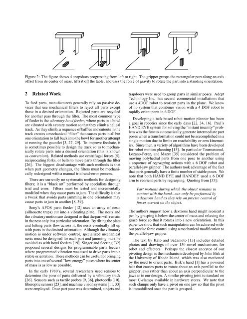
Figure 2: The figure shows 4 snapshots progressing from left to right. The gripper grasps the rectangular part along an axis<br />
offset from its center of mass, lifts it off the table, and uses the <strong>for</strong>ce of gravity to rotate the part into a standing orientation.<br />
2 Related Work<br />
To feed parts, manufacturers generally rely on passive devices<br />
that use mechanical filters to reject all parts except<br />
those in a desired orientation. Rejected parts are recycled<br />
<strong>for</strong> another pass through the filter. The most common type<br />
of feeder is the vibratory bowl feeder, where parts in a bowl<br />
are vibrated with a rotary motion so that they climb a helical<br />
track. As they climb, a sequence of baffles and cutouts in the<br />
track creates a mechanical “filter” that causes parts in all but<br />
one orientation to fall back into the bowl <strong>for</strong> another attempt<br />
at running the gauntlet [3, 27, 29]. To improve feedrate, it<br />
is sometimes possible to design the track so as to mechanically<br />
rotate parts into a desired orientation (this is known<br />
as conversion). Related methods use centrifugal <strong>for</strong>ces [5],<br />
reciprocating <strong>for</strong>ks, or belts to move parts through the filter<br />
[26]. The biggest disadvantage with such methods is that<br />
when part geometry changes, the filters must be mechanically<br />
redesigned with a manual trial-and-error process.<br />
There are currently no systematic methods <strong>for</strong> designing<br />
filters; it is a “black art” per<strong>for</strong>med by specialists through<br />
trial and error. Filters must be tested and incrementally<br />
modified when they cause parts to jam. The difficulty is that<br />
a tweak that avoids parts jamming in one orientation may<br />
cause parts to jam in another [8, 39].<br />
Sony’s APOS parts feeder [12] uses an array of nests<br />
(silhouette traps) cut into a vibrating plate. The nests and<br />
the vibratorymotion are designed so that thepart will remain<br />
in the nest only in a particular orientation. By tilting the plate<br />
and letting parts flow across it, the nests eventually fill up<br />
with parts in the desired orientation. Although the vibratory<br />
motion is under software control, specialized mechanical<br />
nests must be designed <strong>for</strong> each part and jamming must be<br />
avoided as with bowl feeders [19]. Singer and Seering [32]<br />
proposed several designs <strong>for</strong> programmable parts feeders<br />
where programmed vibration was used to drive parts into a<br />
stable orientation. These methods can be useful <strong>for</strong> bringing<br />
parts into one of several “low-energy” poses where its center<br />
of mass is as low as possible.<br />
In the early 1980’s, several researchers used sensors to<br />
determine the pose of parts delivered by a vibratory track<br />
[26]. Sensors such as tactile probes [9, 36], photocells [10],<br />
fiberoptic sensors [23], and machine vision systems [11, 33]<br />
were employed. Once part pose was determined, air-jets and<br />
trapdoors were used to group parts in similar poses. Adept<br />
Technology Inc. has several commercial installations that<br />
use a 4DOF robot to reorient parts in the plane. We know<br />
of no system that combines vision with a 4 DOF robot to<br />
rapidly orient parts in 6 DOF.<br />
Developing a task-based robot motion planner has been<br />
a goal in robotics since the early days [22, 34, 16]. Paul’s<br />
HAND EYE system <strong>for</strong> solving the “instant insanity” problem<br />
was the first to automatically generate intermediate part<br />
poses when a trans<strong>for</strong>mation could not be accomplished in a<br />
single motion due to limits on reachability or arm kinematics.<br />
Since then, a variety of algorithms have been developed<br />
<strong>for</strong> robot motion planning [15]. In particular Tournassoud,<br />
Lozano-Perez, and Mazer [35] considered the problem of<br />
moving polyhedral parts from one pose to another using<br />
a sequence of regrasping actions with a 6 DOF robot and<br />
parallel-jaw gripper. The authors took advantage of the fact<br />
that parts generally have a finite number of stable poses. We<br />
note that both HAND EYE and HANDEY used a 6 DOF<br />
arm to reorient parts by regrasping. Quoting from [35]:<br />
Part motions during which the object remains in<br />
contact with the hand...can only be per<strong>for</strong>med by<br />
a dextrous hand as they rely on precise control of<br />
<strong>for</strong>ces exerted on the object.<br />
The authors suggest how a dextrous hand might reorient a<br />
pen by grasping it below the center of mass and relaxing the<br />
grasp <strong>for</strong>ce so that it rotates into a new orientation. In this<br />
paper we show that such manipulation can be achieved without<br />
precise <strong>for</strong>ce control using a mechanical modification to<br />
the parallel-jaw gripper.<br />
The text by Kato and Sadamoto [13] includes detailed<br />
photos and drawings of over 150 novel mechanisms <strong>for</strong><br />
robot end effectors. Perhaps the closest ancestor of our<br />
pivoting design is the mechanism developed by John Birk at<br />
the University of Rhode Island, which was also motivated<br />
by the need to orient parts. Birk’s hand [1] has a powered<br />
belt that causes parts to rotate about an axis parallel to the<br />
gripper jaws rather than about an axis perpendicular to the<br />
jaws as in our design. A similar pivoting joint is standard on<br />
most C-clamps available in hardware stores. We note that<br />
such clamps only have a pivot on one jaw so that the pivot<br />
is immobilized once the part is grasped.