A Pivoting Gripper for Feeding Industrial Parts - Ken Goldberg
A Pivoting Gripper for Feeding Industrial Parts - Ken Goldberg
A Pivoting Gripper for Feeding Industrial Parts - Ken Goldberg

Create successful ePaper yourself
Turn your PDF publications into a flip-book with our unique Google optimized e-Paper software.
Brian Carlisle<br />
Adept Technology<br />
A <strong>Pivoting</strong> <strong>Gripper</strong> <strong>for</strong> <strong>Feeding</strong> <strong>Industrial</strong> <strong>Parts</strong><br />
<strong>Ken</strong> <strong>Goldberg</strong> y<br />
USC<br />
To be cost effective and highly precise, many industrial assembly<br />
robots have only four degrees of freedom (D.O.F. )<br />
plus a binary pneumatic gripper. Such robots commonly<br />
permit parts to be rotated only about a vertical axis. However<br />
it is often necessary to reorient parts about other axes<br />
prior to assembly. In this paper we describe a way to orient<br />
parts about an arbitrary axis by introducing a rotating<br />
bearing between the jaws of a simple gripper.<br />
Based on this mechanism, we are developing a rapidly<br />
configurable vision-based system <strong>for</strong> feeding parts. In this<br />
system, a camera determines initialpart pose; the robot then<br />
reorients the part to achieve a desired final pose. We have<br />
implemented a prototype version in our laboratory using a<br />
commercially-available robot system.<br />
1 Introduction<br />
To automate the assembly of mechanical components, parts<br />
must precisely oriented prior to packing or insertion. A<br />
parts feeder is a machine that orients parts. Currently, the<br />
design of parts feeders is a black art that is responsible<br />
<strong>for</strong> up to 30% of the cost and 50% of workcell failures<br />
[21, 3, 5, 30, 31]. “The real problem is not part transfer<br />
but part orientation.”, Frank Riley, Bodine Corporation [27,<br />
p.316, his italics]. Thus there is a demand <strong>for</strong> a parts feeder<br />
that can be reprogrammed rather than physically modified<br />
when part geometry changes.<br />
Our feeder design combines machine vision with a highspeed<br />
robot arm. The system is programmed based on the<br />
type of part to be fed. During operation, a collection of<br />
like parts are randomly scattered on a flat worktable where<br />
they are subject to the <strong>for</strong>ce of gravity. An overhead vision<br />
system determines the pose (position and orientation) of<br />
Adept Technology,Inc., 150 Rose Orchard Way, San Jose, CA<br />
95134. (408) 432-0888.<br />
y<br />
Institute <strong>for</strong> Robotics and Intelligent Systems, Computer Science<br />
Department, University of Southern Cali<strong>for</strong>nia, Los Angeles,<br />
CA 90089-0273, (213) 740-9080, goldberg@iris.usc.edu. <strong>Goldberg</strong><br />
and Wiegley are supported by the National Science Foundation<br />
under Award No. IRI-9123747, and by an equipment grant<br />
from Adept Technology Inc.<br />
z<br />
Department of Computer Science, Utrecht University, P.O.<br />
Box 80.089, Padualaan 14, 3508 TB Utrecht, The Netherlands.<br />
Rao is supported by the ESPRIT Basic Research Action No. 6546<br />
(project PRoMotion).<br />
xInstitute <strong>for</strong> Robotics and Intelligent Systems, Computer Science<br />
Department, University of Southern Cali<strong>for</strong>nia.<br />
Anil Rao z<br />
Univ. Utrecht<br />
Jeff Wiegley x<br />
USC<br />
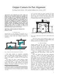
Figure 1: A parts feeder using a commercially-available<br />
system that integrates machine vision, high-speed robot arm,<br />
and pivoting gripper. This illustration shows the system<br />
feeding rectangular parts into a square pallet.<br />
each part. The robot arm then picks up each part and moves<br />
it into a desired final pose as illustrated in Figure 1.<br />
To be cost effective, fast, and highly precise, commercial<br />
assembly robots usually have only four degrees of freedom<br />
(4D.O.F. ). However parts must be reoriented and repositioned<br />
through six degrees of freedom (6D.O.F. ). To close<br />
this gap, we have designed a gripper with a rotational pivot<br />
between its jaws to provide an extra degree of freedom.<br />
Since cost and weight are critical, we note that the pivoting<br />
axis need not be actuated: it is possible to pick up each part<br />
along an axis offset from its center of mass and use on the<br />
<strong>for</strong>ce of gravity to rotate the part as illustrated in Figure 2.<br />
In this paper we describe related work on parts feeders and<br />
robot gripper mechanisms. In Sections 3 and 4 we describe<br />
the pivoting mechanism in detail and our experiments with<br />
a vision-based parts feeding system. Last, we discuss the<br />
advantages and disadvantages of the proposed system and<br />
describes avenues <strong>for</strong> future research.
Figure 2: The figure shows 4 snapshots progressing from left to right. The gripper grasps the rectangular part along an axis<br />
offset from its center of mass, lifts it off the table, and uses the <strong>for</strong>ce of gravity to rotate the part into a standing orientation.<br />
2 Related Work<br />
To feed parts, manufacturers generally rely on passive devices<br />
that use mechanical filters to reject all parts except<br />
those in a desired orientation. Rejected parts are recycled<br />
<strong>for</strong> another pass through the filter. The most common type<br />
of feeder is the vibratory bowl feeder, where parts in a bowl<br />
are vibrated with a rotary motion so that they climb a helical<br />
track. As they climb, a sequence of baffles and cutouts in the<br />
track creates a mechanical “filter” that causes parts in all but<br />
one orientation to fall back into the bowl <strong>for</strong> another attempt<br />
at running the gauntlet [3, 27, 29]. To improve feedrate, it<br />
is sometimes possible to design the track so as to mechanically<br />
rotate parts into a desired orientation (this is known<br />
as conversion). Related methods use centrifugal <strong>for</strong>ces [5],<br />
reciprocating <strong>for</strong>ks, or belts to move parts through the filter<br />
[26]. The biggest disadvantage with such methods is that<br />
when part geometry changes, the filters must be mechanically<br />
redesigned with a manual trial-and-error process.<br />
There are currently no systematic methods <strong>for</strong> designing<br />
filters; it is a “black art” per<strong>for</strong>med by specialists through<br />
trial and error. Filters must be tested and incrementally<br />
modified when they cause parts to jam. The difficulty is that<br />
a tweak that avoids parts jamming in one orientation may<br />
cause parts to jam in another [8, 39].<br />
Sony’s APOS parts feeder [12] uses an array of nests<br />
(silhouette traps) cut into a vibrating plate. The nests and<br />
the vibratorymotion are designed so that thepart will remain<br />
in the nest only in a particular orientation. By tilting the plate<br />
and letting parts flow across it, the nests eventually fill up<br />
with parts in the desired orientation. Although the vibratory<br />
motion is under software control, specialized mechanical<br />
nests must be designed <strong>for</strong> each part and jamming must be<br />
avoided as with bowl feeders [19]. Singer and Seering [32]<br />
proposed several designs <strong>for</strong> programmable parts feeders<br />
where programmed vibration was used to drive parts into a<br />
stable orientation. These methods can be useful <strong>for</strong> bringing<br />
parts into one of several “low-energy” poses where its center<br />
of mass is as low as possible.<br />
In the early 1980’s, several researchers used sensors to<br />
determine the pose of parts delivered by a vibratory track<br />
[26]. Sensors such as tactile probes [9, 36], photocells [10],<br />
fiberoptic sensors [23], and machine vision systems [11, 33]<br />
were employed. Once part pose was determined, air-jets and<br />
trapdoors were used to group parts in similar poses. Adept<br />
Technology Inc. has several commercial installations that<br />
use a 4DOF robot to reorient parts in the plane. We know<br />
of no system that combines vision with a 4 DOF robot to<br />
rapidly orient parts in 6 DOF.<br />
Developing a task-based robot motion planner has been<br />
a goal in robotics since the early days [22, 34, 16]. Paul’s<br />
HAND EYE system <strong>for</strong> solving the “instant insanity” problem<br />
was the first to automatically generate intermediate part<br />
poses when a trans<strong>for</strong>mation could not be accomplished in a<br />
single motion due to limits on reachability or arm kinematics.<br />
Since then, a variety of algorithms have been developed<br />
<strong>for</strong> robot motion planning [15]. In particular Tournassoud,<br />
Lozano-Perez, and Mazer [35] considered the problem of<br />
moving polyhedral parts from one pose to another using<br />
a sequence of regrasping actions with a 6 DOF robot and<br />
parallel-jaw gripper. The authors took advantage of the fact<br />
that parts generally have a finite number of stable poses. We<br />
note that both HAND EYE and HANDEY used a 6 DOF<br />
arm to reorient parts by regrasping. Quoting from [35]:<br />
Part motions during which the object remains in<br />
contact with the hand...can only be per<strong>for</strong>med by<br />
a dextrous hand as they rely on precise control of<br />
<strong>for</strong>ces exerted on the object.<br />
The authors suggest how a dextrous hand might reorient a<br />
pen by grasping it below the center of mass and relaxing the<br />
grasp <strong>for</strong>ce so that it rotates into a new orientation. In this<br />
paper we show that such manipulation can be achieved without<br />
precise <strong>for</strong>ce control using a mechanical modification to<br />
the parallel-jaw gripper.<br />
The text by Kato and Sadamoto [13] includes detailed<br />
photos and drawings of over 150 novel mechanisms <strong>for</strong><br />
robot end effectors. Perhaps the closest ancestor of our<br />
pivoting design is the mechanism developed by John Birk at<br />
the University of Rhode Island, which was also motivated<br />
by the need to orient parts. Birk’s hand [1] has a powered<br />
belt that causes parts to rotate about an axis parallel to the<br />
gripper jaws rather than about an axis perpendicular to the<br />
jaws as in our design. A similar pivoting joint is standard on<br />
most C-clamps available in hardware stores. We note that<br />
such clamps only have a pivot on one jaw so that the pivot<br />
is immobilized once the part is grasped.
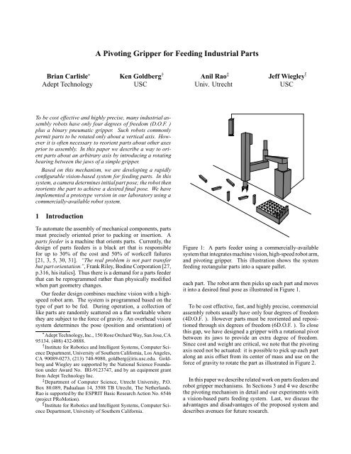
Figure 3: An exploded view of the mechanism <strong>for</strong> one pivoting pad. Frictional resistance to torsional and axial <strong>for</strong>ces are<br />
reduced with needle and thrust bearings as illustrated. The contacting pad can be of flat hard rubber (in our case a pencil<br />
eraser). The pad turns with the part, thereby insuring frictional resistance to slip as the part is lifted and transported.<br />
<strong>Goldberg</strong> and Furst developed a parallel-jaw gripper with<br />
a translational bearing rather than a rotational bearing. The<br />
translating bearing serves to reduce effective friction parallel<br />
to the support plane and thus aids in achieving a stable grasp.<br />
One similarity to the pivoting gripper is that the additional<br />
degree of freedom does not require an active servo system.<br />
Also, both grippers were designed <strong>for</strong> application to parts<br />
feeding [6].<br />
3 The <strong>Pivoting</strong> <strong>Gripper</strong> Mechanism<br />
Our idea <strong>for</strong> rotating parts requires two “hard finger” contacts,<br />
which are defined as contacts that can apply <strong>for</strong>ces<br />
pointingintothe friction cone but cannot resist torques about<br />
the contact point [28]. Clearly, a grasp with two hard finger<br />
contacts cannot achieve <strong>for</strong>m closure as the part is free to rotate<br />
about the contact axis. Indeed, [17] showed that 4 hard<br />
finger contacts are both necessary and sufficient to achieve<br />
<strong>for</strong>m closure on a polyhedron. However <strong>for</strong> feeding parts<br />
we do not require <strong>for</strong>m closure; we want to insure that the<br />
part will not translate when lifted, and in contrast to most<br />
work on grasping, we want to insure that the part will rotate<br />
about the grasp axis.<br />
One way to achieve hard finger contacts is to use sharpened<br />
points. Such point contacts are sensitive to small variations<br />
in part orientation and do not have the “self-aligning”<br />
benefits of flat contacts. Furthermore, point contacts may<br />
damage the part. To implement true hard finger contacts,<br />
the biggest problem is eliminating frictional resistance to<br />
torques about the pivot axis.<br />
We propose to use a bearing mechanism as illustrated in<br />
figure 3.<br />
An important consideration is that the bearing mechanism<br />
have a small footprint and also permit the pivoting axis<br />
to reach as close as possible to the worksurface to grasp<br />
small parts. Machining such a mechanism poses practical<br />
difficulties. We machined our own bearing races and used<br />
custom needle bearings to build a prototype with footprint<br />
13 22mm permitting the pivot axis to be lowered to within<br />
6mm of the worktable. We used flat-topped pencil erasers<br />
to provide high frictional resistance to translational <strong>for</strong>ces.<br />
We mounted a pair of these bearings on a commercial<br />
pneumatic parallel-jaw gripper. When the jaws are closed<br />
under air pressure, compressive <strong>for</strong>ces tax our thrust bearings<br />
and introduce frictional resistance to rotation. Fortunately,<br />
we have found that it is a simple matter to achieve<br />
compliant rotation by brushing parts against a fixed “lip” in<br />
the environment. The brushing movement can be achieved<br />
with a combination of vertical and horizontal movements of<br />
the arm, thus requiring no actuation at the pivot.<br />
4 The <strong>Parts</strong> <strong>Feeding</strong> System<br />
Our feeder design is based on a commercially-available system<br />
that integrates machine vision with a high-speed robot<br />
arm. The system is programmed based on the type of part<br />
to be fed. During operation, a collection of like parts are
dropped and randomly scattered on a flat worktable where<br />
they are subject to the <strong>for</strong>ce of gravity. A set of conveyor<br />
belts is used to singulate parts and transport them into the<br />
field of view of an overhead camera. Note that in general,<br />
parts will only have a finite number of stable poses under<br />
the influence of gravity. Each of these is treated as a unique<br />
pattern by the vision system, which identifies each pattern<br />
and its pose (position and orientation). Each pattern indexes<br />
into a pre-programmed manipulation routine <strong>for</strong> the pivoting<br />
gripper which picks up the part, reorients it if necessary,<br />
and moves it into a desired final pose. The process is then<br />
repeated <strong>for</strong> all parts that can be identified by the vision system.<br />
Remaining parts are recycled <strong>for</strong> another pass through<br />
the system.<br />
We implemented a prototype system in our laboratory<br />
using a commercially-available robot system: Adept 604-S<br />
SCARA type arm, standard CCD camera, and Adept’s AIM<br />
vision software. Figure 4 shows a photo of the system in<br />
our laboratory. In one case we placed registration marks on<br />
the parts to cope with ambiguous and symmetric poses (one<br />
method <strong>for</strong> locating such marks is described in [24]). We<br />
also used diffused overhead lighting to reduce shadows and<br />
specularities.<br />
In our initialexperiments, we hand-singulatedthe parts by<br />
dropping them one-by-one into the camera’s field of view.<br />
We also hand-coded the grasp points <strong>for</strong> each pattern. After<br />
the robot reorients the part and places it into a pallet, it<br />
returns to a home position and waits <strong>for</strong> the next part to<br />
be dropped into its field of view. We tested the system<br />
with two sets of parts: rectangular parts made of steel and<br />
orange insulating caps made of plastic. The latter parts were<br />
sufficiently lightweight that gravity didnot provide sufficient<br />
torque to overcome friction; in this case we brushed parts<br />
past a fixed lip to achieve the same effect.<br />
The resulting system worked quite reliably. We achieved<br />
feed rates of 5 seconds per part, including visual recognition<br />
of pose. In an industrial setting, the vision and manipulation<br />
can be pipelined to speed operation. The system was able to<br />
successfully feed parts about 90% of the time. Failures were<br />
typically due to errors in visual recognition, grasp location,<br />
or incomplete pivoting along the lip. A videotape of these<br />
experiments is available.<br />
5 Comparison with Existing Feeders<br />
Our goal is to develop a programmable system that efficiently<br />
feeds a broad class of industrial parts. <strong>Parts</strong> to be<br />
fed will be singulated with the aid of vibration and a series<br />
of conveyor belts traveling at different speeds; parts that are<br />
not recognized or are unable to be reoriented will be rejected<br />
and recirculated.<br />
This design <strong>for</strong> a programmable feeder offers the following<br />
advantages over previous methods:<br />
Fast set-up and changeover: The camera, robot arm,<br />
and gripper can be used <strong>for</strong> a wide variety of part<br />
shapes. To set-up <strong>for</strong> a new part, only the vision and<br />
manipulation routines must be changed.<br />
Figure 4: Experimental system in our laboratory.<br />
Less damage to sensitive parts: The proposed feeder<br />
is highly suited <strong>for</strong> delicate parts such as electronic or<br />
optical components.<br />
Compatibility with large and small parts. Vibratory<br />
bowls are generally limited to parts of diameter five<br />
inches or less due to restrictions on bowl diameter.<br />
Less Likely to jam: No mechanical filters are required.<br />
Lower Noise. OSHA Noise limits are 90 dBa, maximum<br />
employee exposure over eight hours. Shrouds to<br />
contain noise can add up to 25% to the cost of vibratory<br />
bowls [39].<br />
This feeder design is not intended as a universal panacea.<br />
The initial investment <strong>for</strong> the first feeder will be higher than<br />
that <strong>for</strong> conventional (hard-tooled) feeders. And certainly<br />
conventional feeders will be more cost effective <strong>for</strong> highvolume<br />
parts such as fasteners and washers. But our hunch<br />
is that the flexibility of the vision-based system will be cost<br />
effective in the long run <strong>for</strong> a variety of industrial applications.
6 Planning Algorithms<br />
To configure such a system <strong>for</strong> a new part, two changes in<br />
software are required: vision and manipulation routines. In<br />
our initial experiments the <strong>for</strong>mer was programmed using<br />
proprietary statistical decision software from Adept, and the<br />
latter was hand-coded. We are now workingto develop planning<br />
algorithms <strong>for</strong> automatically programming the system<br />
based on part geometry.<br />
GivenaCADmodelofapartanditscenterofmass,<br />
the first step is to determine all of the part’s stable poses<br />
under the <strong>for</strong>ce of gravity. For polyhedral parts, we can<br />
compute the convex hull of the part and check if the center<br />
of mass projects into each face. Clearly, a polygonal part<br />
with n faces can have no more than n stable poses. For more<br />
general classes of curved parts, we are working with Dave<br />
Kriegman to build on a recent algorithm described in [14].<br />
Each stable pose presents a projective image that can<br />
be identified by the vision system. Well-known methods<br />
exist <strong>for</strong> automatically generating shape recognition routines<br />
(some of these have been incorporated into Adept’s<br />
commercially-available software). We are also studying algorithms<br />
<strong>for</strong> automatically locating registration marks to<br />
reduce ambiguities.<br />
A primary challenge is to develop algorithms that, given<br />
a CAD model of a part, will automatically plan appropriate<br />
grasp strategies <strong>for</strong> each stable pose. Given polyhedral part<br />
shape and coefficient of friction as input, the problem is to<br />
find a (possibly empty) set of grasps that will achieve the<br />
following objectives [25]:<br />
The line connecting these contacts (the contact axis) is<br />
parallel to the worktable (due to the limited kinematics<br />
of the robot arm),<br />
The part will not slip as it is lifted off of the plane,<br />
The part will rotate about the contact axis as it is lifted<br />
due to the <strong>for</strong>ce of gravity and come to rest such that:<br />
When the part is replaced on the table it will assume<br />
the desired pose.<br />
Automatic planning software would permit offline analysis<br />
of the “feedability” of a proposed part, thereby providing<br />
designers with rapid feedback [38]. It may also be possible<br />
to to predict feedrates offline using a probabilistic analysis<br />
of pose stability, ie, system feedrate is related on the probability<br />
that a part will land on each of its stable faces [20, 7].<br />
We have implemented a method similar to that presented in<br />
[2], which starts with the convex hull of the part. Each face<br />
of this hull is projected onto a unit sphere centered on the<br />
part’s center of mass. This projected face defines a “capture<br />
range”, a set of contact orientations that will converge<br />
on enclosed face as the part falls under quasi-static conditions.<br />
An O(n 2 ) implementation is described in [37]. We<br />
acknowledge that more accurate prediction of pose probabilities<br />
would require us to model the complex dynamics of<br />
frictional collisions which is notoriously difficult [18].<br />
Many variations of the above system are possible. We<br />
might also include an active clutching mechanism <strong>for</strong> locking<br />
the pivot when part rotations are undesirable. This<br />
would, <strong>for</strong> example, allow the same gripper to be used <strong>for</strong><br />
feeding and inserting parts.<br />
The system described in this paper is an example of what<br />
might be called a “RISC” approach to industrial robotics:<br />
Reduced Intricacy in Sensing and Control [4]. The idea is<br />
to reduce complex manipulations to a sequence of primitive<br />
operations that can be per<strong>for</strong>med with simple mechanisms<br />
such as the pivoting gripper. A challenge is to develop<br />
robust planning algorithms that will automatically per<strong>for</strong>m<br />
this reduction. We believe that such algorithms can have<br />
near-term application to manufacturing.<br />
Acknowledgements<br />
We thank Tony Lewis, Mark Dane, and Dave Kriegman <strong>for</strong> their<br />
suggestions. We also thank John Elder <strong>for</strong> the photographs and<br />
Maria Wiegley <strong>for</strong> Figure 2.<br />
References<br />
[1] John Birk. A computer-controlled rotating-belt hand<br />
<strong>for</strong> object orientation. IEEE Trans. on Systems, Man,<br />
and Cybernetics, 4(2), March 1974.<br />
[2] G. Boothroyd,A. H. Red<strong>for</strong>d, C. Poli, and L. E. Murch.<br />
Statistical distributions of natural resting aspects of<br />
parts <strong>for</strong> automatic handling. SME Manufacturing Engineering<br />
Transactions, 1:72, 1972.<br />
[3] Geoffrey Boothroyd, Corrado Poli, and Laurence E.<br />
Murch. Automatic Assembly. Marcel Dekker, Inc.,<br />
1982.<br />
[4] John Canny and <strong>Ken</strong> <strong>Goldberg</strong>. “RISC” <strong>for</strong> industrial<br />
robotics: Recent results and open problems.<br />
In International Conference on Robotics<br />
and Automation. IEEE, May 1994. Also<br />
available as USC Techreport IRIS-93-315 and<br />
via anonymous ftp from 128.125.51.19 under<br />
pub/Tech Rept/Iris/1993/IRIS 93 315.ps.Z.<br />
[5] Gregory T. Farnum and Bill Davis. Delivering the part.<br />
Manufacturing Engineering, March 1986.<br />
[6] <strong>Ken</strong> <strong>Goldberg</strong>. Orienting polygonal parts without sensors.<br />
Algorithmica, 10(2):201–225,August 1993. Special<br />
Issue on Computational Robotics.<br />
[7] <strong>Ken</strong> <strong>Goldberg</strong> and Matthew T. Mason. Bayesian grasping.<br />
In International Conference on Robotics and Automation.<br />
IEEE, May 1990.<br />
[8] Jerry Goodrich and Gary Maul. Programmable parts<br />
feeders. <strong>Industrial</strong> Engineering Magazine, May 1983.<br />
Reprinted in Automated Assembly, Jack D. Lane ed.,<br />
published in 1986 by SME.<br />
[9] D. D. Grossman and M. W. Blasgen. Orienting mechanical<br />
parts by computer-controlled manipulator.
IEEE Trans. on Systems, Man, and Cybernetics, 5,<br />
1975.<br />
[10] J. Hartley. Picking parts from a bowlfeeder with image<br />
sensing. Sensor Review, 1(1), January 1981.<br />
[11] J. W. Hill. Programmable bowl feeder design based on<br />
computer vision. Assembly Automation, 1(1), November<br />
1980.<br />
[12] Hajime Hitakawa. Advanced parts orientation system<br />
has wide application. Assembly Automation, 8(3),<br />
1988.<br />
[13] Ichiro Kato and Kuni Sadamoto. Mechanical Hands<br />
Illustrated (Revised Edition). Hemisphere Publishing<br />
Corp, NYC, 1987 (originally published in 1982).<br />
[14] David J. Kriegman. Computing stable poses of piecewise<br />
smooth objects. CVGIP: Image Understanding,<br />
55(2), March 1992.<br />
[15] Jean-Claude Latombe. Robot Motion Planning.<br />
Kluwer Academic Press, 1991.<br />
[16] Tomas Lozano-Perez, Joe Jones, Emmanuel Mazer,<br />
and Pat O’Donnell. Handey: A Robot Task Planner.<br />
MIT Press, 1992.<br />
[17] Xanthippi Markenscoff, Luqun Ni, and Christos H.<br />
Papadimitriou. The geometry of grasping. IJRR, 9(1),<br />
February 1990.<br />
[18] Matthew T. Mason, <strong>Ken</strong> <strong>Goldberg</strong>, and Yu Wang.<br />
Progress in robotic manipulation. In 15th Grantees<br />
Conference on Production Research and Technology.<br />
National Science Foundation, January 1989.<br />
[19] Paul Moncevicz, Mark Jakiela, and Karl Ulrich. Orientation<br />
and insertion of randomly presented parts using<br />
viratory agitation. In ASME 3rd Conference on Flexible<br />
Assembly Systems, September 1991.<br />
[20] L. E. Murch and G. Boothroyd. Prediction efficiency<br />
of parts orienting system. Automation, 2, 1971.<br />
[21] James L. Nevins and Daniel E. Whitney. Computercontrolled<br />
assembly. Scientific American, 1978.<br />
[22] Richard Paul. Modelling, Trajectory Calculation, and<br />
Servoing of a computer Controlled Arm. PhD thesis,<br />
Stan<strong>for</strong>d AIM-177, November 1973.<br />
[23] D. Pherson. Programmable feeder <strong>for</strong> non-rotational<br />
parts. In 15th CIRP International Seminar on Manufacturing<br />
Systems, 1983.<br />
[24] Anil Rao and <strong>Ken</strong> <strong>Goldberg</strong>. Placing registration<br />
marks. IEEE Transactions on <strong>Industrial</strong> Electronics,<br />
Special Issue on <strong>Industrial</strong> Robotics, 1993. Accepted<br />
May 1993. A preliminary version appeared in the 1993<br />
IEEE International Conference on Robotics and Automation,<br />
Atlanta, GA, and as USC IRIS Technical<br />
Report 293, April 1992.<br />
[25] Anil Rao and <strong>Ken</strong> <strong>Goldberg</strong>. Planning grasps <strong>for</strong> a<br />
pivoting gripper. Technical report, USC Institute <strong>for</strong><br />
Robotics and Intelligent Machines, Oct 1993. USC<br />
Techreport IRIS-93-313.<br />
[26] A. H. Red<strong>for</strong>d and E. Lo. Robots in Assembly. Halsted<br />
Press, New York, 1986.<br />
[27] Frank J. Riley. Assembly Automation, A Management<br />
Handbook. <strong>Industrial</strong> Press, New York, 1983.<br />
[28] J. <strong>Ken</strong>neth Salisbury. Kinematic and Force Analysis<br />
of Articulated Hands. PhD thesis, Department of Mechanical<br />
Engineering, Stan<strong>for</strong>d University, May 1982.<br />
published in it Robot Hands and the Mechanics of<br />
Manipulation, MIT Press, 1985.<br />
[29] Ben-Zion Sandler. Robotics: Designing the Mechanisms<br />
<strong>for</strong> Automated Machinery. Prentice Hall, 1991.<br />
Chapter 7 summarizes results originally published (in<br />
Russian) in A. N. Rabinovitsh, Automatic Orientation<br />
and <strong>Parts</strong> <strong>Feeding</strong>, Technika, 1968.<br />
[30] Berhard J. Schroer. Electronic parts presentation using<br />
vibratory bowl feeders. Robotics, 3, 1987.<br />
[31] Neil C. Singer. Utilizing dynamic and static stability<br />
to orient parts. Master’s thesis, MIT, 1985.<br />
[32] Neil C. Singer and Warren Seering. Utilizing dynamic<br />
stability to orient parts. Journal of Applied Mechanics,<br />
54, 1987. See also Singer’s 1985 MIT Masters Thesis.<br />
[33] T. Suzuki. An approach to a flexible part-feeding system.<br />
In 1st International Conference on Assembly Automation,<br />
1980.<br />
[34] Russ H. Taylor. A Synthesis of Manipulator Control<br />
Programs from Task-Level Specification. PhD thesis,<br />
Stan<strong>for</strong>d AIM-282, july 1976.<br />
[35] Pierre Tournassoud, T. Lozano-Perez, and E. Mazer.<br />
Regrasping. In International Conference on Robotics<br />
and Automation. IEEE, May 1987.<br />
[36] S. S. M. Wang and Peter Will. Sensors <strong>for</strong> computer<br />
controlled mechanical assembly. <strong>Industrial</strong> Robot,<br />
March 1978.<br />
[37] Jeff Wiegley, Anil Rao, and <strong>Ken</strong> <strong>Goldberg</strong>. Computing<br />
a statistical distribution of stable poses <strong>for</strong> a polyhedron.<br />
In The 30th Annual Allerton Conference on<br />
Communication, Control, and Computing. University<br />
of Illinois at Urbana-Champaign, October 1992.<br />
[38] Randy Wilson and Jean-Claude Latombe. Reasoning<br />
about mechanical assembly. In The 30th Annual<br />
Allerton Conference on Communication, Control, and<br />
Computing. October 1992.<br />
[39] Richard D. Zimmerman. Updated art – parts feeding.<br />
In Assemblex VIII Conference. SME, March 1982.<br />
Reprinted in Automated Assembly, Jack D. Lane ed.,<br />
published in 1986 by SME.