(SEE) Testing - Radiation Effects & Analysis Home Page - NASA
(SEE) Testing - Radiation Effects & Analysis Home Page - NASA
(SEE) Testing - Radiation Effects & Analysis Home Page - NASA

You also want an ePaper? Increase the reach of your titles
YUMPU automatically turns print PDFs into web optimized ePapers that Google loves.
ionization potential, the LET is easily converted to a<br />
charge deposition rate. For example, in silicon, a charge<br />
deposition rate of 1 pC/μm corresponds to a LET of 98<br />
MeV/(mg/cm 2 ).<br />
Flux(#/cm 2 -s-MeV/n)<br />
1.E+04<br />
1.E+03<br />
1.E+02<br />
1.E+01<br />
1.E+00<br />
1.E-01<br />
1.E-02<br />
1.E-03<br />
1.E-04<br />
1.E-05<br />
1.E-06<br />
1.E-07<br />
1.E-08<br />
Fe<br />
GCR He<br />
100 mils Al shielding<br />
He<br />
C<br />
Mg<br />
H<br />
1.E-09<br />
1.E-01 1.E+00 1.E+01 1.E+02 1.E+03 1.E+04 1.E+05<br />
Energy (MeV/nucleon)<br />
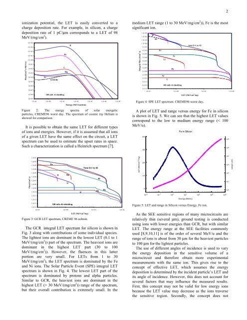
Figure 2: The energy spectra of solar energetic<br />
particles, CREME96 worst day. The spectrum of cosmic ray Helium is<br />
showed for comparison.<br />
It is possible to obtain the same LET for different types<br />
of ions and energies. However, if it is assumed that all ions<br />
of a given LET have the same effect on the circuit, a LET<br />
spectrum can be used to estimate the upset rates in space.<br />
Such a characterization is called a Heinrich spectrum [7].<br />
Flux(#/cm 2 -s)<br />
1.E-01<br />
1.E-02<br />
1.E-03<br />
1.E-04<br />
1.E-05<br />
1.E-06<br />
1.E-07<br />
1.E-08<br />
1.E-09<br />
1.E-10<br />
1.E-11<br />
1.E-12<br />
Fe<br />
1.E-13<br />
1.E-14<br />
100 mils Al shielding<br />
1.E-01 1.E+00 1.E+01 1.E+02<br />
LET (MeVcm 2 /mg)<br />
Figure 3: GCR LET spectrum, CREME 96 solmin.<br />
H<br />
He<br />
Li<br />
Total Z=1 to 92<br />
The GCR integral LET spectrum for silicon is shown in<br />
Fig. 3 along with contributions of some individual species.<br />
The lightest ions are dominant in the lowest LET (0.1 to 1<br />
MeV/(mg/cm 2 )) part of the spectrum. The heaviest ions are<br />
dominant in the highest LET part (30 to 100<br />
MeV/(mg/cm 2 )). However, the fluences in this latter<br />
portion are very small. For LETs from 1 to 30<br />
MeV/(mg/cm 2 ), the LET spectrum is dominated by the Fe<br />
and Ni ions. The Solar Particle Event (SPE) integral LET<br />
spectrum is shown in Fig. 4. The lowest LET part of the<br />
spectrum is dominated by protons and alpha particles.<br />
Similar to GCR, the heaviest ions are dominant in the<br />
highest LET (> 30 MeV/(mg/cm 2 )) range of the spectrum,<br />
but their overall contribution is extremely small. In the<br />
U<br />
Au<br />
Ni<br />
Pb<br />
medium LET range (1 to 30 MeV/mg/cm 2 )), Fe is the most<br />
significant ion.<br />
Integral Flux (#/cm 2 -s)<br />
1.E+03<br />
1.E+02<br />
1.E+01<br />
1.E+00<br />
1.E-01<br />
1.E-02<br />
1.E-03<br />
1.E-04<br />
1.E-05<br />
1.E-06<br />
1.E-07<br />
1.E-08<br />
1.E-09<br />
1.E-10<br />
1.E-11<br />
1.E-12<br />
H<br />
He<br />
Fe<br />
Au<br />
Li<br />
U<br />
Pb<br />
Ni<br />
100 mils Al shielding<br />
total Z=1 to 92<br />
1.E-13<br />
1.E-01 1.E+00 1.E+01 1.E+02<br />
LET (MeVcm 2 /mg)<br />
Figure 4: SPE LET spectrum. CREME96 worst day.<br />
A plot of LET and range versus energy for Fe in silicon<br />
is shown in Fig. 5. We can see that the highest LET values<br />
correspond to the low to medium energy range (< 100<br />
MeV/u).<br />
LET (MeVcm 2 /mg)<br />
40<br />
30<br />
20<br />
10<br />
0<br />
10 -2<br />
10 -1<br />
10 0<br />
Fe in Silicon<br />
10 1<br />
Energy (MeV/u)<br />
Figure 5: LET and range in Silicon versus Energy, Fe ion.<br />
As the <strong>SEE</strong> sensitive regions of many microcircuits are<br />
relatively thin (several μm), ground testing is conducted<br />
using ions with lower energies than GCR, but with similar<br />
LET. The energy range at the <strong>SEE</strong> facilities commonly<br />
used [8,9,10,11] is of the order of several MeV/u and the<br />
range of ions is about from 30 μm for the heaviest particles<br />
to 100 μm for the lightest particles.<br />
The use of different angles of incidence is used to vary<br />
the energy deposition in the sensitive volume of a<br />
microcircuit and therefore obtain more experimental<br />
measurements with the same ion. This gives rise to the<br />
concept of effective LET, which assumes the energy<br />
deposition is determined by the incident particle’s LET and<br />
its angle of incidence. However, this does not account for<br />
several factors that may influence the measured results.<br />
First, this concept may not be valid for low energy ions<br />
because the LET value may decrease as the ions traverse<br />
the sensitive region. Secondly, the concept does not<br />
10 2<br />
10 3<br />
10 4<br />
2<br />
10 6<br />
10 5<br />
10 4<br />
10 3<br />
10 2<br />
10 1<br />
10 0<br />
range (um)