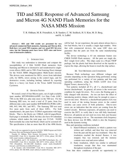
TID and SEE Response of Advanced Samsung and Micron 4G ...
TID and SEE Response of Advanced Samsung and Micron 4G ...
TID and SEE Response of Advanced Samsung and Micron 4G ...

Create successful ePaper yourself
Turn your PDF publications into a flip-book with our unique Google optimized e-Paper software.
NSREC09_Oldham_W9 1<br />
<strong>TID</strong> <strong>and</strong> <strong>SEE</strong> <strong>Response</strong> <strong>of</strong> <strong>Advanced</strong> <strong>Samsung</strong><br />
<strong>and</strong> <strong>Micron</strong> <strong>4G</strong> NAND Flash Memories for the<br />
NASA MMS Mission<br />
T. R. Oldham, M. R. Friendlich, A. B. S<strong>and</strong>ers, C. M. Seidleck, H. S. Kim, M. D. Berg,<br />
<strong>and</strong> K. A. LaBel<br />
Abstract— <strong>SEE</strong> <strong>and</strong> <strong>TID</strong> results are presented for two<br />
advanced commercial flash memories, <strong>Samsung</strong> <strong>and</strong> <strong>Micron</strong> <strong>4G</strong>b.<br />
Both have very good <strong>TID</strong> response, <strong>and</strong> very good SEU bit error<br />
rates, but the <strong>Samsung</strong> parts have lower SEFI rates <strong>and</strong> lower<br />
rates <strong>of</strong> destructive failures.<br />
I. INTRODUCTION<br />
This study was undertaken to determine <strong>and</strong> compare the<br />
susceptibilities <strong>of</strong> 4 Gbit NAND Flash memories from<br />
<strong>Samsung</strong> <strong>and</strong> <strong>Micron</strong> to destructive <strong>and</strong> nondestructive singleevent<br />
effects (<strong>SEE</strong>) <strong>and</strong> to <strong>TID</strong> (Total Ionizing Dose) damage<br />
for the NASA MMS (Magnetosphere Multi-Scale) mission.<br />
The devices were monitored for SEUs, errors from individual<br />
cells, for SEFIs, errors arising in the control logic, <strong>and</strong> for<br />
destructive events, including latchup, induced by exposing<br />
them to a heavy ion beam at the Texas A&M University<br />
Cyclotron.<br />
II. DEVICES TESTED<br />
We tested a total <strong>of</strong> four <strong>Micron</strong> parts, out <strong>of</strong> eight available<br />
(part number MT29F<strong>4G</strong>08AAAWP, Lot Date Code (LDC)<br />
748) in the <strong>SEE</strong> test, plus nine more in the <strong>TID</strong> test. For the<br />
<strong>Samsung</strong> <strong>SEE</strong> tests, we used a total <strong>of</strong> 23 parts, from five<br />
different date codes (part number K9F<strong>4G</strong>08U0A-PCB0, LDCs<br />
840, 843, 846, 901, <strong>and</strong> 907). The <strong>Samsung</strong> <strong>TID</strong> test used<br />
five more parts from each <strong>of</strong> these LDCs. For both<br />
manufacturers, the parts have 512Mx8 organization with large<br />
blocks. That is, the blocks are 128Kx8, with 64 pages/block.<br />
Each page is nominally 2Kx8, but they also have 64 redundant<br />
columns, which makes the total page size 2112x8. NAND<br />
flash normally has some bad blocks which can be screened <strong>of</strong>f.<br />
The specification is that no more than 80 <strong>of</strong> the 4096 blocks<br />
This work was supported in part by the NASA’ MMS Program <strong>and</strong> NASA<br />
Electronic Parts <strong>and</strong> Packaging Program (NEPP).<br />
Timothy R. Oldham, Perot Systems Government Services, Inc., c/o<br />
NASA/GSFC, Code 561.4, Greenbelt, MD 20771 (USA), phone: 301-286-<br />
5489, email: timothy.r.oldham@nasa.gov.<br />
M. Friendlich, <strong>and</strong> C. M. Seidleck are with MEI Technologies, Inc., c/o<br />
NASA/GSFC, Code 561.4, Greenbelt, MD 20771 (USA), phone: 301-286-<br />
7563 (Friendlich), 301-286-1009 (Seidleck), email: mark.r.friendlich@<br />
nasa.gov, <strong>and</strong> Christina.m.seidleck@nasa.gov.<br />
A. B. S<strong>and</strong>ers with NASA/GSFC, Code 561.4, Greenbelt, MD 20771<br />
(USA), phone: 301-286-8046, email: anthony.b.s<strong>and</strong>ers@nasa.gov.<br />
will be bad. In our experience, the parts almost always have a<br />
few bad blocks, but it is usually a single digit number. Note<br />
that with commercial devices, the same LDC does not<br />
guarantee that the parts are from the same manufacturing<br />
facility.<br />
The device technology is 63 nm minimum feature size<br />
CMOS NAND Flash memory. All the parts are single die,<br />
SLC (single level cells). The chips came in a 48-pin TSOP<br />
package, but the plastic had been dissolved on the topside to<br />
expose the chips, allowing the beam to reach the chip surface.<br />
III. TEST METHODS AND CONDITIONS<br />
Because Flash technology uses different voltages <strong>and</strong><br />
circuitry depending on the operation being performed, testing<br />
was performed for a variety <strong>of</strong> test patterns <strong>and</strong> bias <strong>and</strong><br />
operating conditions, using the NASA LCDT (low Cost<br />
Digital Tester), shown in Fig. 1.<br />
Test patterns included all 0’s, all 1’s, checkerboard <strong>and</strong><br />
inverse checkerboard. In general, all zeroes is the worst-case<br />
condition for single bit errors. For a zero, the floating gate is<br />
fully charged with electrons. An ion can have the effect <strong>of</strong><br />
introducing positive charge, which may be enough to cause a<br />
zero-to-one error. However, a checkerboard pattern (AA) was<br />
used in most <strong>of</strong> the testing because errors in the control<br />
circuitry can cause errors <strong>of</strong> both polarities. One-to-zero<br />
errors are an indication that the errors are coming from the<br />
control circuits. Between exposures, all patterns can used to<br />
exercise the DUT, to verify that it was still fully functional.<br />
However, all patterns are not used on every shot, just because<br />
it is time consuming to do so. The maximum clock frequency<br />
for these devices was 40 MHz, which is also the frequency<br />
used in the dynamic testing.<br />
Bias <strong>and</strong> operating conditions included:<br />
1) Static/Unbiased irradiation, in which a pattern was<br />
written <strong>and</strong> verified, <strong>and</strong> then bias was removed<br />
from the part <strong>and</strong> the part was irradiated. Once the<br />
irradiation reached the desired fluence, it was<br />
stopped, bias was restored, <strong>and</strong> the memory<br />
contents were read <strong>and</strong> errors tallied.<br />
2) Static irradiation, which was similar to unbiased<br />
irradiation, except that bias was maintained<br />
throughout irradiation <strong>of</strong> the part.<br />
Note that these conditions provide no opportunity to
NSREC09_Oldham_W9 2<br />
monitor functional or hard failures that may occur during the<br />
irradiation.<br />
3) Dynamic Read, in which a pattern was written to<br />
memory <strong>and</strong> verified, then subsequently read<br />
continuously during irradiation. This condition<br />
allows determination <strong>of</strong> functional, configuration<br />
<strong>and</strong> hard errors, as well as bit errors. In this mode,<br />
the number <strong>of</strong> static bit errors is determined by<br />
reading the memory again, after the beam is turned<br />
<strong>of</strong>f.<br />
4) Dynamic Read/Write, which was similar to the<br />
Dynamic Read, except that a write operation is<br />
performed on each word found to be in error<br />
during the previous Read.<br />
5) Dynamic Read/Erase/Write, which again was<br />
similar to the Dynamic Read <strong>and</strong> Read/Write,<br />
except that a word in error was first erased <strong>and</strong><br />
then rewritten. In this mode, the words that are<br />
read are compared to an “expected” pattern, which<br />
is actually the complement <strong>of</strong> the stored pattern.<br />
For this reason, every word is erased, as if it were<br />
in error. Because the Erase <strong>and</strong> Write operations<br />
use the charge pump, it is expected that the Flash<br />
could be more vulnerable to destructive conditions<br />
during these operations.<br />
6) Latchup (SEL) testing was conducted at 70º C, <strong>and</strong><br />
3.6 V. There were no cases where SEL was<br />
observed, but there were other destructive failures<br />
at high temperature. Therefore, we did extensive<br />
testing in the range 40-70º�C at 3.3 V, although we<br />
did not consider it to be SEL testing. The goal <strong>of</strong><br />
this high temperature testing was to detect<br />
destructive events, other than SEL.<br />
7) In this set <strong>of</strong> experiments, we have attempted to<br />
look at angular effects, which may include multiple<br />
bits grazed by the same ion, <strong>and</strong> other effects due<br />
to charge sharing by multiple nodes in the control<br />
logic. This test was done with at 45 degrees, which<br />
was close to the maximum possible angle, because<br />
the socket would have blocked the beam at angles<br />
much higher. There were two orientations, which<br />
we referred to as 45º North, <strong>and</strong> 45º East.<br />
Although the normal bit error upset rate is<br />
somewhat higher at high angles, probably because<br />
<strong>of</strong> charge sharing in the control logic, destructive<br />
failures occur primarily at normal incidence. For<br />
this reason, much <strong>of</strong> the high temperature testing<br />
was done at normal incidence.<br />
<strong>TID</strong> testing was done at a Co-60 facility, which is a room air<br />
source, where the Co-60 rods are raised up out <strong>of</strong> the floor,<br />
during exposures. Active dosimetry is performed, using air<br />
ionization probes. Testing is done in a step/stress manner,<br />
using a st<strong>and</strong>ard Pb/Al filter box. Dose rate typically varies<br />
slightly from one exposure to the next, up to 12 rads/s. The<br />
source no longer delivers the dose rate called for by MIL-STD<br />
Test Method 1019.7, but it is still well above the dose rate<br />
encountered in a space environment. Time intervals for testing<br />
between exposures are within the limits stated in 1019.7 (one<br />
hour after exposure to start electrical characterization, two<br />
hours to begin the next exposure). Parts were under DC bias<br />
during exposures, but not actively exercised.<br />
Fig. 1. LCDT Test System<br />
Fig. 2. Unbiased static results: (a) <strong>Micron</strong>; (b) <strong>Samsung</strong>
NSREC09_Oldham_W9 3<br />
<strong>SEE</strong> testing was done at the Texas A&M Cyclotron, using<br />
the 15 MeV/ nucleon tune, using the ions given in Table I:<br />
TAMU<br />
Ions<br />
TABLE I: IONS/ENERGIES AND LET FOR THIS TEST.<br />
Energy/<br />
AMU<br />
Energy<br />
(MeV)<br />
Approx. LET<br />
on die<br />
(MeV•cm 2 /mg)<br />
Angle Effective<br />
LET<br />
Ne 15 300 2.8 0, 45 2.8, 3.9<br />
Ar 15 600 8.4 0,45 8.4, 11.8<br />
Kr 15 1260 30.1 0, 45 30.1, 41<br />
Xe 15 1965 54.8 0, 45 54.8, 75<br />
Au 15 2955 87.5 0 87.5<br />
IV. RESULTS<br />
During testing, the DUTs were irradiated with the ions<br />
indicated in Table I. The DUT was oriented normal to the<br />
incident beam, or at 45 degrees. The errors observed in static<br />
SEU testing are shown in Fig. 2, with no bias applied. The 45<br />
degree data is plotted at the effective LET (LET/cos θ). This<br />
is done so that one can distinguish between the normal<br />
incidence shots <strong>and</strong> the 45 degree shots. It is not done because<br />
effective LET is expected to be a useful concept for other<br />
reasons.<br />
In the unbiased static mode, for the <strong>Micron</strong> parts , there<br />
were two exposures at 45º incidence with Ar ions (LET=8.4),<br />
which produced two SEFIs <strong>and</strong> one destructive failure <strong>of</strong> the<br />
erase circuit. We did not have enough samples to destroy<br />
them at that rate, especially at such low LET, so we<br />
concentrated on getting normal incidence results. We intended<br />
to return to high angle exposures later, but ran out <strong>of</strong> beam<br />
time before we could do so. For the <strong>Samsung</strong> parts, many<br />
more exposures were required, because five different LDCs<br />
had to be tested separately. In all, there were 27 shots in this<br />
test mode for the <strong>Samsung</strong> parts. Fourteen <strong>of</strong> these were at<br />
high angle. There was only one destructive failure, with Au<br />
ions at normal incidence—that is, at LET about an order <strong>of</strong><br />
magnitude higher than for the <strong>Micron</strong> destructive failure. The<br />
results for both manufacturers are summarized in Fig. 2.<br />
In the static mode with bias, for the <strong>Micron</strong> parts, there<br />
were 36 SEFIs due to block errors (where an entire block <strong>of</strong><br />
128Kx8 bits was lost, presumably due to a single ion), plus<br />
four other SEFIs, one <strong>of</strong> which was a destructive latchup<br />
(SEL). For the <strong>Samsung</strong> parts, there were a total <strong>of</strong> 27 shots,<br />
with 18 shots at oblique angles, with three SEFIs <strong>and</strong> no<br />
destructive failures. These results are summarized in Fig. 3.<br />
Fig. 3a. SEU, SEFI, <strong>and</strong> destructive failure results for <strong>Micron</strong> parts, in static<br />
mode with bias.<br />
Fig 3b. <strong>Samsung</strong> results for SEU, SEFI, <strong>and</strong> destructive failures, in static<br />
mode with bias.<br />
For the Dynamic Read mode, results are shown in Fig. 4, for<br />
both manufacturers. Here, <strong>and</strong> also in the other dynamic test<br />
modes, transient errors are defined as those observed while the<br />
part is operating with the beam on. Static errors are the bits in<br />
error after the beam is turned <strong>of</strong>f. For the <strong>Micron</strong> parts, there<br />
were a total <strong>of</strong> ten shots, with 36 block errors <strong>and</strong> two other<br />
SEFIs, with no destructive events. For the <strong>Samsung</strong> parts,<br />
there were 24 shots, including 17 at high angles, with two<br />
SEFIs <strong>and</strong> no destructive events.
NSREC09_Oldham_W9 4<br />
Fig. 4a. <strong>Micron</strong> dynamic read mode results for SEU, SEFI, <strong>and</strong> destructive<br />
failures.<br />
Fig 4b. <strong>Samsung</strong> dynamic read mode results for SEU, SEFI, <strong>and</strong> destructive<br />
failures.<br />
Results for the Dynamic R/W mode, for both manufacturers,<br />
are shown in Fig 5. For the <strong>Micron</strong> parts, there were ten shots<br />
in this test mode, there were 48 block errors <strong>and</strong> one other<br />
SEFI, <strong>and</strong> no destructive events. For the <strong>Samsung</strong> parts, there<br />
were 32 shots, including 24 at high angle, <strong>and</strong> nine at high<br />
temperature, with eight SEFIs <strong>and</strong> two destructive events.<br />
These were an erase failure with Au ions <strong>and</strong> a write failure<br />
with Xe ions.<br />
Fig 5a. <strong>Micron</strong> dynamic R/W mode results for SEU, SEFI, <strong>and</strong> destructive<br />
failures.<br />
Fig 5b. <strong>Samsung</strong> dynamic R/W mode results for SEU, SEFI, <strong>and</strong> destructive<br />
failures.<br />
Results for the Dynamic R/E/W test mode are shown in Fig.<br />
6 for both manufacturers. In this mode, the high voltage erase<br />
<strong>and</strong> write operations are both being performed, so it was<br />
expected that this would be the worst case test condition for<br />
failures related to those operations. For the <strong>Micron</strong> parts,<br />
there were 15 shots, with 33 block errors <strong>and</strong> one other SEFI,<br />
plus one destructive latchup (SEL). For the <strong>Samsung</strong> parts,<br />
there were 77 shots in this mode, including 46 at high angle,<br />
<strong>and</strong> 54 at elevated temperature. In the first test trip, we found<br />
that the <strong>Samsung</strong> parts failed at high temperature (70º C) more<br />
<strong>of</strong>ten than at room temperature. Therefore, we made a second<br />
test trip to examine this temperature sensitivity in more detail.<br />
The <strong>Micron</strong> parts, on the other h<strong>and</strong>, failed at all temperatures,<br />
so we did not pay special attention to their high temperature<br />
response. The <strong>Samsung</strong> parts had 24 SEFIs <strong>and</strong> nine<br />
destructive events. These destructive events occurred only at<br />
normal incidence, even though most shots were at high angle.<br />
They occurred mostly (six <strong>of</strong> the nine events) at high<br />
temperature, <strong>and</strong> with high LET ions (eight <strong>of</strong> the nine with Xe<br />
or Au ions). The high temperature results for the <strong>Samsung</strong><br />
parts for all the test modes are summarized in Table II.
NSREC09_Oldham_W9 5<br />
Fig 6a. <strong>Micron</strong> results in dynamic R/E/W mode for SEU, SEFI, <strong>and</strong><br />
destructive failures.<br />
Summarizing the results <strong>of</strong> these tests: all the high T failures<br />
were with Xe ions (LET=56), none were observed with Kr<br />
(next lowest LET=31). Because there were no failures with Kr,<br />
no testing was done with other, lower LET ions. All the high<br />
temperature failures were at normal incidence—there was not<br />
a single failure at high angles. All the failures occurred in<br />
either the R/E/W test mode or the R/W mode—there were no<br />
failures if the high voltage erase <strong>and</strong> write operations were not<br />
being performed. Summarizing the results in Table II by<br />
LDC:<br />
1) LDC 840 had four parts that failed in either the<br />
R/E/W or R/W test modes. Two failed on the first<br />
70º C shot at normal incidence, in the first test run.<br />
Two more failed at room temperature <strong>and</strong> normal<br />
incidence in second test.<br />
2) LDC 843, there were two erase failures at room<br />
temperature <strong>and</strong> normal incidence in the first test.<br />
One was with Au ions in the Dynamic Read mode,<br />
<strong>and</strong> the other was in R/E/W mode with Ar ions. In<br />
the second test, there was one additional failure,<br />
with Xe ions at high temperature. This sample<br />
failed on the first high temperature shot at normal<br />
incidence, at 40º C, but it had survived 11 other<br />
shots at higher angles, at temperatures over the<br />
range 40-70º C. This part had a write mode<br />
failure, but it was unlike the other write mode<br />
failures. In most cases, when the write circuit<br />
failed, it failed completely, <strong>and</strong> every address in<br />
the entire memory was bad. For this part, however,<br />
the write circuit worked for all but 159 addresses<br />
(stuck bits), even though it was drawing 53 mA,<br />
compared to 15-16 mA, nominal write current.<br />
This was an incomplete write, not a complete<br />
failure.<br />
3) LDC 846 had one write failure at normal incidence<br />
<strong>and</strong> room temperature with Au ions in the first test.<br />
One other sample failed in the second test at<br />
Fig 6b. <strong>Samsung</strong> results in dynamic R/E/W mode for SEU,SEFI, <strong>and</strong><br />
destructive failure.<br />
normal incidence <strong>and</strong> 40º C, with Xe ions. This<br />
part had survived three previous shots at 45º<br />
incidence, <strong>and</strong> 40-70º C.<br />
4) LDC 901 had a write failure with Au ions at normal<br />
incidence <strong>and</strong> room temperature, <strong>and</strong> another write<br />
failure with Xe ions (normal incidence, 70º C) in<br />
the first test. In the second test, there was one<br />
additional failure, at normal incidence <strong>and</strong> 70º C.<br />
However, the sample had survived four previous<br />
shots at 45º incidence, 40-70º C, <strong>and</strong> also four<br />
shots at normal incidence, over the same<br />
temperature range. This sample had survived one<br />
shot at 70º C <strong>and</strong> normal incidence, with fluence <strong>of</strong><br />
10 4 particles/cm 2 , but it failed on a second shot<br />
under these conditions, when the fluence was<br />
increased to 10 5 particles/cm 2 .<br />
5) LDC 907 had only one sample tested, because <strong>of</strong><br />
what we believe was corrosion on the leads <strong>of</strong><br />
several others, which made them unusable. This<br />
one sample was exposed for no less than 31 shots,<br />
all with Xe, <strong>and</strong> 15 <strong>of</strong> them at elevated<br />
temperature. It survived twelve shots at 45º<br />
incidence, 40-70º C. It also survived two normal<br />
incidence shots at 40º C, before failing at 50º C.<br />
The write current had risen on this part, from the<br />
normal 15-16 mA, to above 25 mA, before the<br />
normal incidence shots began. For this reason, we<br />
expected it to fail, before it actually did, as a result<br />
<strong>of</strong> cumulative damage. Damage on the shot where<br />
failure actually occurred was only a small part <strong>of</strong><br />
the story, for this part.
NSREC09_Oldham_W9 6<br />
TABLE II. SUMMARY OF SAMPLES USED AND FAILURE MODES.<br />
LDC Sample No. No. Shots Ion Fluence<br />
(p/cm 2<br />
Angle T (º C) Comments<br />
) (degrees)<br />
840-Test trip 1 2 1 Au 9e6 0 25 Unbiased static, erase failure<br />
3 10 Ne 1e7 0 25 1 SEFI, still functional<br />
3 1 Xe 1e5 0 70 R/E/W—write fail<br />
4 1 Xe 1e4 0 70 R/E/W—write fail<br />
840-Test trip 2 B7 10 Xe 1e4/shot 5 @0, 5@45 25 Write fail in R/W mode, normal<br />
inc.<br />
B6 1 Xr 1e4 0 25 Write fail, R/E/W<br />
843-Test trip 1 1 3 Au 1.2E5 total 0 25 Erase fail—Dyn. Read<br />
2 10 Ne 1e7/shot 5@0, 5@45 25 1 SEFI, but still functional<br />
7 10 Xe 1e4/shot 5@0, 5@45 25 1 SEFI, but still functional<br />
3 10 Kr 1e5/shot 5@0, 5@45 25 1 SEFI, but still functional<br />
4 5 Ar 1e6/shot 5@45 25 Erase fail—R/E/W<br />
843-Test trip 2 20 12 Xe 1e4/shot 11@45E, 40-70 Normal inc. fail from stuck bits<br />
1 normal 40 (incomplete write)—R/E/W<br />
22 6 Kr 1e5/shot 2@45E, 4@0 40-70<br />
40-70<br />
1 SEFI, but still functional<br />
846-Test trip 1 4 2 Au 1e4/shot 0 25 R/W—write fail<br />
7 5 Ne 1e7/shot 45 25 No SEFIs, fully functional<br />
5 Xe 1e4/shot 45 25 No SEFIs, fully functional<br />
6 Kr 1e5/shot 45 25 3SEFIs, fully functional<br />
5 Ar 1e6/shot 45 25 No SEFIs, fully functional<br />
846-Test trip 2 B10 4 Xe 1e4/shot 3 @ 45, 40-70 Write fail at normal inc.,<br />
1@ 0 40 R/E/W<br />
B12 12 Kr 1e5/shot 4 @ 45,<br />
4 @ 0<br />
40-70<br />
40-70<br />
4 total SEFIs, but fully functional<br />
901-Test trip 1 1 2 Au 3.5e4 total 0 25 Write fail—R/E/W<br />
3 5 Ne 1e7/shot 45 25 No SEFIs, fully functional<br />
5 Xe 1e4/shot 45 25 No SEFIs, fully functional<br />
1 Xe 1e5 45 70 SEFI, functional after PC<br />
4 1 Xe 1e5 0 70 Write fail<br />
6 5 Kr 1e5/shot 45 25 No SEFIs, fully functional<br />
5 Ar 1e6/shot 45 25 No SEFIs, fully functional<br />
901-Test trip 2 B04 9 Xe 1e4/shot 4 @ 45, 40-70 Write fail at normal inc., 70 C<br />
5@ 0 40-70 R/E/W<br />
B03 7 Kr 1e5/shot 3 @ 45,<br />
4 @ 0<br />
40-70<br />
40-70<br />
2 SEFIs, fully functional<br />
907-Test trip 2 13 6 Xe 1e4/shot 0 25 No SEFI, fully functional<br />
10 Xe 1e4/shot 45 25 No SEFIs, fully functional<br />
6 Xe 2.4e5 total 45 70 1 SEFI, fully functional<br />
6<br />
Xe 1e4/shot 45 2 ea. @ 40, 1 SEFI, fully functional<br />
50, 60<br />
3 Xe 1e4/shot 0 2 @ 40,<br />
1 @50<br />
The power supply current was monitored on all shots, <strong>and</strong><br />
representative sample traces are shown in Figs. 7-11. Typical<br />
power supply current traces are shown in Figs. 7 <strong>and</strong> 8 for two<br />
exposures using Xe ions in the R/E/W test mode. Fig 7 is at<br />
25º C, <strong>and</strong> neither a permanent failure, nor a SEFI occurred.<br />
Fig. 8 is at 70º C, <strong>and</strong> both a SEFI <strong>and</strong> a permanent write<br />
Write fail @ 50, R/E/W<br />
Write current high before normal<br />
inc. shots<br />
failure occurred. For these parts, normal read current is about<br />
10-11 mA,, <strong>and</strong> write current in a fresh part is about 15-17<br />
mA, although it increases as a part degrades over multiple<br />
shots. Erase current is 8-9 mA, <strong>and</strong> the current is about 4 mA,<br />
when the part is idling, not doing anything. In Fig. 7, the<br />
sample starts to read, <strong>and</strong> then the beam is turned on, <strong>and</strong> write
NSREC09_Oldham_W9 7<br />
pulses start, as errors are found. Write pulses continue after<br />
the beam is <strong>of</strong>f, until all the errors are corrected, but the part<br />
continues to read after that, just to make sure. Finally, there is<br />
another read to verify the part is ready for the next shot. Fig. 8<br />
shows the sample starting to read, then to have write pulses as<br />
errors begin to occur, but then the current increases to 20, 30,<br />
40, 50 mA, <strong>and</strong> higher. When the beam is <strong>of</strong>f, current<br />
stabilizes at about 57 mA. The write circuit had failed—the<br />
bit map showed the entire memory erased, because the erase<br />
circuit still worked, but none <strong>of</strong> the rewrite operations were<br />
successful. Fig. 9 shows the power supply current for a static<br />
(with bias) shot, where no SEFI occurred. The sample idles at<br />
4 mA while the beam is on. After the beam is <strong>of</strong>f, there is a<br />
read operation to count errors, <strong>and</strong> a second read to check for<br />
annealing, then an erase to prepare for the next shot, a read to<br />
verify the erase, a write to restore the test pattern <strong>and</strong> a final<br />
read to verify the write. Fig. 10 shows a similar power supply<br />
trace, for a Dynamic read mode shot. The sample reads while<br />
the beam is on, then there is another read to count static errors<br />
after the beam is <strong>of</strong>f, followed by an erase, a read to verify the<br />
erase, a write, <strong>and</strong> another read to verify the part is ready for<br />
the next shot. Fig . 11 shows results for a R/W mode shot.<br />
The sample writes while the beam is on, then reads static<br />
errors (twice), then erases, reads, writes, <strong>and</strong> reads again to<br />
verify the part is ready for the next shot. Note that in none <strong>of</strong><br />
these current traces do we see the current spikes that have been<br />
reported elsewhere [1].<br />
Fig. 7. Power supply current in R/E/W mode, Xe ions, at 25° C, with no<br />
permanent failure.<br />
Fig. 8. Power supply current in R/E/W mode, Xe ions, at 70° C, with<br />
permanent write mode failure.<br />
Fig.9. Power supply current in Static mode, with bias, Ar ions, with no<br />
failure.<br />
Fig. 10. Power supply current in Dynamic Read mode, Kr ions, with no<br />
failure.
NSREC09_Oldham_W9 8<br />
Fig. 11. Power supply current in R/W mode, Xe ions, with no failure.<br />
Both the <strong>Micron</strong> <strong>and</strong> <strong>Samsung</strong> parts had very good <strong>TID</strong><br />
response. The first failure, <strong>of</strong> nine <strong>Micron</strong> parts tested,<br />
occurred between 160 <strong>and</strong> 170 krads (SiO2). The other eight<br />
parts were still functional at 200 krads (SiO2), when the test<br />
was stopped, because the equipment had to be shipped for the<br />
<strong>SEE</strong> tests. For the <strong>Samsung</strong> parts, there was some variation<br />
between LDCs, but no part failed at less than 150 krads (SiO2).<br />
For the most recent LDC, 907, the parts all passed at 200 krads<br />
(SiO2), <strong>and</strong> failed at 225 krads (SiO2).<br />
V. DISCUSSION<br />
In the first test run for the <strong>Samsung</strong> parts, we had three<br />
destructive write mode failures at normal incidence, <strong>and</strong> 70º C,<br />
with Xe ions. We estimated it took about 52,000<br />
particles/cm 2 , to produce these failures. In the second, followup<br />
test, only one sample (LDC 901, sample B04) was tested at<br />
70º C <strong>and</strong> normal incidence. All the others failed at lower<br />
temperature, before we could get to 70º C. This one sample<br />
survived one shot with fluence 10 4 particles/cm 2 , <strong>and</strong> failed<br />
part way through another exposure to 10 5 particles/cm 2 . If we<br />
estimate the total fluence to failure at 3x10 4 particles/cm 2 , then<br />
we have four total failures with a mean fluence between<br />
failures a little over 2x10 4 particles/cm 2 . In geosynchronous<br />
orbit, the flux at the LET <strong>of</strong> Xe ions is about one particle/cm 2<br />
per 125 years, which means there would be one chip failure<br />
per 2.5 million chip years. However, this flux is integrated<br />
over 4π steradians, <strong>and</strong> the angular test results clearly show<br />
that failures happen only when the incident particle is aligned<br />
just right. This failure interval has to be multiplied by 4π, to<br />
account for the angular dependence. These failures also occur<br />
only in the high voltage operations, Program <strong>and</strong> Erase, which<br />
are estimated to have about a 2% duty cycle—certainly less<br />
than 5%. If these correction factors are applied, the interval<br />
between failures is estimated to be more than 600 million chipyears,<br />
in geosynchronous orbit. Other orbits would generally<br />
be even longer. For a system with 2000 chips, the system<br />
failure rate would be one failure per 3x10 5 years. If we<br />
include the three parts that failed at lower temperatures, they<br />
survived about 4x10 4 particles/cm before the failures occurred.<br />
The totals would then be seven failures in about 1.2x10 5<br />
particles/cm 2 , or about 1.7x10 4 particles/cm 2 between failures.<br />
That is, the estimated interval between failures is reduced by<br />
only about 15%. We note that many more shots were taken<br />
at room temperature, <strong>and</strong> also at the next lowest LET (Kr) at<br />
temperature, <strong>and</strong> similar failures were not observed, so there is<br />
a sensitivity at high temperature (<strong>and</strong> only at high<br />
temperature), with high enough LET, that had not been noted<br />
before. There were occasional destructive failures at room<br />
temperature, but these were failures <strong>of</strong> the erase circuit, <strong>and</strong><br />
not the write circuit, with one exception. The one room<br />
temperature write failure happened when there was a watchdog<br />
error, meaning that the DUT stopped responding to all<br />
comm<strong>and</strong>s. After cycling power, we found that the write<br />
circuit did not work, any longer. We did not observe the<br />
current increase described above, which was characteristic <strong>of</strong><br />
the other failures, at high temperature.<br />
To estimate the error rate expected in space, given the cross<br />
sections in Figs. 2-6, we did one CRÈME96 run for<br />
geosynchronous orbit, using the following Weibull parameters:<br />
threshold LET=2.8, Width =37, exponent = 5, <strong>and</strong> saturation<br />
cross section = 7.5e-11 µm 2 /bit. This curve bounds all five <strong>of</strong><br />
the measured cross sections, with some margin in all cases.<br />
The result was a bit error rate <strong>of</strong> 6.35x10 -12 errors/bit-day,<br />
which is approximately five orders <strong>of</strong> magnitude better than a<br />
typical volatile memory. For a <strong>4G</strong> memory, this is equivalent<br />
to 0.025 errors/chip-day, or about 50 bit-errors per day for a<br />
system with 2000 chips. H<strong>and</strong>ling this error rate should be<br />
well within the capabilities <strong>of</strong> error-correcting s<strong>of</strong>tware.<br />
SEFIs are more difficult to correct, but, as Figs. 2-6 show, the<br />
cross section is typically 3-4 orders <strong>of</strong> magnitude less than the<br />
bit error cross section, even on shots where SEFIs occur.<br />
However, most shots have no SEFIs, so the average crosssection<br />
is really much lower than the Figures indicate. Based<br />
only on the cross-sections in Figs. 2-6, the system SEFI rate,<br />
assuming 2000 chips, is estimated to be .005-.05 events/day,<br />
or one event every 20-200 days. Based on all shots, the rate is<br />
perhaps an order <strong>of</strong> magnitude lower. Most <strong>of</strong> these can be<br />
corrected by cycling power, <strong>and</strong> reprogramming the corrupted<br />
portion <strong>of</strong> the memory, so the impact to the mission should be<br />
manageable. We note that the geosynchronous orbit is a more<br />
stringent environment than the planned MMS orbit, so these<br />
rates would be lower for the actual MMS orbit.<br />
It is not clear what the underlying physical mechanism(s)<br />
are, that are causing these destructive failures. There are two<br />
models in the literature, which could be useful in explaining<br />
some <strong>of</strong> our results. The first <strong>of</strong> these is by Brews et al., [2],<br />
who suggested that charge from the ion strike accumulates<br />
under the oxide by a process similar to funneling [3]. This<br />
accumulated charge creates a space-charge voltage, which<br />
adds to the applied voltage. The total field exceeds the<br />
breakdown threshold for the oxide, <strong>and</strong> actually blows a hole<br />
in the oxide (gate rupture). The angular dependence, that we<br />
have observed, falls out <strong>of</strong> this model very naturally. The<br />
voltage difference across the oxide is the same, at different<br />
angles. But the conducting path will be longer at high angles,<br />
which means the field will be lower, so gate rupture is less
NSREC09_Oldham_W9 9<br />
likely at high angles. But this model does not account for<br />
percolation path forms all the way across the oxide. This<br />
model might explain why we see signs <strong>of</strong> accumulated damage<br />
being important. But it does not explain either the angular<br />
dependence or the temperature dependence in our results.<br />
Therefore, we conclude that there is no existing model that<br />
accounts for all our results.<br />
VI. RECOMMENDATIONS<br />
Our recommendation is to use these <strong>Samsung</strong> parts as flash<br />
memory on MMS. All flash memory has a bit upset rate that is<br />
outst<strong>and</strong>ing, compared to typical volatile memories. The<br />
reason is that volatile memories lose information when ion<br />
strikes pull down voltages, but flash is designed to retain<br />
information, even with no voltage applied. Therefore flash is<br />
typically five or more orders <strong>of</strong> magnitude better than volatile<br />
memories in upset rate, <strong>and</strong> these <strong>Samsung</strong> parts are no<br />
exception. SEFIs are a more significant problem than bit<br />
errors in advanced flash memories, <strong>and</strong>, <strong>of</strong> course, destructive<br />
events are potential show stoppers. Both <strong>of</strong> these things are<br />
much less common for these <strong>Samsung</strong> parts than in, for<br />
example, the <strong>Micron</strong> parts tested earlier. On the <strong>Micron</strong> parts,<br />
there was a SEFI on nearly every shot, <strong>and</strong> we <strong>of</strong>ten lost data<br />
because the DUT basically shut down. It was actually hard to<br />
determine the upset rate because there were so many SEFIs.<br />
For the <strong>Samsung</strong> parts, SEFIs also occurred, but on a much<br />
smaller fraction <strong>of</strong> the shots. For the <strong>Micron</strong> parts, destructive<br />
events happened even in static mode at room temperature, at<br />
low LET, <strong>and</strong> at oblique angles. For the <strong>Samsung</strong> parts,<br />
destructive events also happened, but they typically required<br />
high temperature, high voltage, <strong>and</strong> just the right angle <strong>of</strong><br />
incidence. Therefore, the risk <strong>of</strong> SEFIs <strong>and</strong> destructive<br />
failures appears to be much lower in these <strong>Samsung</strong> parts, than<br />
in others, but the risk is not zero. For this reason, it will be<br />
important to have a good strategy for managing these risks.<br />
We also note that the 2009 LDCs seem to have had better<br />
resistance to destructive effects than the 2008 LDCs, so using<br />
those parts as much as possible would seem to be a good plan.<br />
Therefore, we recommend using LDC 907 <strong>and</strong> 901 as much as<br />
possible, <strong>and</strong> not using LDC 840 if it can be avoided. In terms<br />
<strong>of</strong> resistance to destructive failures, LDCs 843 <strong>and</strong> 846 fell in<br />
the middle, <strong>and</strong> were about the same as each other.<br />
VII. ACKNOWLEDGMENT<br />
The authors wish to acknowledge the support <strong>of</strong> the MMS<br />
mission <strong>and</strong> the NEPP program for this work. We also wish to<br />
thank Martha O’Bryan for technical support in the preparation<br />
<strong>of</strong> the presentation materials for this paper.<br />
REFERENCES<br />
[1] F. Irom <strong>and</strong> D.N. Nguyen, Single Event Effect Characterization <strong>of</strong> High<br />
Density Commercial NAND <strong>and</strong> NOR Nonvolatile Memories, IEEE<br />
Trans. Nucl. Sci., NS-54, 2547 (2007).<br />
[2] J.R. Brews et al., A Conceptual Model <strong>of</strong> Gate Rupture in Power<br />
MOSFETs, IEEE Trans. Nucl. Sci., NS-40, 1929 (1993).<br />
[3] F.B. McLean et al., Charge Funneling in N- <strong>and</strong> P-Type Substrates,<br />
IEEE Trans. Nucl. Sci., NS-29, 2018 (1982).<br />
[4] B.K. Choi et al., Long-Term Reliability Degradation <strong>of</strong> Ultrathin<br />
Dielectric Films Due to Heavy Ion Irradiation, IEEE Trans. Nucl. Sci.,<br />
NS-49, 3045 (2002).