(SEE) Testing - Radiation Effects & Analysis Home Page - NASA
(SEE) Testing - Radiation Effects & Analysis Home Page - NASA
(SEE) Testing - Radiation Effects & Analysis Home Page - NASA

Create successful ePaper yourself
Turn your PDF publications into a flip-book with our unique Google optimized e-Paper software.
Abstract-- The complexity of <strong>SEE</strong> testing for space<br />
applications, has increased over the years. This trend has been<br />
mainly driven by advances in integrated circuit technologies.<br />
This paper reviews how the test environment relates to the<br />
real space environment. It shows that medium energy beams<br />
(25 to 200 MeV/amu) are more and more necessary for <strong>SEE</strong><br />
testing of state-of-the-art microcircuits.<br />
T<br />
Implications of Advanced Microelectronics<br />
Technologies for Heavy Ion<br />
Single Event Effect (<strong>SEE</strong>) <strong>Testing</strong><br />
Christian Poivey, Member, IEEE, Janet A. Barth, Member, IEEE, Robert Reed, Member, IEEE,<br />
Epaminondas G. Stassinopoulos, Member, IEEE, Kenneth A. LaBel, Member, IEEE,<br />
and Michael Xapsos, Member, IEEE<br />
I. INTRODUCTION<br />
HE complexity of <strong>SEE</strong> testing for space applications<br />
has increased over the years. This trend has been<br />
mainly driven by advances in integrated circuit<br />
technologies. <strong>SEE</strong> testing of state-of-the-art devices has<br />
raised many issues [1]:<br />
- delidding processes for devices encapsulated in<br />
plastic material.<br />
- Increased complexity of the functions to test.<br />
- Increased number of the input and output<br />
interfaces.<br />
- Increased clock speed.<br />
- Increased <strong>SEE</strong> sensitivity and new phenomena<br />
[2].<br />
Shortcomings of <strong>SEE</strong> ground testing have been widely<br />
discussed [1], [3], [4]. In this paper, we focus on how<br />
heavy ions used for <strong>SEE</strong> ground testing relate to the actual<br />
space environment. We review the basic concepts and<br />
assumptions that underlie <strong>SEE</strong> ground testing techniques<br />
using various ions to simulate the space radiation<br />
environment. The limitations of these concepts for state-ofthe-art<br />
devices are then presented.<br />
Manuscript received September 10, 2001. This work was sponsored<br />
by the <strong>NASA</strong> Electronics Parts and Packaging (NEPP) Program’s<br />
Electronics <strong>Radiation</strong> Characterization (ERC) Project.<br />
C. Poivey is with SGT-Inc. in support of <strong>NASA</strong> Goddard Space Flight<br />
Center, Greenbelt, MD 20771 USA (telephone: 301-286-2128, e-mail:<br />
cpoivey@pop500.gsfc.nasa.gov).<br />
J.A. Barth, R. Reed, E. Stassinopoulos, K. LaBel, and M. Xapsos are<br />
with <strong>NASA</strong> Goddard Space Flight Center, Greenbelt, MD 20771 USA.<br />
II. SIMULATION OF THE <strong>SEE</strong> SPACE ENVIRONMENT<br />
AT GROUND LEVEL<br />
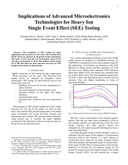
Fig. 1 shows representative Galactic Cosmic Ray (GCR)<br />
energy spectra as modeled by CREME96 software [5].<br />
CREME96 is considered to be the best available model for<br />
this application. Its limitations are discussed in [6]. GCR<br />
Particles are always present, but their intensities vary with<br />
the solar cycle. During solar minimum, GCR intensities<br />
attain their highest levels and during solar maximum they<br />
are at their lowest levels. The most important characteristic<br />
of GCRs is their very high energy (up to several GeV per<br />
nucleon). They are highly penetrating in terms of<br />
spacecraft shielding.<br />
Flux (#/cm 2 -s-MeV/n)<br />
1.E-02<br />
1.E-03<br />
1.E-04<br />
1.E-05<br />
1.E-06<br />
1.E-07<br />
1.E-08<br />
1.E-09<br />
100 mils, SOLMIN<br />
1.E-10<br />
1.E-01 1.E+00 1.E+01 1.E+02 1.E+03 1.E+04 1.E+05<br />
C<br />
Mg<br />
Fe<br />
Energy (MeV/nucleon)<br />
Fig. 1: Representative Cosmic Ray energy spectra, CREME 96 solmin.<br />
The Fig. 2 shows representative solar energetic particle<br />
spectra. Note the very large fluxes (compared to GCR) at<br />
low energies and the very rapid decrease of the flux with<br />
energy. Because the solar particle spectra are<br />
comparatively soft, typical spacecraft shielding does have a<br />
more noticeable effect.<br />
Ion beams dissipate energy in matter through a series of<br />
collisions with the atoms of the material. In microcircuits<br />
ionization leads to the creation of a dense plasma of<br />
electron-hole pairs along the ion track. Existing electric<br />
fields then transport the deposited charge to various nodes.<br />
In the study of <strong>SEE</strong> effects in microcircuits, it has become<br />
customary to describe the ion radiation quality by the<br />
amount of energy lost per unit length of track, or the Linear<br />
Energy Transfer (LET). As each material has a unique<br />
H<br />
He<br />
1
ionization potential, the LET is easily converted to a<br />
charge deposition rate. For example, in silicon, a charge<br />
deposition rate of 1 pC/μm corresponds to a LET of 98<br />
MeV/(mg/cm 2 ).<br />
Flux(#/cm 2 -s-MeV/n)<br />
1.E+04<br />
1.E+03<br />
1.E+02<br />
1.E+01<br />
1.E+00<br />
1.E-01<br />
1.E-02<br />
1.E-03<br />
1.E-04<br />
1.E-05<br />
1.E-06<br />
1.E-07<br />
1.E-08<br />
Fe<br />
GCR He<br />
100 mils Al shielding<br />
He<br />
C<br />
Mg<br />
H<br />
1.E-09<br />
1.E-01 1.E+00 1.E+01 1.E+02 1.E+03 1.E+04 1.E+05<br />
Energy (MeV/nucleon)<br />
Figure 2: The energy spectra of solar energetic<br />
particles, CREME96 worst day. The spectrum of cosmic ray Helium is<br />
showed for comparison.<br />
It is possible to obtain the same LET for different types<br />
of ions and energies. However, if it is assumed that all ions<br />
of a given LET have the same effect on the circuit, a LET<br />
spectrum can be used to estimate the upset rates in space.<br />
Such a characterization is called a Heinrich spectrum [7].<br />
Flux(#/cm 2 -s)<br />
1.E-01<br />
1.E-02<br />
1.E-03<br />
1.E-04<br />
1.E-05<br />
1.E-06<br />
1.E-07<br />
1.E-08<br />
1.E-09<br />
1.E-10<br />
1.E-11<br />
1.E-12<br />
Fe<br />
1.E-13<br />
1.E-14<br />
100 mils Al shielding<br />
1.E-01 1.E+00 1.E+01 1.E+02<br />
LET (MeVcm 2 /mg)<br />
Figure 3: GCR LET spectrum, CREME 96 solmin.<br />
H<br />
He<br />
Li<br />
Total Z=1 to 92<br />
The GCR integral LET spectrum for silicon is shown in<br />
Fig. 3 along with contributions of some individual species.<br />
The lightest ions are dominant in the lowest LET (0.1 to 1<br />
MeV/(mg/cm 2 )) part of the spectrum. The heaviest ions are<br />
dominant in the highest LET part (30 to 100<br />
MeV/(mg/cm 2 )). However, the fluences in this latter<br />
portion are very small. For LETs from 1 to 30<br />
MeV/(mg/cm 2 ), the LET spectrum is dominated by the Fe<br />
and Ni ions. The Solar Particle Event (SPE) integral LET<br />
spectrum is shown in Fig. 4. The lowest LET part of the<br />
spectrum is dominated by protons and alpha particles.<br />
Similar to GCR, the heaviest ions are dominant in the<br />
highest LET (> 30 MeV/(mg/cm 2 )) range of the spectrum,<br />
but their overall contribution is extremely small. In the<br />
U<br />
Au<br />
Ni<br />
Pb<br />
medium LET range (1 to 30 MeV/mg/cm 2 )), Fe is the most<br />
significant ion.<br />
Integral Flux (#/cm 2 -s)<br />
1.E+03<br />
1.E+02<br />
1.E+01<br />
1.E+00<br />
1.E-01<br />
1.E-02<br />
1.E-03<br />
1.E-04<br />
1.E-05<br />
1.E-06<br />
1.E-07<br />
1.E-08<br />
1.E-09<br />
1.E-10<br />
1.E-11<br />
1.E-12<br />
H<br />
He<br />
Fe<br />
Au<br />
Li<br />
U<br />
Pb<br />
Ni<br />
100 mils Al shielding<br />
total Z=1 to 92<br />
1.E-13<br />
1.E-01 1.E+00 1.E+01 1.E+02<br />
LET (MeVcm 2 /mg)<br />
Figure 4: SPE LET spectrum. CREME96 worst day.<br />
A plot of LET and range versus energy for Fe in silicon<br />
is shown in Fig. 5. We can see that the highest LET values<br />
correspond to the low to medium energy range (< 100<br />
MeV/u).<br />
LET (MeVcm 2 /mg)<br />
40<br />
30<br />
20<br />
10<br />
0<br />
10 -2<br />
10 -1<br />
10 0<br />
Fe in Silicon<br />
10 1<br />
Energy (MeV/u)<br />
Figure 5: LET and range in Silicon versus Energy, Fe ion.<br />
As the <strong>SEE</strong> sensitive regions of many microcircuits are<br />
relatively thin (several μm), ground testing is conducted<br />
using ions with lower energies than GCR, but with similar<br />
LET. The energy range at the <strong>SEE</strong> facilities commonly<br />
used [8,9,10,11] is of the order of several MeV/u and the<br />
range of ions is about from 30 μm for the heaviest particles<br />
to 100 μm for the lightest particles.<br />
The use of different angles of incidence is used to vary<br />
the energy deposition in the sensitive volume of a<br />
microcircuit and therefore obtain more experimental<br />
measurements with the same ion. This gives rise to the<br />
concept of effective LET, which assumes the energy<br />
deposition is determined by the incident particle’s LET and<br />
its angle of incidence. However, this does not account for<br />
several factors that may influence the measured results.<br />
First, this concept may not be valid for low energy ions<br />
because the LET value may decrease as the ions traverse<br />
the sensitive region. Secondly, the concept does not<br />
10 2<br />
10 3<br />
10 4<br />
2<br />
10 6<br />
10 5<br />
10 4<br />
10 3<br />
10 2<br />
10 1<br />
10 0<br />
range (um)
account for statistical fluctuations in the energy deposition<br />
process. Thirdly, it assumes that effects due to ion track<br />
structure are negligible. Quantitative estimates of these last<br />
two effects have been discussed in [12]. Finally, it assumes<br />
that the sensitive volume is a thin parallelepiped. Some<br />
<strong>SEE</strong>, such as SEB and SEGR cannot be correlated with tilt<br />
angle [13].<br />
When the GCR LET spectrum is defined and the SEU<br />
cross section curve versus LET is measured, the upset rate<br />
can then be calculated assuming a Rectangular<br />
Parallelepiped (RPP) sensitive volume and a constant LET<br />
in this sensitive volume [14].<br />
III. DISCUSSION AND EMERGING ISSUES<br />
As discussed in the preceding section, an incident ion’s<br />
LET is usually assumed to be a valid parameter for<br />
describing <strong>SEE</strong> effects in microcircuits. But in modern<br />
devices, sensitive volumes are very small and there may be<br />
a strong difference between the energy lost by the ion and<br />
the energy locally deposited in the sensitive volume. The<br />
ion LET (and effective LET) overestimates the energy<br />
deposition as shown in Fig. 6. This Figure shows the<br />
fraction of an ion’s energy loss as a function of the<br />
volume’s average chord length (ie the average travel length<br />
of the particles in the sensitive volume) for different<br />
incident ion energies [12]. We can see in the figure that the<br />
smaller is the sensitive volume and the higher is the ion<br />
energy, the higher is the overestimation. Then, charge<br />
collection is a complex phenomenon affected by the size of<br />
sensitive regions and the structural arrangements of<br />
multiple junctions. Therefore, it is controlled not only by<br />
the characteristics of the incident ions [15] but also by<br />
geometrical arrangement of junctions and the properties of<br />
the semiconductor material.<br />
Fion<br />
1<br />
0.9<br />
0.8<br />
0.7<br />
0.6<br />
0.3 1 3 10 30<br />
Curves labeled in MeV/u<br />
0.5<br />
0.001 0.01 0.1 1 10 100<br />
Average chord length (mm)<br />
Figure 6: fraction of an ion’s energy loss within the sensitive volume as a<br />
function of the volume’s average chord length for different incident ion<br />
energies [12].<br />
In addition, the use of low energy ions for <strong>SEE</strong> testing<br />
introduces experimental limitations: LET variations over<br />
the sensitive volume, low range inducing angle effects and<br />
limiting the funneling charge collection. Comparative <strong>SEE</strong><br />
100<br />
300<br />
1000<br />
testing studies with high and low energy ions have shown<br />
that standard low energy test methods were adequate to test<br />
previous generations of microcircuits (down to 0.5 μm<br />
feature size) [16, 17]. But, discrepancies have already been<br />
observed in high density microcircuits and vertical<br />
sensitive volumes like DRAMs [18,19].<br />
Another significant factor that must be considered for<br />
<strong>SEE</strong> testing of modern microcircuits is to use ions that<br />
reach the sensitive regions. Some devices can have up to 5<br />
metallization layers, and are constructed with a metal lead<br />
frame extending over the die. Others have the entire die<br />
encapsulated in plastic material [20]. Plastic removing<br />
techniques have been used with success for several years,<br />
but removing the lead frame of a DRAM is a much more<br />
complex operation. These factors have resulted in the need<br />
for ions with a longer range (ie of higher energy) to<br />
penetrate to sensitive regions through plastic, lead frames<br />
and/or metallization layers. It is not uncommon now to<br />
have to go through on the order of 100 μm of material<br />
before reaching the sensitive region of a device (for<br />
example the thickness of a lead frame on a 64M DRAM is<br />
about 150 µm). For certain types of devices such as flip<br />
chip devices, this thickness could be even greater. The<br />
heavy ion accelerators currently used for SEU testing can<br />
not deliver this range.<br />
Because of the complexities of the charge collection<br />
process and new package technologies in advanced<br />
microcircuits, it is becoming more and more necessary for<br />
<strong>SEE</strong> testing to use ions with an energy range representative<br />
of the <strong>SEE</strong> space environment.<br />
Fig. 7 shows the ratio of particles of low energy (0.1 to<br />
25 MeV/u), medium energy (25 to 200 MeV/u) and high<br />
energy (> 200 MeV/u) in the GCR LET spectrum. We can<br />
see in the Figure that high energy particles dominate the<br />
low LET part of the spectrum, but are negligible for LET<br />
greater than about 3 MeV/(mg/cm 2 ). The low energy<br />
particles, (the particles having similar energy range to<br />
those often used for <strong>SEE</strong> testing) dominate the high LET<br />
spectrum from about 10 MeV/(mg/cm 2 ) to 100<br />
MeV/(mg/cm 2 ). The medium energy particles dominate the<br />
LET spectrum from about 1 to 10 MeV/(mg/cm 2 ).<br />
fraction of the integral fluence<br />
1.1<br />
1.0<br />
0.9<br />
0.8<br />
0.7<br />
0.6<br />
0.5<br />
0.4<br />
0.3<br />
0.2<br />
0.1<br />
> 200 MeV/u<br />
25 to 200 MeV/u<br />
0.0<br />
0.1 1.0 10.0 100.0<br />
LET (MeVcm 2 /mg)<br />
0.1 to 25 MeV/u<br />
Figure 7: repartition of low, medium and high energy ions in the GCR<br />
LET spectrum.<br />
3
Above a LET of 10 MeV/(mg/cm 2 ), space heavy ions<br />
have low or medium energy, and their range is limited. For<br />
example, for the Fe ion, above a LET of 28<br />
MeV/(mg/cm 2 ), the energy is less than 1.6 MeV/u and the<br />
range in silicon is less than 18 μm. As can be seen in<br />
Figure 3, Fe dominates the GCR spectrum for LETs<br />
between 10 and 28 MeV/(mg/cm 2 ). This implies that most<br />
particles with LETs in this range that reach the sensitive<br />
structure have a limited penetration range, which turns out<br />
to be between 18 and 400 μm as shown in Fig. 5. This is<br />
consistent with the penetration range of particles used for<br />
ground testing for this LET range.<br />
The most significant part of the LET spectra for<br />
advanced microcircuits is the range between 0.1 to 10<br />
MeV/(mg/ cm 2 ). Most sensitive devices have a threshold<br />
LET less than 1 MeV/(mg/cm 2 ) and their cross section<br />
reaches the saturation before 10 MeV/(mg/cm 2 ). It has<br />
been shown that the threshold LET of microcircuits with<br />
sensitive volume dimensions less than micrometers has not<br />
changed significantly with the device scaling [2].<br />
Therefore, except for optoelectronic devices, we do not<br />
expect in the near future threshold LET lower than 0.1<br />
MeV/(mg/cm 2 ), which implies that <strong>SEE</strong> can be produced<br />
by direct ionization due to protons.<br />
Considering the incident particle energies, the most<br />
significant energy range is the medium energy range from<br />
tens of MeV/u to 200 MeV/u.<br />
Maximum energy (MeV/u)<br />
1000<br />
100<br />
10<br />
1<br />
0.1<br />
TAMU<br />
Fe<br />
GANIL<br />
200 MeV/u<br />
25 MeV/u<br />
0 10 20 30 40 50 60 70 80 90<br />
Particle atomic number<br />
Figure 8: available beams in facilities used for <strong>SEE</strong> testing.<br />
IPN<br />
LBL<br />
The Fig. 8 shows the maximum beam energies available<br />
in facilities used for <strong>SEE</strong> testing. We can see that the most<br />
currently used facilities (BNL, UCL, IPN) with a maximum<br />
beam energy lower than 10 MeV/u do not cover this energy<br />
range at all. LBL and TEXAS A&M facilities cover a part<br />
of this range. GANIL and MSU facilities give the best<br />
coverage of the medium energy range, but it is generally<br />
difficult and expensive to get some beam for <strong>SEE</strong> testing in<br />
these facilities.<br />
UCL<br />
BNL<br />
MSU<br />
IV. CONCLUSION<br />
We have reviewed how the <strong>SEE</strong> test environment relates<br />
to the real space environment. Low energy beams are not<br />
representative of the most significant part of the space<br />
environment for modern microcircuits. Medium energy<br />
beams are a better representation of the space <strong>SEE</strong><br />
environment, and they also give longer ranges to allow<br />
access to the sensitive volumes of modern devices. For<br />
these reasons medium energy beams are more and more<br />
necessary for <strong>SEE</strong> testing. These beams are not well<br />
covered in the existing facilities currently used for <strong>SEE</strong><br />
testing.<br />
V. REFERENCES<br />
[1] R. Koga, “Single Event Effect Ground test issues,” IEEE TNS, vol.<br />
43, n°2, 661-670, April 1996.<br />
[2] A. H. Johnston, “<strong>Radiation</strong> <strong>Effects</strong> in Advanced Microelectronics<br />
Technologies,” RADECS 1997 Proceedings, pp. 1-16.<br />
[3] E. G. Stassinopoulos, “Shortcomings in Ground <strong>Testing</strong>,<br />
Environment simulations, and Performance Predictions for Space<br />
Applications,” RADECS 1991 Proceedings, pp.3-16.<br />
[4] S. Duzellier, R. Ecoffet, “Recent Trends in Single Event Effect<br />
Ground <strong>Testing</strong>,” ,” IEEE TNS, vol. 43, n°2, pp. 671-677, April<br />
1996.<br />
[5] A.J. Tylka & al., “Single Event Upsets caused by Solar Energetic<br />
Heavy Ions,” ,IEEE TNS, NS43, pp. 2758, Dec. 1996.<br />
[6] J. Barth “Modeling Space <strong>Radiation</strong> Environment” 1997 IEEE<br />
NSREC short course.<br />
[7] W. Heinrich, “Calculation of LET Spectra of Heavy Cosmic Ray<br />
Nuclei at Various Absorber Depths”, <strong>Radiation</strong> <strong>Effects</strong>, vol. 34,<br />
pp.143-148, 1977.<br />
[8] E.G. Stassinopoulos & al. ,“SEU measurements at the BNL test<br />
facility,” Trans. Am. Nucl. Soc., vol. 62, pp. 230-232, 1990.<br />
[9] M.A. Mc Mahan, ‘<strong>Radiation</strong> <strong>Effects</strong> <strong>Testing</strong> at the 88 inch<br />
Cyclotron” RADECS 1999 proceedings, pp. 142-147.<br />
[10] G. Berger & al., “The Heavy Ion Irradiation Facility at CYCLONE-<br />
A dedicated <strong>SEE</strong> beam line,” 1996 IEEE NREC data workshop, pp.<br />
78-83.<br />
[11] M. Labrunee & al., “Heavy ion component test coordination,”<br />
RADECS 1991 proceedings, pp. 577-581.<br />
[12] M.A. Xapsos, “Applicability of LET to Single Events in<br />
Microelectronic Structures”, IEEE Trans. Nucl. Sci., vol. 39, pp.<br />
1613-1621, Dec. 1992.<br />
[13] D.K. Nichols & al., “update of Single Event failure in power<br />
MOSFETs,” IEEE NSREC 1996 dataworkshop, pp. 67-72.<br />
[14] J. C. Pickel, “Single Event <strong>Effects</strong> Rate Prediction,” IEEE Trans.<br />
Nucl. Sci., vol. 43, n°2, April 1996.<br />
[15] H. Dussault, “The effects of ion track structure in simulating Single<br />
Event Phenomena,”, Proceedings of RADECS 1993, pp. 509-516.<br />
[16] R. Koga & al., “Comparative SEU sensitivities to relativistic heavy<br />
ions,” IEEE TNS, vol. 45, n°6, pp. 2475-2482, 1998.<br />
[17] P.E. Dodd & al. “Impact of ion energy on Single event Upset,”<br />
IEEE TNS, vol. 45, n°6, pp. 2483-2491, 1998.<br />
[18] S. Duzellier & al. “<strong>SEE</strong> results using high energy ions,” IEEE<br />
TNS, vol. 42, n°6, pp. 1797-1802, 1995.<br />
[19] R. Ecoffet “Low LET cross section measurements using high<br />
energy carbon beam,” IEEE TNS, vol. 44, n°6, 1997.<br />
[20] R. Koga & al., “<strong>SEE</strong> sensitivity determination of high density<br />
DRAMs with limited range heavy ions,” IEEE NSREC 2000 data<br />
workshop, pp45-52.<br />
4