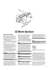
Inside the TT44 Manual, Part 2. Work Section and Valving
Inside the TT44 Manual, Part 2. Work Section and Valving
Inside the TT44 Manual, Part 2. Work Section and Valving

You also want an ePaper? Increase the reach of your titles
YUMPU automatically turns print PDFs into web optimized ePapers that Google loves.
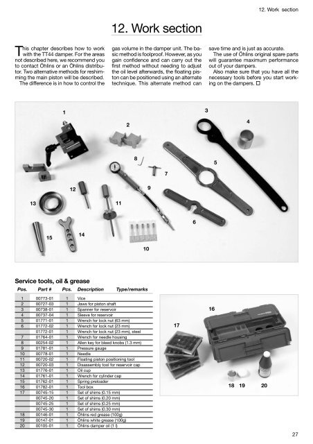
This chapter describes how to work<br />
with <strong>the</strong> <strong>TT44</strong> damper. For <strong>the</strong> areas<br />
not described here, we recommend you<br />
to contact Öhlins or an Öhlins distributor.<br />
Two alternative methods for reshimming<br />
<strong>the</strong> main piston will be described.<br />
The difference is in how to control <strong>the</strong><br />
13<br />
15<br />
12<br />
14<br />
Service tools, oil & grease<br />
1<br />
Pos. <strong>Part</strong> # Pcs. Description Type/remarks<br />
1 00773-01 1 Vice<br />
2 00727-03 1 Jaws for piston shaft<br />
3 00738-01 1 Spanner for reservoir<br />
4 00737-04 1 Sleeve for reservoir<br />
5 01771-01 1 Wrench for lock nut (63 mm)<br />
6 01772-02 1 Wrench for lock nut (23 mm)<br />
01772-01 1 Wrench for lock nut (23 mm), steel<br />
7 01764-01 1 Wrench for needle housing<br />
8 00254-02 1 Allen key for bleed knobs (1.3 mm)<br />
9 01781-01 1 Pressure gauge<br />
10 00778-01 1 Needle<br />
11 00720-02 1 Floating piston positioning tool<br />
12 00720-03 1 Disassembly tool for reservoir cap<br />
13 01776-01 1 Oil cup<br />
14 01761-01 1 Wrench for cylinder cap<br />
15 01762-01 1 Spring preloader<br />
16 01782-01 1 Tool box<br />
17 00745-15 1 Set of shims (0.15 mm)<br />
00745-20 1 Set of shims (0.20 mm)<br />
00745-25 1 Set of shims (0.25 mm)<br />
00745-30 1 Set of shims (0.30 mm)<br />
18 00146-01 1 Öhlins red grease (100g)<br />
19 00147-01 1 Öhlins white grease (100g)<br />
20 00105-01 1 Öhlins damper oil (1 l)<br />
1<strong>2.</strong> <strong>Work</strong> section<br />
gas volume in <strong>the</strong> damper unit. The basic<br />
method is foolproof. However, as you<br />
gain confidence <strong>and</strong> can carry out <strong>the</strong><br />
first method without needing to adjust<br />
<strong>the</strong> oil level afterwards, <strong>the</strong> floating piston<br />
can be positioned using an alternate<br />
technique. This alternate method can<br />
11<br />
2<br />
8<br />
10<br />
9<br />
7<br />
17<br />
6<br />
3<br />
1<strong>2.</strong> <strong>Work</strong> section<br />
save time <strong>and</strong> is just as accurate.<br />
The use of Öhlins original spare parts<br />
will guarantee maximum performance<br />
out of your dampers.<br />
Also make sure that you have all <strong>the</strong><br />
necessary tools before you start working<br />
on <strong>the</strong> dampers. <br />
16<br />
5<br />
4<br />
18 19 20<br />
27
1<strong>2.</strong> <strong>Work</strong> section / Main piston reshimming<br />
28<br />
A<br />
B<br />
Main piston reshimming,<br />
basic method<br />
Disassembly<br />
Caution!<br />
Before starting <strong>the</strong> reshimming<br />
procedure, it is of <strong>the</strong> utmost importance<br />
that <strong>the</strong> work area is<br />
completely clean <strong>and</strong> free from<br />
dust <strong>and</strong> dirt.<br />
Contamination is <strong>the</strong> primary<br />
enemy of dampers. Do not use<br />
any shop rags around internal<br />
damper parts because lint will find<br />
its way inside <strong>the</strong> assembled<br />
damper. Öhlins recommends lintfree<br />
paper only.<br />
✓ Mount <strong>the</strong> body eye in a vice<br />
with soft jaws or use Öhlins vice<br />
(part # 00773-01).<br />
✓ Remove <strong>the</strong> screw <strong>and</strong> O-ring<br />
from <strong>the</strong> reservoir end cap<br />
whe<strong>the</strong>r piggyback or remote<br />
style.<br />
Use Öhlins needle system (part<br />
#01781-01) to depressurize <strong>the</strong><br />
damper.<br />
WARNING<br />
Releasing high-pressure gas can<br />
be hazardous. Never perform any<br />
service until <strong>the</strong> gas pressure has<br />
been released from <strong>the</strong> damper.<br />
✓ Make sure that <strong>the</strong> needle is undamaged<br />
by checking for burrs<br />
around <strong>the</strong> sharp tip.<br />
✓ Apply some Öhlins red grease<br />
(part #00146-01) to <strong>the</strong> tip before<br />
inserting it into <strong>the</strong> rubber membrane<br />
in <strong>the</strong> reservoir end cap.<br />
✓ Insert <strong>the</strong> needle near <strong>the</strong> center<br />
of <strong>the</strong> rubber <strong>and</strong> parallel with <strong>the</strong><br />
axis of <strong>the</strong> reservoir.<br />
C<br />
D<br />
E
Caution!<br />
If <strong>the</strong> needle goes in part way <strong>and</strong><br />
stops it means <strong>the</strong> needle was not<br />
parallel <strong>and</strong> has collided with <strong>the</strong><br />
membrane housing. When this<br />
happens <strong>the</strong>re is a risk that <strong>the</strong> tip<br />
of <strong>the</strong> needle will be damaged.<br />
✓ When <strong>the</strong> needle is successfully<br />
inserted, thread <strong>the</strong> needle housing<br />
into <strong>the</strong> reservoir end cap.<br />
✓ Attach <strong>the</strong> quick-connect hose<br />
without <strong>the</strong> gauge to vent <strong>the</strong><br />
damper.<br />
✓ Remove <strong>the</strong> needle housing<br />
<strong>and</strong> connector hose.<br />
✓ Push <strong>the</strong> reservoir end cap<br />
down with your fingers <strong>and</strong> remove<br />
<strong>the</strong> circlip.<br />
This should be done by pushing<br />
<strong>the</strong> mid part of <strong>the</strong> circlip down<br />
into <strong>the</strong> reservoir so <strong>the</strong> sharp<br />
ends of <strong>the</strong> circlip swing up. If <strong>the</strong><br />
sharp ends of <strong>the</strong> circlip are<br />
pushed down into <strong>the</strong> reservoir or<br />
if a tool is used, <strong>the</strong> inside wall of<br />
<strong>the</strong> reservoir may be damaged.<br />
This can cause a nitrogen leak.<br />
If <strong>the</strong> reservoir end cap is stuck,<br />
install <strong>the</strong> removal tool (part #<br />
00720-03) shown in <strong>the</strong> next<br />
photo <strong>and</strong> tap <strong>the</strong> end of it with a<br />
soft mallet. Once it is dislodged<br />
<strong>the</strong> circlip can be removed as described<br />
above.<br />
F<br />
G<br />
H<br />
1<strong>2.</strong> <strong>Work</strong> section / Main piston reshimming<br />
✓ Insert <strong>the</strong> special removal tool<br />
(part # 00720-03) by threading it<br />
into <strong>the</strong> reservoir end cap.<br />
✓ Pull straight up with a slight wiggling<br />
motion to remove <strong>the</strong> cap.<br />
✓ Turn <strong>the</strong> bleed adjusters on <strong>the</strong><br />
damper body to fully open <strong>and</strong><br />
close <strong>the</strong> reservoir bleed.<br />
The open rebound bleed will make<br />
it easier to remove <strong>the</strong> shaft-piston<br />
assembly from <strong>the</strong> body. The<br />
open compression bleed will<br />
make it easier to reinstall <strong>the</strong> assembly<br />
later on. The closed reservoir<br />
bleed will reduce <strong>the</strong><br />
amount of oil leaking into <strong>the</strong> reservoir<br />
when installing <strong>and</strong> bleeding<br />
<strong>the</strong> piston.<br />
✓ If <strong>the</strong> oil cup (part # 01776-01)<br />
is used to avoid spillage, slide it<br />
onto <strong>the</strong> top of <strong>the</strong> damper body<br />
now.<br />
✓ By using Öhlins special wrench<br />
(part # 01761-01) unscrew <strong>the</strong><br />
cylinder cap.<br />
29
1<strong>2.</strong> <strong>Work</strong> section / Main piston reshimming<br />
30<br />
Groove<br />
I<br />
J<br />
✓ Carefully pull <strong>the</strong> shaft assembly<br />
out of <strong>the</strong> body.<br />
Do not pull too aggressively, as<br />
this will aerate <strong>the</strong> oil.<br />
If <strong>the</strong> shaft assembly resists coming<br />
out of damper, you probably<br />
forgot to open <strong>the</strong> rebound bleed<br />
adjuster.<br />
✓ Wipe <strong>the</strong> oil from <strong>the</strong> shaft assembly<br />
<strong>and</strong> mount it vertically in<br />
ei<strong>the</strong>r <strong>the</strong> Öhlins vice or <strong>the</strong> special<br />
shaft jaws (part #00727-03).<br />
If you remove <strong>the</strong> ball joint spacers<br />
<strong>the</strong> end eye can be clamped in a<br />
normal vice with soft jaws.<br />
✓ Unscrew <strong>the</strong> nut from <strong>the</strong> end<br />
of <strong>the</strong> shaft with a 17 mm wrench.<br />
✓ Remove <strong>the</strong> old rebound shims,<br />
piston <strong>and</strong> compression shims.<br />
Assembly<br />
Caution!<br />
The face of one side of <strong>the</strong> piston<br />
has a circular groove machined into<br />
it to identify <strong>the</strong> side of <strong>the</strong> rebound<br />
stack. This side of <strong>the</strong> piston <strong>and</strong><br />
<strong>the</strong> side of <strong>the</strong> rebound valve stop<br />
(part # 00519-02) with <strong>the</strong> large<br />
chamfer on <strong>the</strong> center hole should<br />
face towards <strong>the</strong> lock nut.<br />
A<br />
B<br />
C
✓ Select, inspect <strong>and</strong> measure<br />
every shim to be used in <strong>the</strong> new<br />
stack.<br />
✓ Place every shim to be included<br />
in <strong>the</strong> stack on a line in <strong>the</strong> right<br />
order <strong>and</strong> make a final check.<br />
The piston is flat on both sides<br />
providing easy control of <strong>the</strong> condition<br />
of <strong>the</strong> sealing surfaces, just<br />
lightly lap <strong>the</strong> piston against some<br />
600 grit wet/dry paper on top of a<br />
surface plate.<br />
✓ Tighten <strong>the</strong> lock nut. Torque: 22<br />
lbs.ft. (30 Nm).<br />
Caution!<br />
Over torqueing can crush <strong>the</strong> valve<br />
stops <strong>and</strong>/or piston. This will compromise<br />
<strong>the</strong> repeatability normally<br />
enjoyed with Öhlins dampers.<br />
✓ Make sure <strong>the</strong> locking device<br />
in <strong>the</strong> lock nut is fully engaged on<br />
<strong>the</strong> threads.<br />
Adjust this by adding or subtracting<br />
washers (part # 00578-01)<br />
between <strong>the</strong> nut <strong>and</strong> <strong>the</strong> rebound<br />
valve stop. Always try to maximize<br />
<strong>the</strong> number of washers (part #<br />
00578-01) to minimize <strong>the</strong> risk of<br />
burrs caused by <strong>the</strong> looking device<br />
of <strong>the</strong> lock nut.<br />
✓ Add some oil into <strong>the</strong> damper<br />
body until <strong>the</strong> oil level is just above<br />
<strong>the</strong> inner tube.<br />
D<br />
E<br />
F<br />
1<strong>2.</strong> <strong>Work</strong> section / Main piston reshimming<br />
✓ Place <strong>the</strong> shaft assembly into<br />
<strong>the</strong> damper body at about a 45°<br />
angle to submerge <strong>the</strong> piston in<br />
<strong>the</strong> oil.<br />
✓ Turn <strong>the</strong> piston until <strong>the</strong> gap in<br />
<strong>the</strong> piston ring is visible near <strong>the</strong><br />
top (still submerged).<br />
✓ Slowly rotate <strong>the</strong> shaft back <strong>and</strong><br />
forth until all <strong>the</strong> bubbles have<br />
escaped from behind <strong>the</strong> piston<br />
ring.<br />
✓ Tip <strong>the</strong> shaft up to vertical <strong>and</strong><br />
ease <strong>the</strong> piston into <strong>the</strong> inner tube.<br />
✓ Aggressively push <strong>the</strong> shaft into<br />
<strong>the</strong> oil <strong>and</strong> slowly return it to it’s<br />
starting point near <strong>the</strong> top of <strong>the</strong><br />
inner tube.<br />
✓ Repeat this a few times until <strong>the</strong><br />
oil looks clear.<br />
✓ Close <strong>the</strong> compression adjuster<br />
on <strong>the</strong> damper body.<br />
The closed compression bleed<br />
<strong>and</strong> reservoir bleed (already<br />
closed) will make it easier to release<br />
<strong>the</strong> trapped air in <strong>the</strong> piston.<br />
31
1<strong>2.</strong> <strong>Work</strong> section / Main piston reshimming<br />
32<br />
G ✓<br />
H<br />
I<br />
Tap briskly on <strong>the</strong> shaft end eye<br />
a few times with a plastic mallet<br />
to force <strong>the</strong> submerged compression<br />
shims to open <strong>and</strong> release<br />
<strong>the</strong> air trapped in <strong>the</strong> piston.<br />
Caution!<br />
Be sure to hold <strong>the</strong> shaft assembly<br />
in line with <strong>the</strong> damper body,<br />
so as not to damage <strong>the</strong> inner<br />
tube.<br />
✓ Screw <strong>the</strong> special positioning<br />
tool (part #00720-02) into <strong>the</strong> reservoir<br />
floating piston.<br />
✓ Loosen <strong>the</strong> thumbscrew on <strong>the</strong><br />
sliding plate.<br />
✓ Push <strong>the</strong> positioning tool down<br />
forcing <strong>the</strong> floating piston all <strong>the</strong><br />
way to <strong>the</strong> bottom of <strong>the</strong> reservoir.<br />
✓ Move <strong>the</strong> sliding plate down<br />
against <strong>the</strong> reservoir tube <strong>and</strong> lock<br />
it with <strong>the</strong> thumbscrew.<br />
J<br />
K<br />
L
✓ Open <strong>the</strong> compression <strong>and</strong> reservoir<br />
adjusters completely.<br />
✓ Position <strong>the</strong> piston at <strong>the</strong> top of<br />
<strong>the</strong> inner tube.<br />
✓ Add more oil until you can<br />
scrape <strong>the</strong> remaining bubbles<br />
over <strong>the</strong> edge of <strong>the</strong> top of <strong>the</strong><br />
body.<br />
✓ Rotate <strong>the</strong> cylinder cap slowly<br />
(to prevent sticking), as you slide<br />
it down <strong>the</strong> shaft until it touches<br />
<strong>the</strong> compression valve stop (with<br />
<strong>the</strong> piston still at <strong>the</strong> top of <strong>the</strong> inner<br />
tube).<br />
✓ Gently push <strong>the</strong> piston, shaft<br />
<strong>and</strong> cylinder cap as a unit into <strong>the</strong><br />
body until <strong>the</strong> cap stops. This<br />
leaves about two threads showing<br />
before <strong>the</strong> O-ring engages <strong>the</strong><br />
body.<br />
If <strong>the</strong> oil overflowing from <strong>the</strong> cap<br />
during this step does not appear<br />
clear, <strong>the</strong>n this step must be repeated<br />
after more oil has been<br />
added in <strong>the</strong> body.<br />
✓ Screw <strong>the</strong> cylinder cap into <strong>the</strong><br />
body <strong>and</strong> tighten it. Torque: 22<br />
lbs.ft. (30 Nm).<br />
Once <strong>the</strong> cylinder cap O-ring seals<br />
<strong>the</strong> body, <strong>the</strong> rest of <strong>the</strong> tightening<br />
will cause <strong>the</strong> volume of <strong>the</strong><br />
cap to displace some oil into <strong>the</strong><br />
reservoir.<br />
M<br />
N<br />
O<br />
1<strong>2.</strong> <strong>Work</strong> section / Main piston reshimming<br />
The positioning tool has moved<br />
out of <strong>the</strong> reservoir in proportion<br />
to <strong>the</strong> displaced oil.<br />
✓ Measure <strong>the</strong> distance between<br />
<strong>the</strong> reservoir body <strong>and</strong> <strong>the</strong> sliding<br />
plate on <strong>the</strong> positioning tool.<br />
✓ The gap should be between 4<br />
<strong>and</strong> 8 mm. This dimension is not<br />
critical as long as it is within this<br />
range.<br />
Note<br />
If <strong>the</strong> gap is within <strong>the</strong> tolerance,<br />
you can skip <strong>the</strong> text below <strong>and</strong><br />
go directly to step p. If <strong>the</strong> gap is<br />
out of tolerance, <strong>the</strong> oil volume is<br />
incorrect. The following text describes<br />
how to adjust <strong>the</strong> oil volume.<br />
More than 8 mm gap indicates<br />
that <strong>the</strong>re is too much oil in <strong>the</strong><br />
reservoir.<br />
If so:<br />
✓ Carefully loosen <strong>the</strong> small bleed<br />
screw on <strong>the</strong> reservoir, but do not<br />
remove it completely.<br />
✓ Pressurize <strong>the</strong> damper by pushing<br />
on <strong>the</strong> positioning tool until oil<br />
leaks out around <strong>the</strong> bleed screw.<br />
Continue pushing until <strong>the</strong> gap to<br />
<strong>the</strong> tool is about right.<br />
✓ Tighten <strong>the</strong> bleed screw without<br />
releasing pressure on <strong>the</strong> positioning<br />
tool.<br />
Less than 4 mm gap indicates that<br />
<strong>the</strong>re is too little oil in <strong>the</strong> reservoir.<br />
If so:<br />
✓ Remove <strong>the</strong> cylinder cap again.<br />
✓ Loosen <strong>the</strong> thumbscrew on <strong>the</strong><br />
sliding plate <strong>and</strong> push <strong>the</strong> reservoir<br />
floating piston all <strong>the</strong> way to<br />
<strong>the</strong> bottom.<br />
✓ With <strong>the</strong> thumbscrew lock <strong>the</strong><br />
sliding plate again.<br />
✓ With <strong>the</strong> tool, pull <strong>the</strong> floating<br />
piston slightly away from <strong>the</strong> bottom<br />
of <strong>the</strong> reservoir.<br />
✓ This will add some extra oil volume<br />
in <strong>the</strong> reservoir. Add oil to <strong>the</strong><br />
edge of <strong>the</strong> top of <strong>the</strong> body.<br />
✓ Repeat step K.<br />
33
1<strong>2.</strong> <strong>Work</strong> section / Main piston reshimming<br />
34<br />
P<br />
Q<br />
R<br />
✓ Unscrew <strong>the</strong> positioning tool<br />
from <strong>the</strong> floating piston.<br />
✓ Install <strong>the</strong> reservoir end cap <strong>and</strong><br />
circlip with your fingers. No tools<br />
are necessary <strong>and</strong> will only increase<br />
<strong>the</strong> risk of damage.<br />
✓ Insert <strong>the</strong> needle system again<br />
as described in step “Disassembly”<br />
B, <strong>and</strong> thread <strong>the</strong> needle<br />
housing into <strong>the</strong> reservoir end cap.<br />
✓ Attach <strong>the</strong> quick-connect hose,<br />
followed by <strong>the</strong> quick-connect<br />
gauge <strong>and</strong> charge <strong>the</strong> damper<br />
with nitrogen to <strong>the</strong> desired pressure,<br />
normally between 10 <strong>and</strong> 15<br />
bar (150 <strong>and</strong> 225 psi).<br />
WARNING<br />
Use of inflammable gas for pressuring<br />
<strong>the</strong> damper unit can be hazardous.<br />
Use nitrogen gas (N 2 ) only!<br />
✓ Disconnect <strong>the</strong> gauge <strong>and</strong> hose<br />
as a unit at <strong>the</strong> quick-connect<br />
coupling between <strong>the</strong> hose <strong>and</strong><br />
needle housing. If you disconnect<br />
<strong>the</strong> gauge only, <strong>the</strong> nitrogen will<br />
be free to escape.<br />
✓ Remove <strong>the</strong> oil cup.<br />
✓ Reinstall <strong>the</strong> screw <strong>and</strong> <strong>the</strong> Oring<br />
in <strong>the</strong> end cap to protect <strong>the</strong><br />
rubber membrane.<br />
✓ Set <strong>the</strong> adjusters to <strong>the</strong> desired<br />
clicker positions.
Main piston reshimming,<br />
alternate method<br />
Disassembly<br />
✓ Follow original steps A - B.<br />
However, on dampers where you<br />
are able to later on unscrew <strong>the</strong><br />
end cap of <strong>the</strong> damper body without<br />
removing <strong>the</strong> needle housing<br />
<strong>and</strong> connector hose, <strong>the</strong>y do not<br />
have to be removed after depressurizing<br />
<strong>the</strong> damper.<br />
✓ Skip steps C - F.<br />
✓ Follow steps G - J.<br />
Assembly<br />
✓ Follow steps A - G.<br />
✓ Reinstall <strong>the</strong> complete needle<br />
system <strong>and</strong> charge <strong>the</strong> reservoir<br />
enough to force <strong>the</strong> floating piston<br />
to <strong>the</strong> bottom of <strong>the</strong> reservoir.<br />
You should see <strong>the</strong> oil level in <strong>the</strong><br />
body rise a small distance. If <strong>the</strong><br />
oil does not rise do not worry.<br />
Sometimes <strong>the</strong> floating piston will<br />
be pulled to <strong>the</strong> bottom just from<br />
<strong>the</strong> vacuum created when <strong>the</strong><br />
shaft assembly is removed from<br />
<strong>the</strong> body.<br />
✓ Release <strong>the</strong> nitrogen by disconnecting<br />
<strong>the</strong> gauge from <strong>the</strong> hose,<br />
or if necessary later on to be able<br />
to mount <strong>the</strong> end cup of <strong>the</strong><br />
damper body, remove <strong>the</strong> whole<br />
gauge assembly.<br />
An air gun can normally do <strong>the</strong><br />
same job by just blowing pressurized<br />
air directly into <strong>the</strong> quickconnect<br />
hose. To get <strong>the</strong> pressure<br />
needed, use compressed air of at<br />
least 6 bar (90 psi) <strong>and</strong> make sure<br />
you have no major leak between<br />
<strong>the</strong> airgun <strong>and</strong> <strong>the</strong> hose.<br />
✓ Skip steps H <strong>and</strong> I.<br />
✓ Follow steps J - L.<br />
✓ Skip steps M - P.<br />
✓ Follow steps Q - R.<br />
A<br />
B<br />
C<br />
1<strong>2.</strong> <strong>Work</strong> section / Reservoir reshimming<br />
Reservoir reshimming<br />
Disassembly<br />
✓ Release <strong>the</strong> nitrogen pressure<br />
from <strong>the</strong> reservoir using <strong>the</strong> needle<br />
system.<br />
See section “Disassembly” in<br />
chapter “Main piston reshimming,<br />
basic method”, on page 28, for<br />
more details about how to depressurize<br />
<strong>the</strong> unit. The needle housing<br />
<strong>and</strong> quick-connect hose do<br />
not have to be removed from <strong>the</strong><br />
reservoir after depressurizing.<br />
✓ With <strong>the</strong> black reservoir knob<br />
pointing upwards, gently grip <strong>the</strong><br />
reservoir in a vice with soft jaws.<br />
Note<br />
Mount <strong>the</strong> damper in <strong>the</strong> vice so<br />
<strong>the</strong> body contacts <strong>the</strong> side of <strong>the</strong><br />
vice jaws. This will help keep <strong>the</strong><br />
body from rotating when you<br />
loosen <strong>the</strong> reservoir end piece.<br />
✓ Turn <strong>the</strong> black knob counterclockwise<br />
to fully open.<br />
By opening <strong>the</strong> reservoir adjuster<br />
<strong>the</strong>re is no risk of bruising <strong>the</strong> needle<br />
seat bolt when later on tightening<br />
<strong>the</strong> end piece.<br />
✓ Remove <strong>the</strong> small Phillips screw<br />
from <strong>the</strong> center of <strong>the</strong> knob <strong>and</strong><br />
lift off <strong>the</strong> knob.<br />
✓ Before removing <strong>the</strong> end piece,<br />
wipe away all dirt from around this<br />
area.<br />
✓ With a 17 mm wrench remove<br />
<strong>the</strong> reservoir end piece.<br />
✓ Before you lift out <strong>the</strong> valve<br />
body, add enough oil to <strong>the</strong> open<br />
valve cavity to make sure <strong>the</strong> passageway<br />
to <strong>the</strong> main body is always<br />
covered with oil.<br />
By adding oil, air is prevented from<br />
entering <strong>the</strong> main body while you<br />
remove <strong>the</strong> valve body.<br />
35
1<strong>2.</strong> <strong>Work</strong> section / Reservoir reshimming<br />
36<br />
D<br />
E<br />
✓ With some small pliers reach<br />
into <strong>the</strong> oil <strong>and</strong> grip <strong>the</strong> valve by<br />
<strong>the</strong> two flats near <strong>the</strong> center <strong>and</strong><br />
lift out <strong>the</strong> valve.<br />
This can also be achieved with a<br />
small screwdriver at a slight angle<br />
<strong>and</strong> some side pressure on <strong>the</strong><br />
inside of <strong>the</strong> cup that covers <strong>the</strong><br />
check valve. Maintaining <strong>the</strong> side<br />
pressure, slowly pull straight up<br />
until <strong>the</strong> valve is out.<br />
✓ Unscrew <strong>the</strong> needle seat bolt<br />
<strong>and</strong> disassemble <strong>the</strong> valve.<br />
Use a 13 mm wrench on <strong>the</strong> needle<br />
seat bolt <strong>and</strong> an 8 mm wrench<br />
on <strong>the</strong> flats on <strong>the</strong> valve body. Position<br />
<strong>the</strong> wrenches so both can<br />
be squeezed by one h<strong>and</strong> to<br />
loosen <strong>the</strong> needle seat bolt. With<br />
<strong>the</strong> thumb <strong>and</strong> forefinger of your<br />
o<strong>the</strong>r h<strong>and</strong> squeeze both sides of<br />
<strong>the</strong> valve assembly so <strong>the</strong> wrenches<br />
will not jump off.<br />
Optional technique to<br />
secure <strong>the</strong> seat condition<br />
This step is of importance only if<br />
you suspect damage or if you are<br />
unsure about <strong>the</strong> seat condition.<br />
✓ Using a figure-eight motion<br />
F lightly lap <strong>the</strong> valve piston seat<br />
A<br />
against some 600 grit wet/dry paper<br />
on top of a surface plate.<br />
Lap just enough to remove <strong>the</strong><br />
black oxide coating but no more.<br />
✓ Wash <strong>the</strong> valve with brake<br />
cleaner or solvent <strong>and</strong> dry it with<br />
an air hose.<br />
This procedure is a good idea<br />
even with br<strong>and</strong>-new parts.<br />
✓ After it is dry shake <strong>the</strong> valve<br />
<strong>and</strong> listen for any rattling of <strong>the</strong><br />
one-way check valve.<br />
Rattling indicates that <strong>the</strong> wave<br />
washer return spring has deformed<br />
permanently. If it rattles it<br />
should be replaced or dismantled<br />
<strong>and</strong> repaired.
Optional matching<br />
technique<br />
This technique will give a smaller<br />
tolerance of <strong>the</strong> shim stack preload,<br />
making it easier to match<br />
dampers.<br />
✓ Lap <strong>the</strong> valve bodies, using a<br />
figure-eight motion, against some<br />
600 grit wet/dry paper on top of a<br />
surface plate so <strong>the</strong>y will end up<br />
having <strong>the</strong> same offset between<br />
<strong>the</strong> sealing seat <strong>and</strong> <strong>the</strong> center<br />
l<strong>and</strong> where <strong>the</strong> preload shims are<br />
clamped.<br />
We suggest you rotate <strong>the</strong> valve<br />
body in relation to your fingers<br />
every few figure-eight movements.<br />
Nominally this offset is 0.40 mm.<br />
Sometimes <strong>the</strong> offset is more like<br />
0.4<strong>2.</strong><br />
Note<br />
The offset can be checked with a<br />
depth micrometer resting on <strong>the</strong><br />
valve seat <strong>and</strong> measuring down to<br />
<strong>the</strong> center l<strong>and</strong>. It is not so important<br />
to lap <strong>the</strong> valves down to <strong>the</strong><br />
nominal 0.40 as it is to make <strong>the</strong>m<br />
all <strong>the</strong> same.<br />
Assembly<br />
✓ Select, inspect <strong>and</strong> measure<br />
every shim to be used in <strong>the</strong> new<br />
stack.<br />
✓ Place every shim to be included<br />
in <strong>the</strong> stack on a line in <strong>the</strong> right<br />
order <strong>and</strong> make a final check.<br />
✓ Mount <strong>the</strong> stepped washer on<br />
<strong>the</strong> needle seat bolt.<br />
The stepped washer should be<br />
mounted in <strong>the</strong> direction of <strong>the</strong><br />
smaller o.d. (10 mm) pointing upwards<br />
against <strong>the</strong> shim stack.<br />
✓ Mount <strong>the</strong> stack on <strong>the</strong> bolt.<br />
The last shim is always of type o.d.<br />
12 mm to reduce <strong>the</strong> preload.<br />
B<br />
C<br />
D<br />
1<strong>2.</strong> <strong>Work</strong> section / Reservoir reshimming<br />
✓ Assemble <strong>the</strong> valve body <strong>and</strong><br />
<strong>the</strong> needle seat bolt upside down<br />
to keep <strong>the</strong> shims from falling off<br />
<strong>the</strong> shoulders of <strong>the</strong> bolt.<br />
✓ Tighten <strong>the</strong> two parts toge<strong>the</strong>r.<br />
Torque: 4.5 lbs.ft. (6 Nm).<br />
Optional matching<br />
technique<br />
This technique is intended to allow<br />
<strong>the</strong> needle to align <strong>the</strong> valve<br />
assembly when <strong>the</strong> end piece is<br />
tightened. By using this technique<br />
<strong>the</strong> risk of <strong>the</strong> needle getting<br />
rubbed by <strong>the</strong> needle seat bolt at<br />
low click positions numbers is reduced.<br />
Also when it comes to<br />
matching dampers some improvements<br />
can be made.<br />
✓ Hold <strong>the</strong> end piece <strong>and</strong> valve<br />
body toge<strong>the</strong>r exactly like <strong>the</strong>y will<br />
be oriented when installed.<br />
✓ Close <strong>the</strong> adjuster until <strong>the</strong> needle<br />
is pushing <strong>the</strong> two pieces<br />
apart.<br />
✓ Go back one click <strong>and</strong> <strong>the</strong> two<br />
pieces will again touch each o<strong>the</strong>r.<br />
Caution!<br />
If <strong>the</strong> needle is closed too far <strong>the</strong><br />
needle <strong>and</strong> <strong>the</strong> needle seat bolt<br />
will be broached as <strong>the</strong> end piece<br />
is tightened.<br />
The parts are now ready for installation.<br />
✓ Drop <strong>the</strong> valve assembly into<br />
<strong>the</strong> reservoir cavity.<br />
✓ When <strong>the</strong> valve is aligned with<br />
its bore, <strong>and</strong> with a blunt punch<br />
covering <strong>the</strong> center bleed orifice,<br />
push it to its seat as quickly as<br />
possible. This will open <strong>the</strong> return<br />
check-valve <strong>and</strong> release some<br />
trapped air.<br />
✓ Before installing <strong>the</strong> end piece,<br />
wrap a paper towel around <strong>the</strong><br />
perimeter of <strong>the</strong> cavity, as <strong>the</strong>re<br />
will be some oil overflow.<br />
✓ Add some oil if necessary to<br />
guarantee oil overflow to purge<br />
trapped air.<br />
✓ Now thread in <strong>the</strong> end piece <strong>and</strong><br />
tighten it. Torque: 12 lbs.ft. (18<br />
Nm).<br />
37
1<strong>2.</strong> <strong>Work</strong> section / Reservoir reshimming<br />
38<br />
Optional matching<br />
technique<br />
This technique is intended to better<br />
match dampers with <strong>the</strong> same<br />
clicker settings.<br />
✓ Before tightening <strong>the</strong> end piece,<br />
check to make sure <strong>the</strong> adjuster<br />
needle is free.<br />
✓ Continue tightening little by little<br />
to verify <strong>the</strong> needle is still free.<br />
✓ As you do this, check to see<br />
how close <strong>the</strong> first click position<br />
is to fully closed. Within reason,<br />
<strong>the</strong> more <strong>the</strong> cap is tightened <strong>the</strong><br />
closer <strong>the</strong> first click will be to fully<br />
closed.<br />
However, since <strong>the</strong> torque should<br />
not vary too much from 12 lbs.ft.,<br />
it should be in <strong>the</strong> range of 9-15<br />
lbs.ft. (12-20 Nm), this method has<br />
some limits.<br />
✓ Reinstall black knob with <strong>the</strong><br />
small Phillips screw.<br />
✓ Insert needle refill system <strong>and</strong><br />
recharge with nitrogen. See section<br />
“Assembly” in chapter “Main<br />
piston reshimming, basic method”<br />
for more details about how to<br />
pressurize <strong>the</strong> unit.<br />
✓ Reinstall <strong>the</strong> screw <strong>and</strong> O-ring<br />
to protect <strong>the</strong> rubber membrane.<br />
HSC adjuster installation<br />
The HSC adjuster is normally sold<br />
as a separate kit. This means that<br />
<strong>the</strong> customer or <strong>the</strong> distributor will<br />
install it. If you plan to do it yourself,<br />
<strong>the</strong> following text gives guidance.<br />
Two different springs are available<br />
<strong>and</strong> <strong>the</strong>refore a short separate<br />
section is included on how to do<br />
a spring change.<br />
A<br />
B<br />
C
Disassembly<br />
✓ Disassemble <strong>the</strong> damper as if<br />
you intend to make a st<strong>and</strong>ard<br />
valving change. See “Main piston<br />
reshimming” on page 28.<br />
✓ Remove <strong>the</strong> compression valve<br />
stop, <strong>the</strong> internal travel limiting<br />
spacers (if any) <strong>and</strong> <strong>the</strong> end cap<br />
as a unit.<br />
✓ Compare <strong>the</strong> new <strong>and</strong> <strong>the</strong> old<br />
parts to check that lengths match.<br />
✓ Mount <strong>the</strong> new HSC adjuster<br />
end eye in a vice with <strong>the</strong> shaft<br />
pointing upwards.<br />
✓ Loosen <strong>the</strong> lock nut with <strong>the</strong><br />
special 23 mm wrench (part #<br />
01772-02).<br />
✓ Remove <strong>the</strong> end eye from <strong>the</strong><br />
shaft.<br />
✓ Hold <strong>the</strong> HSC adjuster shaft with<br />
<strong>the</strong> special clamp blocks (part #<br />
00727-03) in a vice.<br />
✓ Loosen <strong>the</strong> hex on <strong>the</strong> adjuster<br />
seal cap with a 10 mm wrench.<br />
You may have to turn <strong>the</strong> adjuster<br />
wheel clockwise (reverse thread)<br />
to make room for <strong>the</strong> wrench.<br />
✓ Remove <strong>the</strong> entire adjuster assembly<br />
mechanism.<br />
Be careful not to lose <strong>the</strong> cross<br />
pin found at <strong>the</strong> bottom of <strong>the</strong><br />
adjuster assembly. If <strong>the</strong> cross pin<br />
does fall out it can be reinstalled<br />
in any hole, as <strong>the</strong>re is no indexing<br />
of <strong>the</strong> pin.<br />
D<br />
A<br />
B<br />
1<strong>2.</strong> <strong>Work</strong> section / HSC adjuster installation<br />
✓ Turn <strong>the</strong> shaft upside down <strong>and</strong><br />
tap <strong>the</strong> shaft lightly on <strong>the</strong> bench<br />
to remove <strong>the</strong> spring, <strong>the</strong> poppet<br />
valve <strong>and</strong> <strong>the</strong> bronze bushing.<br />
The valve seat does not need to<br />
be removed from <strong>the</strong> shaft.<br />
✓ Wash all parts thoroughly even<br />
though <strong>the</strong>y are new <strong>and</strong> make<br />
sure <strong>the</strong>y are internally <strong>and</strong> externally<br />
clean.<br />
Assembly<br />
✓ Reinstall <strong>the</strong> bronze bushing by<br />
dropping it into <strong>the</strong> shaft.<br />
✓ Look for <strong>the</strong> chamfer on one<br />
end of <strong>the</strong> bore. Install <strong>the</strong> bushing<br />
with <strong>the</strong> chamfer pointing towards<br />
<strong>the</strong> end of <strong>the</strong> end eye.<br />
✓ Install <strong>the</strong> poppet valve with <strong>the</strong><br />
flat end towards <strong>the</strong> piston.<br />
✓ Install <strong>the</strong> spring.<br />
✓ Lower <strong>the</strong> adjuster assembly<br />
mechanism into <strong>the</strong> shaft. It<br />
should go all <strong>the</strong> way down until<br />
<strong>the</strong> external O-ring of <strong>the</strong> seal cap<br />
reaches <strong>the</strong> end of <strong>the</strong> shaft. See<br />
<strong>the</strong> photo.<br />
Caution!<br />
If <strong>the</strong> seal cap sits higher, <strong>the</strong>re is<br />
a risk that <strong>the</strong> poppet valve, <strong>the</strong><br />
spring <strong>and</strong> <strong>the</strong> adjuster are misaligned.<br />
In that case, withdraw <strong>the</strong><br />
mechanism slightly <strong>and</strong> shake <strong>the</strong><br />
mechanism <strong>and</strong> <strong>the</strong> shaft until<br />
parts fall in place.<br />
✓ Tighten <strong>the</strong> seal cap loosely in<br />
<strong>the</strong> shaft.<br />
39
1<strong>2.</strong> <strong>Work</strong> section / HSC adjuster installation<br />
40<br />
C<br />
D<br />
E<br />
✓ Turn <strong>the</strong> adjuster wheel counterclockwise<br />
until it touches <strong>the</strong><br />
seal cap (as in <strong>the</strong> photo).<br />
The adjuster wheel is set by reaching<br />
in with a 2 mm pin through <strong>the</strong><br />
little aperture in <strong>the</strong> end eye, engage<br />
<strong>the</strong> holes on <strong>the</strong> perimeter<br />
of <strong>the</strong> adjuster wheel.<br />
Caution!<br />
If <strong>the</strong> adjuster wheel is not close to<br />
<strong>the</strong> seat cap, <strong>the</strong>re is a risk <strong>the</strong> adjuster<br />
mechanism will be crushed<br />
when installing <strong>the</strong> eye.<br />
✓ Install <strong>the</strong> end eye, but do not<br />
tighten it on <strong>the</strong> shaft, but do lock<br />
<strong>the</strong> end eye to <strong>the</strong> shaft with <strong>the</strong><br />
lock nut.<br />
✓ Reinstall <strong>the</strong> original parts from<br />
<strong>the</strong> 3-way adjuster shaft on <strong>the</strong><br />
HSC adjuster shaft in <strong>the</strong> reverse<br />
order: <strong>the</strong> end cap, <strong>the</strong> internal<br />
travel limiting spacers (if any), <strong>the</strong><br />
compression valve stop, <strong>the</strong> compression<br />
shim stack etc.<br />
Note<br />
The HSC adjuster will probably not<br />
be used toge<strong>the</strong>r with <strong>the</strong> original<br />
compression shim. In chapter<br />
“High speed compression adjuster”<br />
<strong>the</strong>re is a discussion about<br />
<strong>the</strong> various options to be considered<br />
for use in conjunction with<br />
<strong>the</strong> HSC adjuster.<br />
✓ Install <strong>the</strong> HSC adjuster shaft<br />
in <strong>the</strong> damper <strong>and</strong> tighten <strong>the</strong> end<br />
cap as on a conventional 3-way<br />
adjustable damper.<br />
Note<br />
It may not be possible to purge<br />
air from <strong>the</strong> piston by tapping on<br />
<strong>the</strong> end of <strong>the</strong> end eye with a soft<br />
mallet during assembly unless <strong>the</strong><br />
poppet valve is held closed. Turning<br />
<strong>the</strong> adjuster wheel several<br />
sweeps clockwise (if you view <strong>the</strong><br />
damper from <strong>the</strong> end of <strong>the</strong> end<br />
eye) does this. There are two clicks<br />
per sweep.<br />
Do not inflate <strong>the</strong> reservoir at this<br />
time.<br />
F<br />
G<br />
H
✓ Again remove <strong>the</strong> end eye.<br />
✓ Turn <strong>the</strong> adjuster wheel clockwise<br />
to make room for a wrench if<br />
necessary.<br />
✓ Loosen <strong>the</strong> seal cap of <strong>the</strong> HSC<br />
adjuster with a 10 mm wrench.<br />
It may be necessary to hold <strong>the</strong><br />
shaft in clamp blocks if <strong>the</strong> seal<br />
cap would not thread out without<br />
turning <strong>the</strong> shaft.<br />
✓ With <strong>the</strong> damper vertical in a<br />
vice, with <strong>the</strong> shaft upwards, remove<br />
<strong>the</strong> adjuster assembly<br />
mechanism. Do not remove <strong>the</strong><br />
spring <strong>and</strong> <strong>the</strong> poppet valve.<br />
✓ Pour a small amount of damper<br />
oil into <strong>the</strong> shaft until it is full.<br />
✓ Turn <strong>the</strong> adjuster wheel clockwise<br />
to leng<strong>the</strong>n <strong>the</strong> adjuster assembly<br />
mechanism.<br />
✓ Slide <strong>the</strong> seal cap up along <strong>the</strong><br />
adjuster rod until it touches <strong>the</strong> adjuster<br />
wheel, so <strong>the</strong>re is a gap between<br />
<strong>the</strong> seal cap <strong>and</strong> <strong>the</strong> tubular<br />
spacer.<br />
✓ Slowly slide <strong>the</strong> adjuster assembly<br />
mechanism back into <strong>the</strong><br />
shaft, while keeping an eye on <strong>the</strong><br />
gap under <strong>the</strong> seal cap.<br />
As <strong>the</strong> mechanism slides into <strong>the</strong><br />
shaft, oil will overflow from <strong>the</strong> gap<br />
under <strong>the</strong> seal cap. This oil should<br />
be free of air bubbles before <strong>the</strong><br />
mechanism is all <strong>the</strong> way to <strong>the</strong><br />
bottom.<br />
✓ Tighten <strong>the</strong> seal cap with a 10<br />
mm wrench, while holding <strong>the</strong><br />
shaft with <strong>the</strong> clamp blocks in a<br />
vice. Torque: 4.5 lbs.ft. (6 Nm). Be<br />
careful not to over tighten.<br />
✓ Again turn <strong>the</strong> adjuster wheel<br />
counterclockwise until it touches<br />
<strong>the</strong> seal cap.<br />
✓ Reinstall <strong>the</strong> end eye by tightening<br />
it on <strong>the</strong> shaft by h<strong>and</strong> <strong>and</strong><br />
lock <strong>the</strong> end eye to <strong>the</strong> shaft with<br />
<strong>the</strong> lock nut. Torque: 37 lbs.ft. (50<br />
Nm).<br />
✓ Inflate <strong>the</strong> reservoir with nitrogen.<br />
See <strong>the</strong> section “Assembly”<br />
in chapter “Main piston reshimming,<br />
basic method”, on page 28<br />
for details about how to pressurize<br />
<strong>the</strong> unit.<br />
✓ Set <strong>the</strong> external adjusters to <strong>the</strong><br />
desired click positions.<br />
Optional HSC adjuster<br />
spring change<br />
This section will just briefly describe how<br />
to do a spring change of <strong>the</strong> HSC adjuster.<br />
The text assumes that you already<br />
have read chapter “Optional HSC adjuster<br />
installation”, on page 39.<br />
✓ Depressurize <strong>the</strong> damper.<br />
✓ Remove <strong>the</strong> end eye.<br />
✓ Loosen <strong>the</strong> seal cap of <strong>the</strong> HSC<br />
adjuster shaft.<br />
✓ Remove <strong>the</strong> adjuster assembly<br />
mechanism.<br />
✓ Hook <strong>the</strong> old spring with a steel wire<br />
<strong>and</strong> pull it out of <strong>the</strong> shaft.<br />
O<strong>the</strong>r tools can of cause be used as long<br />
as <strong>the</strong>y do not damage <strong>the</strong> shaft or <strong>the</strong><br />
parts inside <strong>the</strong> shaft.<br />
✓ Drop <strong>the</strong> new spring into <strong>the</strong> shaft.<br />
✓ Pour a small amount of damper oil into<br />
shaft to secure overflow when <strong>the</strong><br />
mechanism slides back into <strong>the</strong> shaft.<br />
✓ Reinstall <strong>the</strong> mechanism.<br />
✓ Tighten <strong>the</strong> seal cap.<br />
✓ Turn <strong>the</strong> adjuster wheel counterclockwise<br />
until it touches <strong>the</strong> seal cap.<br />
✓ Reinstall <strong>the</strong> end eye.<br />
✓ Inflate <strong>the</strong> reservoir with nitrogen.<br />
Hydraulic spring<br />
preloader refilling<br />
We recommend <strong>the</strong> customers to let <strong>the</strong><br />
distributor disassemble <strong>and</strong> assemble<br />
<strong>the</strong> weight jacker. However, as <strong>the</strong> reason<br />
for doing this operation almost always<br />
is related to a hose change, this<br />
particular operation will be briefly described<br />
below.<br />
✓ Remove <strong>the</strong> hydraulic hose from both<br />
<strong>the</strong> master cylinder (adjuster cylinder)<br />
<strong>and</strong> <strong>the</strong> slave cylinder.<br />
✓ Remove <strong>the</strong> piston (inner sleeve) from<br />
<strong>the</strong> outer housing of <strong>the</strong> slave cylinder.<br />
✓ Fit <strong>the</strong> new hose on <strong>the</strong> outer housing<br />
of <strong>the</strong> slave cylinder.<br />
Torque: 11 lbs.ft. (15 Nm).<br />
✓ Place <strong>the</strong> outer housing of <strong>the</strong> slave<br />
cylinder horizontally with <strong>the</strong> hose<br />
higher than <strong>the</strong> housing.<br />
✓ Fill <strong>the</strong> outer housing of <strong>the</strong> slave cylinder<br />
with oil all <strong>the</strong> way to <strong>the</strong> top.<br />
Use only Öhlins st<strong>and</strong>ard damper oil<br />
part # 00105-01.<br />
The amount of oil in <strong>the</strong> outer housing<br />
has to be really maximized. O<strong>the</strong>rwise<br />
<strong>the</strong>re is a risk that air will be trapped under<br />
<strong>the</strong> piston. An alternative more secure<br />
filling method is to place <strong>the</strong> outer<br />
housing in a bowl filled with oil.<br />
✓ Install <strong>the</strong> piston into <strong>the</strong> outer housing.<br />
✓ Push <strong>the</strong> piston all <strong>the</strong> way down to <strong>the</strong><br />
bottom of <strong>the</strong> outer housing. The air will<br />
bleed out through <strong>the</strong> hydraulic hose.<br />
1<strong>2.</strong> <strong>Work</strong> section<br />
✓ If <strong>the</strong> amount of oil is not enough to fill<br />
<strong>the</strong> hose all <strong>the</strong> way to <strong>the</strong> top, seal <strong>the</strong><br />
banjo with your fingers (that will keep<br />
<strong>the</strong> oil in <strong>the</strong> hose) <strong>and</strong> remove <strong>the</strong> hose<br />
from <strong>the</strong> slave cylinder housing.<br />
✓ Once again remove <strong>the</strong> piston from<br />
<strong>the</strong> housing, fill <strong>the</strong> housing with oil<br />
<strong>and</strong> push <strong>the</strong> piston all <strong>the</strong> way down<br />
to <strong>the</strong> bottom.<br />
✓ Turn <strong>the</strong> adjuster knob of <strong>the</strong> master<br />
cylinder counterclockwise until <strong>the</strong><br />
piston stops in its bottom position<br />
(maximum oil contents).<br />
✓ Fill up <strong>the</strong> adjustment cylinder with oil<br />
<strong>and</strong> screw <strong>the</strong> two components (<strong>the</strong><br />
master cylinder <strong>and</strong> <strong>the</strong> slave cylinder)<br />
toge<strong>the</strong>r with <strong>the</strong> banjo bolt.<br />
Torque: 11 lbs.ft. (15 Nm).<br />
✓ Make sure <strong>the</strong>re is no air left. Check<br />
by opening <strong>the</strong> small hexagon screw<br />
on <strong>the</strong> master cylinder body.<br />
✓ Fill it up with oil if necessary <strong>and</strong><br />
tighten <strong>the</strong> screw.<br />
Torque: 2 lbs.ft. (3 Nm).<br />
Note<br />
Air in <strong>the</strong> system will reduce <strong>the</strong> stroke<br />
<strong>and</strong> cause flex in <strong>the</strong> system.<br />
Gas pressure<br />
A good rule is to stay with <strong>the</strong> recommended<br />
pressure.<br />
If <strong>the</strong> compression damping force from<br />
<strong>the</strong> main piston is increased a lot, higher<br />
pressure might be needed. Too low pressure<br />
will cause cavitation.<br />
Generally we recommend you to stay<br />
with 10 bar (150 psi) if <strong>the</strong> compression<br />
damping force stays below 300 lbs.<br />
Above 300 lbs we recommend increasing<br />
<strong>the</strong> pressure to 15 bar (225 psi). It is<br />
possible, however, to stay with a lower<br />
pressure if <strong>the</strong>re is some damping from<br />
<strong>the</strong> reservoir.<br />
There is always a small amount of air<br />
in <strong>the</strong> oil, but to minimize <strong>the</strong> volume of<br />
air in <strong>the</strong> system never use lower pressure<br />
than 150psi.<br />
✓ Always pressurize <strong>the</strong> damper at room<br />
temperature.<br />
✓ Use nitrogen gas only.<br />
✓ If <strong>the</strong>re are any doubts please contact<br />
your Öhlins distributor.<br />
Routine maintenance<br />
It is hard to give definite rules about servicing<br />
<strong>the</strong> damper, as <strong>the</strong> conditions as<br />
well as <strong>the</strong> running time may vary a lot.<br />
The advice that follows is very general.<br />
✓ Check externally for damage. If remote<br />
reservoirs are used, check <strong>the</strong> hoses<br />
carefully.<br />
✓ Look for oil weeping onto <strong>the</strong> shaft<br />
from <strong>the</strong> X-ring seal. If this happens<br />
repeatedly in service (not right after<br />
revalving) replace X-ring <strong>and</strong> inspect<br />
<strong>the</strong> shaft for nicks on its surface. If <strong>the</strong><br />
41
1<strong>2.</strong> <strong>Work</strong> section<br />
42<br />
Öhlins R&D lab where ideas become reality. The lab has its own dyno, flow bench <strong>and</strong><br />
o<strong>the</strong>r equipment necessary to develop <strong>and</strong> test <strong>the</strong> best among dampers.<br />
At Öhlins more than 40 engineers are working<br />
within <strong>the</strong> R&D sector.<br />
car has been crashed, check <strong>the</strong> shaft<br />
for straightness.<br />
✓ Check for bent adjuster needles. If <strong>the</strong><br />
adjuster knobs have been bumped by<br />
some o<strong>the</strong>r moving part of <strong>the</strong> car or<br />
by a vice during spring changes, <strong>the</strong><br />
needles can bend. Turn <strong>the</strong> knobs<br />
quickly with a screwdriver while<br />
watching to see if <strong>the</strong>y turn eccentrically.<br />
Also if <strong>the</strong> knobs do not turn<br />
freely this can indicate bent needles.<br />
If ei<strong>the</strong>r symptom is detected it is best<br />
to see your Öhlins dealer for repairs.<br />
A special tool (part # 01764-01) is<br />
available if you choose to do <strong>the</strong> repair<br />
work yourself.<br />
✓ Check spherical bearings regularly for<br />
excessive play. This is most important<br />
on installations where <strong>the</strong> spring is not<br />
mounted concentric to <strong>the</strong> damper.<br />
On such installations <strong>the</strong> bearing will<br />
be affected by load in both directions.<br />
✓ Check piston b<strong>and</strong> for wear occasionally.<br />
If b<strong>and</strong> is removed also check for<br />
excessive b<strong>and</strong> end-gap, more than<br />
<strong>2.</strong>5 mm. A wide end-gap indicates <strong>the</strong><br />
b<strong>and</strong> has been stretched too much.<br />
Once <strong>the</strong> b<strong>and</strong> is stretched it should<br />
not be reused because it will not re-<br />
turn to round when reinstalled in <strong>the</strong><br />
inner pressure tube. Replace if necessary.<br />
✓ If <strong>the</strong> HSC adjuster is fitted, examine<br />
<strong>the</strong> sealing surface of <strong>the</strong> poppet valve<br />
<strong>and</strong> <strong>the</strong> valve seat a couple of times<br />
every season. Occasionally remove<br />
<strong>the</strong> end eye to make sure <strong>the</strong> adjuster<br />
wheel set screw is tight.<br />
✓ If any O-rings need to be replaced, always<br />
apply Öhlins red grease (part #<br />
00146-01) to <strong>the</strong> new O-ring.<br />
✓ Change <strong>the</strong> oil every 1000 to 2500<br />
miles depending on <strong>the</strong> conditions.<br />
More often if <strong>the</strong> damper has been run<br />
at high temperatures <strong>and</strong>/or <strong>the</strong> shim<br />
stacks are changed regularly, because<br />
every time <strong>the</strong> damper is opened<br />
some contamination of <strong>the</strong> oil is inevitable.<br />
Use only Öhlins damper oil.<br />
✓ Keep an eye on <strong>the</strong> damper temperature.<br />
Some heat is generated by <strong>the</strong><br />
damping energy, but most of <strong>the</strong> heat<br />
comes from close proximity to engine<br />
or brake parts. Try to keep <strong>the</strong> temperature<br />
below 200°F. If <strong>the</strong> damper<br />
runs hotter than 250°F, try to vent<br />
some fresh air to <strong>the</strong> damper. Heat<br />
shields may be necessary. Naca ducts<br />
Öhlins designers use <strong>the</strong> latest 3D CAD stations<br />
to produce high quality drawings.<br />
in <strong>the</strong> engine cover also help to lower<br />
<strong>the</strong> temperatures. If your vehicle has<br />
<strong>the</strong> exhaust system on one side only,<br />
a larger nasa duct on that side can<br />
equalize <strong>the</strong> temperature of both<br />
dampers.<br />
✓ If <strong>the</strong> damper is washed with detergent,<br />
relubricate <strong>the</strong> outside with<br />
some light protective oil. Do not use<br />
brake cleaner type solvent near <strong>the</strong><br />
shaft seal.<br />
✓ A dyno is a good tool to find failure in<br />
<strong>the</strong> damper. Therefore we recommend<br />
doing regular dyno testing. Preferably<br />
view <strong>the</strong> damping performance with<br />
continuous running. For example leakage,<br />
check valve problems, etc, can<br />
be detected.<br />
✓ At least once every season we recommend<br />
complete disassembly of <strong>the</strong><br />
damper for visual examination. Ask<br />
your Öhlins distributor for help or advice.<br />
✓ No special service is needed for <strong>the</strong><br />
hydraulic spring preloader, just check<br />
externally for damage.<br />
✓ See spare part charts for assembly information<br />
regarding torque, Loctite<br />
<strong>and</strong> grease.
The charts that follow in this chapter<br />
will help you to find new settings<br />
easier. If you wish, you can of course<br />
develop your own shim stacks, but to<br />
use <strong>the</strong> stacks in <strong>the</strong> manual is often <strong>the</strong><br />
most effective way of finding what you<br />
are looking for. With no “dyno” available,<br />
even <strong>the</strong> charts showing <strong>the</strong> external<br />
adjusters become extremely useful.<br />
Note: The valvings of <strong>the</strong> delivered<br />
dampers are not always found in <strong>the</strong> following<br />
charts.<br />
Different shim stacks producing identical<br />
dyno curves do not always feel <strong>the</strong><br />
same on a racecar.<br />
All graphs are produced by a Roehrig<br />
dynamometer. The stroke is set to 1 inch<br />
(25.4 mm).<br />
Low speed adjusters<br />
(LSC <strong>and</strong> LSR)<br />
As <strong>the</strong> adjustment range of <strong>the</strong> low speed<br />
compression adjuster (LSC) <strong>and</strong> <strong>the</strong> low<br />
speed rebound adjuster (LSR) are identical,<br />
one graph represents both adjusters.<br />
In this graph a stiff shim stack with a<br />
lot of preload (CP70) is used to make <strong>the</strong><br />
affected zone large. The reservoir damping<br />
has a marginal effect in <strong>the</strong> graph, as<br />
13. Adjustment <strong>and</strong> valving charts<br />
All graphs in this chapter are produced<br />
by a Roehrig dynamometer <strong>and</strong> are reproduced<br />
in true scale (100%).<br />
RC is set to click position 10 (stack RES-<br />
20-00). See figure 26.<br />
Reservoir compression<br />
adjuster (RES)<br />
A stiff preloaded reservoir shim stack<br />
(RES-20-10) has been picked for illustrating<br />
<strong>the</strong> st<strong>and</strong>ard (<strong>2.</strong>5 mm needle seat)<br />
reservoir compression adjuster. The<br />
graph illustrates <strong>the</strong> reservoir damping<br />
only. See figure 27. Observe what a small<br />
influence <strong>the</strong> reservoir damping has up<br />
to 5 inch/sec if <strong>the</strong> adjuster is set to a<br />
click position higher than 6.<br />
High speed compression<br />
adjuster (HSC)<br />
Two graphs illustrate <strong>the</strong> high speed<br />
compression adjuster, one with spring<br />
part # 5473-01 (soft) <strong>and</strong> one with spring<br />
part # 5473-02 (stiff). The compression<br />
shim stack used is CS 100 <strong>and</strong> LSC is<br />
set to click position 8. The reservoir<br />
damping has just a small effect on <strong>the</strong><br />
graph, as RC is set to click position 6<br />
(stack RES-20-00). See figure 28 <strong>and</strong> 29.<br />
Main piston compression <strong>and</strong><br />
rebound shim stacks<br />
The main piston compression shim<br />
stacks are classified into two different<br />
categories, CS <strong>and</strong> CP stacks. CS indicates<br />
<strong>the</strong> stack has no preload. CP indicates<br />
preload. LSC is set to click position<br />
10. The reservoir damping has a<br />
marginal effect on <strong>the</strong> graph, as RC is<br />
set to click position 10 (stack RES-20-<br />
00). See figure 30 <strong>and</strong> 31.<br />
The rebound shim stacks are in <strong>the</strong><br />
same way classified into two different<br />
groups, RS <strong>and</strong> RP stacks. RS indicates<br />
no preload. RP indicates preload. LSR<br />
is set to click position 20. The reservoir<br />
damping has a marginal effect on <strong>the</strong><br />
graph, as RC is set to click position 10<br />
(stack RES-20-00). See figure 32 <strong>and</strong> 33.<br />
Reservoir shim stacks<br />
There are two spectrums of reservoir<br />
shim stacks. Both illustrate pyramid<br />
shaped stacks with different amount of<br />
preload. The thickness of <strong>the</strong> preloaded<br />
shims <strong>and</strong> <strong>the</strong> click position of <strong>the</strong> reservoir<br />
adjuster differ.<br />
In figure 34 <strong>the</strong>se shims are 0.15 mm<br />
<strong>and</strong> RC is set to click position <strong>2.</strong> In figure<br />
35 <strong>the</strong>se shims are 0.20 mm <strong>and</strong> RC<br />
is set to click position 3. Observe that<br />
<strong>the</strong> graphs illustrate <strong>the</strong> reservoir damping<br />
only. <br />
Figure 26. Adjustment range of <strong>the</strong> low speed <strong>the</strong> adjusters. This graph represents both <strong>the</strong> compression low<br />
speed adjuster (LSC) <strong>and</strong> <strong>the</strong> rebound low speed adjuster (LSR).<br />
13. Adjustment <strong>and</strong> valving charts<br />
Click<br />
position<br />
(from top<br />
to bottom)<br />
5<br />
10<br />
15<br />
20<br />
25<br />
30<br />
35<br />
43
13. Adjustment <strong>and</strong> valving charts<br />
Figure 27. Adjustment range of <strong>the</strong> reservoir compression adjuster (RC) of <strong>2.</strong>5 mm type. The graph illustrates<br />
reservoir damping only. Note: Different scale.<br />
Figure 28. Adjustment range of <strong>the</strong> high speed compression adjuster (HSC) with <strong>the</strong> stiff spring (part # 5473-02).<br />
LSC is set to click position 10.<br />
Figure 29. Adjustment range of <strong>the</strong> high speed compression adjuster (HSC) with <strong>the</strong> soft spring (part # 5473-01).<br />
LSC is set to click position 10.<br />
44<br />
Click<br />
position<br />
(from top<br />
to bottom)<br />
0<br />
3<br />
6<br />
9<br />
Click<br />
position<br />
(from top<br />
to bottom)<br />
10<br />
15<br />
20<br />
25<br />
30<br />
35<br />
40<br />
45<br />
50<br />
Click<br />
position<br />
(from top<br />
to bottom)<br />
10<br />
15<br />
20<br />
25<br />
30<br />
35<br />
40<br />
45<br />
50
Figure 30. Spectrum of different non-preloaded main piston compression shim stacks (CS stacks). LSC is set to<br />
click position 10.<br />
Non-preloaded main piston compression shim stacks (CS stacks)<br />
Code CS10 CS20 CS30 CS40 CS50 CS60 CS70 CS80 CS90 CS100<br />
Shim 0.25-38 0.25-38 0.25-38 0.25-38 0.25-38 0.30-38 0.30-38 0.30-38 0.30-38 0.30-38<br />
1<br />
2 0.25-30 0.25-34 0.25-34 0.25-34 0.25-34 0.30-34 0.30-34 0.30-34 0.30-36 0.30-36<br />
3 0.25-26 0.25-30 0.25-30 0.25-30 0.25-32 0.30-30 0.30-30 0.30-32 0.30-34 0.30-34<br />
4 0.25-20 0.25-26 0.25-26 0.25-26 0.25-30 0.30-26 0.30-28 0.30-30 0.30-32 0.30-32<br />
5 0.25-22 0.25-22 0.30-23 0.25-28 0.30-23 0.30-26 0.30-28 0.30-30 0.30-30 x2<br />
6 0.25-20 0.25-26 0.30-23 0.30-26 0.30-28 0.30-28 x2<br />
7 0.25-23 0.30-23 0.30-26 0.30-26 x2<br />
8 0.30-23 0.30-23<br />
9<br />
10<br />
13. Adjustment <strong>and</strong> valving charts<br />
CS stacks<br />
(from top<br />
to bottom)<br />
100<br />
90<br />
80<br />
70<br />
60<br />
50<br />
40<br />
30<br />
20<br />
10<br />
45
13. Adjustment <strong>and</strong> valving charts<br />
Figure 31. Spectrum of different preloaded main piston compression shim stacks (CP stacks). LSC is set to click<br />
position 10.<br />
Preloaded main piston compression shim stacks (CP stacks)<br />
Code CP10 CP15 CP20 CP25 CP30 CP35 CP40 CP45 CP51 CP56 CP61 CP65 CP70<br />
Shim 0.20-38 0.20-38 0.20-38 0.20-38 0.20-38 0.20-38 0.20-38 0.20-38 0.20-38 0.20-38 0.20-38 0.30-38 0.30-38<br />
1<br />
2 0.15-34 0.15-34 0.15-34 0.15-34 0.15-34 0.15-34 0.15-34 0.15-34 0.15-34 0.15-34 0.15-34 0.15-34 0.15-34<br />
R0.30 (-02) R0.30 (-02) R0.30 (-02) R0.25 (-02) R0.25 (-02) R0.25 (-02) R0.25 (-02) R0.25 (-02) R0.30 (-02) R0.30 (-02) R0.30 (-02) R0.30 (-02) R0.30 (-02)<br />
3 0.15-38 x2 0.20-38 x2 0.20-38 x4 0.15-38 0.15-38 0.15-38 0.15-38 0.15-38 0.30-38 0.30-38 0.30-38 0.25-38 0.30-38 x2<br />
4 0.25-28 0.25-28 0.20-28 0.15-34 0.15-34 0.15-34 0.15-34 0.15-34 0.25-33 0.25-33 0.30-33 x2 0.30-38 0.30-33 x2<br />
R0.25 (-02) R0.25 (-02) R0.25 (-02) R0.25 (-02) R0.25 (-02)<br />
5 0.25-23 0.25-23 0.20-23 0.20-38 x3 0.20-38 x2 0.20-38 x3 0.20-38 x2 0.20-38 0.30-33 0.30-33 0.25-28 0.25-33 0.30-28 x2<br />
6 0.25-20 0.25-20 0.20-20 0.20-28 0.25-38 0.25-38 0.25-38 x2 0.25-38 x3 0.25-28 x2 0.25-28 0.30-28 0.30-33 0.30-21<br />
7 0.20-23 0.20-28 0.20-28 0.20-28 0.20-28 0.30-21 0.30-28 0.30-21 0.30-28 x2<br />
8 0.20-20 0.20-23 0.20-23 0.20-23 0.20-23 0.30-21 0.30-21<br />
9 0.20-20 0.20-20 0.20-20 0.20-20<br />
10<br />
46<br />
CP stacks<br />
(from top<br />
to bottom)<br />
70<br />
65<br />
61<br />
56<br />
51<br />
45<br />
40<br />
35<br />
30<br />
25<br />
20<br />
15<br />
10
Figure 3<strong>2.</strong> Spectrum of different non-preloaded rebound shim stacks (RS stacks). LSR is set to click position 20.<br />
Non-preloaded rebound shim stacks (RS stacks)<br />
13. Adjustment <strong>and</strong> valving charts<br />
Code RS05 RS07 RS10 RS12 RS15 RS20 RS25 RS30 RS35 RS40 RS45 RS50 RS55<br />
Shim 0.20-36 0.25-36 0.25-36 x2 0.20-36 0.25-36 0.30-36 0.30-36 0.30-36 x2 0.30-36 0.30-36 0.30-36 x2 0.30-36 x2 0.30-36 x2<br />
1<br />
2 0.20-32 0.25-33 0.30-33 0.20-34 0.25-34 0.30-33 0.30-33 0.30-33 x2 0.30-33 0.30-33 x2 0.30-33 x2 0.30-33 x3 0.30-34 x3<br />
3 0.20-30 0.25-30 0.30-30 0.25-32 0.25-32 0.30-30 0.30-30 0.30-30 x2 0.30-30 0.30-30 x2 0.30-30 x2 0.30-30 x3 0.30-32 x3<br />
4 0.25-28 0.25-28 0.30-26 0.25-30 0.25-30 0.30-26 x2 0.30-28 0.30-26 x2 0.30-26 0.30-26 0.30-28 x2 0.30-26 0.30-30 x3<br />
5 0.25-26 0.30-26 0.30-20 0.25-28 0.25-28 0.30-23 0.30-26 x2 0.30-23 0.30-26 0.30-26<br />
6 0.30-20 0.30-20 0.25-26 0.25-26 0.30-23<br />
7 0.25-23 0.25-23<br />
8<br />
9<br />
10<br />
RS stacks<br />
(from top<br />
to bottom)<br />
05<br />
07<br />
10<br />
12<br />
15<br />
20<br />
25<br />
30<br />
35<br />
40<br />
45<br />
50<br />
55<br />
47
13. Adjustment <strong>and</strong> valving charts<br />
Figure 33. Spectrum of different preloaded rebound shim stacks (RP stacks). LSR is set to click position 20.<br />
Note: Different scale.<br />
Preloaded rebound shim stacks (RP stacks)<br />
Code RP10 RP15 RP20 RP25 RP30 RP35 RP40 RP45 RP50 RP55 RP60 RP65 RP70<br />
Shim 0.15-36 0.20-36 0.25-36 0.25-36 0.25-36 0.25-36 0.25-36 0.25-36 0.25-36 0.25-36 0.25-36 0.25-36 0.25-36<br />
1<br />
2 0.15-34 0.15-34 0.15-34 0.15-34 0.15-34 0.15-34 0.15-34 0.15-34 0.15-34 0.15-34 0.15-34 0.20-34 0.20-34<br />
R0.30 (-03) R0.30 (-03) R0.30 (-03) R0.30 (-03) R0.30 (-03) R0.30 (-03) R0.30 (-03) R0.30 (-03) R0.30 (-03) R0.30 (-03) R0.30 (-03) R0.30 (-03) R0.30 (-03)<br />
3 0.15-36 x2 0.20-36 0.20-36 x2 0.25-36 0.25-36 0.25-36 x2 0.25-36 x3 0.20-36 0.30-36 x3 0.25-36 x5 0.25-36 x2 0.25-36 0.25-36 x2<br />
4 0.25-26 0.15-36 0.25-26 0.20-36 0.20-36 x2 0.20-36 0.25-26 0.30-36 x2 0.25-26 0.30-28 0.30-36 x3 0.25-34 x2 0.25-34 x2<br />
5 0.25-23 0.25-26 0.25-23 0.25-26 0.25-26 0.25-26 0.25-23 0.25-26 0.25-23 0.30-26 0.30-28 0.25-32 0.25-32<br />
6 0.25-23 0.25-23 0.25-23 0.25-23 0.25-23 0.30-23 0.30-26 0.25-30 0.25-30<br />
7 0.30-23 0.25-28 0.25-28<br />
8 0.25-26 0.25-26<br />
9<br />
10<br />
48<br />
RP stacks<br />
(from top<br />
to bottom)<br />
10<br />
15<br />
20<br />
25<br />
30<br />
35<br />
40<br />
45<br />
50<br />
55<br />
60<br />
65<br />
70
Figure 34. Spectrum of different reservoir shim stacks. The preloaded shims are all of thickness 0.15 mm. The<br />
graph illustrates <strong>the</strong> reservoir damping only. Note: Different scale.<br />
Reservoir shim stacks (RES stacks) with 0.15 mm preload shims<br />
Code RES15-00 RES15-05 RES15-10 RES15-15<br />
Shim 0.20-12 x2 0.20-12 0.30-12 0.25-12<br />
1<br />
2 0.15-18 0.15-12 0.15-18 0.15-18<br />
3 0.15-16 0.15-18 0.15-16 0.15-16<br />
4 0.15-14 0.15-16 0.15-14 0.15-14<br />
5 0.15-12 0.15-14 0.15-12 0.15-12<br />
6 0.15-12<br />
13. Adjustment <strong>and</strong> valving charts<br />
RES stacks<br />
(from top<br />
to bottom)<br />
15-15<br />
15-10<br />
15-05<br />
15-00<br />
49
13. Adjustment <strong>and</strong> valving charts<br />
Figure 35. Spectrum of different reservoir shim stacks. The preloaded shims are all of thickness 0.20 mm. The<br />
graph illustrates <strong>the</strong> reservoir damping only. Note: Different scale.<br />
Reservoir shim stacks (RES stacks) with 0.20 mm preload shims<br />
Code RES-20-00 RES-20-05 RES-20-10<br />
Shim 0.20-12 x2 0.20-12 0.30-12<br />
1<br />
2 0.20-18 0.15-12 0.20-18<br />
3 0.20-16 0.20-18 0.20-16<br />
4 0.20-14 0.20-16 0.20-14<br />
5 0.20-12 0.20-14 0.20-12<br />
6 0.20-12<br />
50<br />
RES stacks<br />
(from top<br />
to bottom)<br />
20-10<br />
20-05<br />
20-00