Design and Construction of Pre-Tensioned Sutlej Bridge in Punjab
Design and Construction of Pre-Tensioned Sutlej Bridge in Punjab
Design and Construction of Pre-Tensioned Sutlej Bridge in Punjab

Create successful ePaper yourself
Turn your PDF publications into a flip-book with our unique Google optimized e-Paper software.
Paper No. 524<br />
DESIGN AND CONSTRUCTION OF PRE-TENSIONED SUTLEJ BRIDGE IN PUNJAB †<br />
V.N. HEGGADE*, R.K. MEHTA** & R. PRAKASH***<br />
SYNOPSIS<br />
Currently <strong>in</strong> vogue fast track construction has encouraged the adoption <strong>of</strong> pre-tension technology for urban flyovers. After hav<strong>in</strong>g<br />
successfully experimented pretensioned spans for River <strong>Bridge</strong> upto span <strong>of</strong> 30 m <strong>in</strong> Hadakiya <strong>Bridge</strong> <strong>in</strong> Gujarat, the technology was first<br />
time extended upto 35m spans for Beas <strong>and</strong> <strong>Sutlej</strong> river bridges <strong>in</strong> <strong>Punjab</strong>. The <strong>in</strong>herent peculiarities such as s<strong>in</strong>gle stage prestress<strong>in</strong>g,<br />
transfer <strong>of</strong> prestress through bond between concrete <strong>and</strong> cables by obviation <strong>of</strong> grout<strong>in</strong>g <strong>and</strong> sheath<strong>in</strong>g ducts, tension<strong>in</strong>g <strong>of</strong> tendons before<br />
the concrete is cast <strong>and</strong> transfer <strong>of</strong> prestress after the atta<strong>in</strong>ment <strong>of</strong> required strength <strong>in</strong> concrete derive certa<strong>in</strong> advantages <strong>in</strong> favour <strong>of</strong><br />
pretension<strong>in</strong>g <strong>in</strong> terms <strong>of</strong> durability, quantity reduction, construction speed, design <strong>and</strong> construction expediency. However, <strong>in</strong> the Indian<br />
scenario there are no codal guidel<strong>in</strong>es account<strong>in</strong>g for these peculiarities for bridges. The enumeration with illustration is <strong>in</strong>tended to<br />
provide basis for formulat<strong>in</strong>g guidel<strong>in</strong>es for pretension<strong>in</strong>g <strong>in</strong> bridge build<strong>in</strong>g. The Paper also deliberates on optimization <strong>of</strong> beam cross<br />
section <strong>in</strong> relation to lateral stability dur<strong>in</strong>g transfer <strong>of</strong> prestress account<strong>in</strong>g for cast<strong>in</strong>g imperfections, h<strong>and</strong>l<strong>in</strong>g <strong>and</strong> erection <strong>of</strong> beams<br />
before the beams are transversly stiffened by deck slab which may help the code makers to have fresh look on the guidel<strong>in</strong>es for lateral<br />
stability <strong>of</strong> the prestressed beams.<br />
1. DESCRIPTION OF THE PROJECT<br />
The project consisted <strong>of</strong> design <strong>and</strong> construction <strong>of</strong> highlevel<br />
bridge across the river <strong>Sutlej</strong> <strong>in</strong>clud<strong>in</strong>g approaches <strong>and</strong><br />
guide-bunds connect<strong>in</strong>g Nakodar <strong>and</strong> Jagraon. The<br />
construction <strong>of</strong> the bridge facilitates <strong>in</strong> reduction <strong>of</strong> the distance<br />
between the towns by 50 km, reduction <strong>in</strong> traffic <strong>of</strong> NH-1 due to<br />
traffic from Rajkot, Maler Kotla <strong>and</strong> Jal<strong>and</strong>ar <strong>and</strong> reduction <strong>of</strong><br />
traffic <strong>in</strong> the city <strong>of</strong> Ludhiana. The bridge proper, 810 m long<br />
between the <strong>in</strong>ner faces <strong>of</strong> dirt walls is made up <strong>of</strong> 23 spans <strong>of</strong><br />
35.20 m, while the approaches <strong>of</strong> lengths 1369 m <strong>and</strong> 1115 m on<br />
Nakodar side <strong>and</strong> Jagraon side respectively flanked the bridge<br />
proper.<br />
The ma<strong>in</strong> flow is conf<strong>in</strong>ed <strong>and</strong> guided through the bridge<br />
l<strong>in</strong>ear waterway without caus<strong>in</strong>g damage to the bridge <strong>and</strong> its<br />
approaches by provision <strong>of</strong> divergent guide-bunds along the<br />
river flow, upstream <strong>and</strong> downstream on both the banks.<br />
The superstructure <strong>of</strong> 35.20 m span bridge consisted <strong>of</strong> 6nos.<br />
precast pretensioned concrete beams spaced at 2.15 m<br />
centres <strong>and</strong> cast-<strong>in</strong>-situ RCC deck slab. The width <strong>of</strong> the<br />
carriageway has been kept 7.50 m flanked either side by 2 m<br />
wide cycle track mak<strong>in</strong>g the total width <strong>of</strong> the bridge deck to be<br />
12.95 m <strong>in</strong>clud<strong>in</strong>g crash barriers <strong>and</strong> steel rail<strong>in</strong>gs. The vehicular<br />
way is separated from cycle ways by crash barriers while<br />
cyclists are protected by steel rail<strong>in</strong>gs from be<strong>in</strong>g toppled over.<br />
The beams were simply supported on POT-cum-PTFE bear<strong>in</strong>gs<br />
hav<strong>in</strong>g slab steel expansion jo<strong>in</strong>ts between the spans. The<br />
abutments were solid non spill-through types to go with same<br />
family <strong>of</strong> plate type piers flar<strong>in</strong>g towards pier cap <strong>in</strong> the direction<br />
* Head <strong>of</strong> Technical Mgt.<br />
** Dy. Manager (Tech)<br />
*** Project Manager<br />
Gammon India Ltd., Mumbai<br />
E-mail : vnh@gammon<strong>in</strong>dia.com<br />
† Written comments on this Paper are <strong>in</strong>vited <strong>and</strong> will be received upto 30 th Sept., 2006.<br />
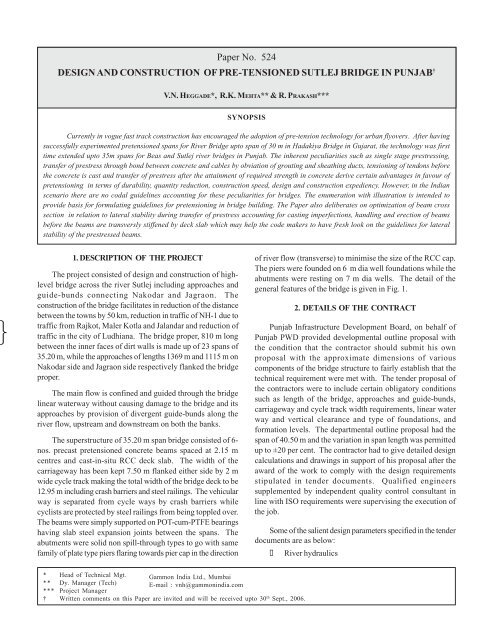
<strong>of</strong> river flow (transverse) to m<strong>in</strong>imise the size <strong>of</strong> the RCC cap.<br />
The piers were founded on 6 m dia well foundations while the<br />
abutments were rest<strong>in</strong>g on 7 m dia wells. The detail <strong>of</strong> the<br />
general features <strong>of</strong> the bridge is given <strong>in</strong> Fig. 1.<br />
2. DETAILS OF THE CONTRACT<br />
<strong>Punjab</strong> Infrastructure Development Board, on behalf <strong>of</strong><br />
<strong>Punjab</strong> PWD provided developmental outl<strong>in</strong>e proposal with<br />
the condition that the contractor should submit his own<br />
proposal with the approximate dimensions <strong>of</strong> various<br />
components <strong>of</strong> the bridge structure to fairly establish that the<br />
technical requirement were met with. The tender proposal <strong>of</strong><br />
the contractors were to <strong>in</strong>clude certa<strong>in</strong> obligatory conditions<br />
such as length <strong>of</strong> the bridge, approaches <strong>and</strong> guide-bunds,<br />
carriageway <strong>and</strong> cycle track width requirements, l<strong>in</strong>ear water<br />
way <strong>and</strong> vertical clearance <strong>and</strong> type <strong>of</strong> foundations, <strong>and</strong><br />
formation levels. The departmental outl<strong>in</strong>e proposal had the<br />
span <strong>of</strong> 40.50 m <strong>and</strong> the variation <strong>in</strong> span length was permitted<br />
up to ±20 per cent. The contractor had to give detailed design<br />
calculations <strong>and</strong> draw<strong>in</strong>gs <strong>in</strong> support <strong>of</strong> his proposal after the<br />
award <strong>of</strong> the work to comply with the design requirements<br />
stipulated <strong>in</strong> tender documents. Qualified eng<strong>in</strong>eers<br />
supplemented by <strong>in</strong>dependent quality control consultant <strong>in</strong><br />
l<strong>in</strong>e with ISO requirements were supervis<strong>in</strong>g the execution <strong>of</strong><br />
the job.<br />
Some <strong>of</strong> the salient design parameters specified <strong>in</strong> the tender<br />
documents are as below:<br />
River hydraulics
144<br />
• <strong>Design</strong> discharge : 18912 Cumecs<br />
• Maximum mean velocity : 4.87 m/sec<br />
• High flood level : RL 227.868<br />
• Depth <strong>of</strong> water at lowest : 3.0m<br />
water level<br />
• Scour level : RL 204.255<br />
Seismicity<br />
• Seismic zone : IV<br />
• Seismic coefficient : 0075G<br />
• Permissible <strong>in</strong>crease <strong>in</strong> SBC : 25 per cent<br />
• Permissible <strong>in</strong>crease <strong>in</strong> stress : As per IRC: 6<br />
Soil parameter<br />
• λ (dry) : 1.8 t/m 3<br />
• φ (angle <strong>of</strong> <strong>in</strong>ternal friction) : 30 0<br />
• δ (Friction between soil <strong>and</strong> face): 20 0<br />
• SBC for well foundation : 75 t/m 2 gross at<br />
found<strong>in</strong>g level.<br />
Material<br />
• For condition <strong>of</strong> exposure : Moderate<br />
• Concrete grades<br />
⇒For pretensioned beams : M40<br />
⇒For well foundation : M30<br />
⇒Re<strong>in</strong>forcements : HYSD bars<br />
conform<strong>in</strong>g to<br />
IS:1786<br />
HEGGADE, MEHTA & PRAKASH ON<br />
Fig. 1. General arrangement <strong>of</strong> <strong>Sutlej</strong> bridge<br />
Load<strong>in</strong>g<br />
• Live load :IRC 70R s<strong>in</strong>gle lane<br />
or Class-A 2 lanes<br />
• Footpath live load : As per IRC: 6<br />
• Cycle track load<strong>in</strong>g : As per IRC: 6<br />
Miscellaneous<br />
• Type <strong>of</strong> bear<strong>in</strong>gs : POT <strong>and</strong> POT cum<br />
PTFE<br />
• Wear<strong>in</strong>g coat : 25 mm thick mastic<br />
asphalt over 40 mm<br />
thick bitum<strong>in</strong>ous<br />
concrete<br />
• Cycle track <strong>and</strong> parapet : As per<br />
departmental<br />
draw<strong>in</strong>g<br />
• S<strong>of</strong>tware package : STAAD III -<br />
Release 22.0<br />
3. CONCEPTUALISATION<br />
In many <strong>of</strong> the river bridges <strong>in</strong> <strong>Punjab</strong> upto 45 m spans, the<br />
slab girder system with cast <strong>in</strong>situ post-tensioned beams are<br />
successfully adopted. Beyond 45 m, upto even 65 m cast <strong>in</strong>situ<br />
box girders are adopted. However, recently <strong>in</strong> vogue fast track
construction conceptualisation facilitates expeditious<br />
construction. The conventional cast <strong>in</strong>situ construction <strong>and</strong><br />
its expediencies like stag<strong>in</strong>g/trestle support for superstructure<br />
<strong>in</strong> the riverbed is not only time-consum<strong>in</strong>g, also susceptible to<br />
flood damages, consequently reduc<strong>in</strong>g productive work<strong>in</strong>g<br />
period <strong>in</strong> a season.<br />
In the recent years, the flyovers <strong>in</strong> urban areas especially<br />
<strong>in</strong> metropolitan cities are realised by precast construction. The<br />
various options <strong>in</strong> segmental <strong>and</strong> non-segmental technology<br />
is exploited <strong>in</strong> precast construction us<strong>in</strong>g post-tension<strong>in</strong>g or<br />
pre-tension<strong>in</strong>g.<br />
In case <strong>of</strong> <strong>Sutlej</strong> <strong>Bridge</strong>, among the various options<br />
available, f<strong>in</strong>ally the competition was between post-tensioned<br />
versus pre-tensioned beams. In this particular context, pretensioned<br />
beams had certa<strong>in</strong> advantages <strong>and</strong> also peculiarities<br />
vis-à-vis its counterpart.<br />
The <strong>in</strong>herent peculiarities such as s<strong>in</strong>gle-stage<br />
prestress<strong>in</strong>g, transfer <strong>of</strong> prestress through bond between<br />
concrete <strong>and</strong> cables by obviation <strong>of</strong> grout<strong>in</strong>g, sheath<strong>in</strong>g ducts,<br />
tension<strong>in</strong>g <strong>of</strong> tendons before the concrete is cast <strong>and</strong> transfer<br />
<strong>of</strong> prestress after the atta<strong>in</strong>ment <strong>of</strong> required strength <strong>in</strong> concrete,<br />
warrants specially designed cast<strong>in</strong>g bed which should be<br />
capable <strong>of</strong> impart<strong>in</strong>g required quantum <strong>of</strong> prestress<strong>in</strong>g force.<br />
These peculiarities derive certa<strong>in</strong> advantages <strong>in</strong> favour <strong>of</strong><br />
pretensioned beams <strong>in</strong> terms <strong>of</strong> durability, quantity reduction,<br />
construction speed, design <strong>and</strong> construction expediency. As<br />
the pretensioned girders are manufactured <strong>in</strong> factory like<br />
environment where the bond<strong>in</strong>g between concrete <strong>and</strong> tendons<br />
is direct due to the absence <strong>of</strong> grout<strong>in</strong>g <strong>in</strong>side the sheath<strong>in</strong>g<br />
duct, the better durability <strong>and</strong> corrosion resistance is achieved.<br />
The absence <strong>of</strong> the cables <strong>in</strong> the web <strong>and</strong> the elim<strong>in</strong>ation <strong>of</strong> end<br />
blocks <strong>and</strong> blisters to house the anchorages, allows the section<br />
optimisation from strength criteria alone. This helps <strong>in</strong> reduc<strong>in</strong>g<br />
concrete quantities render<strong>in</strong>g <strong>in</strong> lighter beams, facilitat<strong>in</strong>g <strong>in</strong><br />
attenuation <strong>in</strong> cost <strong>of</strong> h<strong>and</strong>l<strong>in</strong>g, transportation <strong>and</strong> erection.<br />
The value eng<strong>in</strong>eer<strong>in</strong>g carried out dur<strong>in</strong>g<br />
conceptualisation stage for <strong>Sutlej</strong> <strong>Bridge</strong> revealed that for the<br />
same span <strong>of</strong> 35.40 m <strong>and</strong> number <strong>of</strong> beams <strong>of</strong> six on the cross<br />
section (Fig. 2), the quantities for pre-tensioned girders are<br />
substantially lesser than post-tensioned beams.<br />
Fig. 2. <strong>Pre</strong>-tension<strong>in</strong>g vis-a-vis post-tension<strong>in</strong>g VE for <strong>Sutlej</strong><br />
bridge<br />
DESIGN AND CONSTRUCTION OF PRE-TENSIONED SUTLEJ BRIDGE IN PUNJAB<br />
145<br />
From the design angle, pre-tension<strong>in</strong>g uses the prestress<br />
efficiently on smaller sections with higher eccentricities,<br />
reduces the immediate losses like friction, wobble <strong>and</strong> slip,<br />
reduces <strong>in</strong>itial mass on substructure <strong>and</strong> foundation due to<br />
seismic <strong>and</strong> reduces steel congestion <strong>in</strong> end blocks <strong>and</strong><br />
anchorage zones. <strong>Construction</strong>-wise, the activities associated<br />
with post-tension<strong>in</strong>g such as thread<strong>in</strong>g <strong>of</strong> cable <strong>in</strong>side the<br />
sheath<strong>in</strong>g, grout<strong>in</strong>g operation <strong>and</strong> number <strong>of</strong> prestress<strong>in</strong>g<br />
operations is elim<strong>in</strong>ated.<br />
Though the pretensioned technology has been used<br />
extensively for flyovers <strong>and</strong> ROBs for the span range <strong>of</strong> 18 to<br />
22 m, for the first time for bridge across river Surajbari <strong>in</strong> Gujarat<br />
the technology was adopted with 26 m spans <strong>in</strong> India, which<br />
withstood the otherwise catastrophic earthquake <strong>in</strong> Gujarath<br />
on 26 th January 2001. Perhaps, it was but natural for <strong>Sutlej</strong> <strong>and</strong><br />
Beas <strong>Bridge</strong>s <strong>in</strong> <strong>Punjab</strong> to extend the span length up to 35 m as<br />
a part <strong>of</strong> evolutionary process, on the basis <strong>of</strong> experience ga<strong>in</strong>ed<br />
through the fast track flyovers <strong>and</strong> Surajbari <strong>Bridge</strong>.<br />
4. FOUNDATIONS<br />
Before the award <strong>of</strong> the job, as a part <strong>of</strong> tender documents<br />
a thorough soil <strong>in</strong>vestigation was carried out by the department<br />
to arrive at soil characteristics, soil bear<strong>in</strong>g capacity <strong>and</strong><br />
found<strong>in</strong>g levels along the bridge alignment (Fig. 3). Overall<br />
seven numbers <strong>of</strong> boreholes were drilled for depths up to 40 m<br />
<strong>and</strong> st<strong>and</strong>ard penetration tests were performed as per IS:2131<br />
to arrive at ‘N’ values. Silt factors were calculated on the basis<br />
<strong>of</strong> particle size distribution follow<strong>in</strong>g the pr<strong>in</strong>ciples <strong>of</strong> Lacey’s<br />
silt factor. On the basis <strong>of</strong> soil <strong>in</strong>vestigation, the subsoil strata<br />
were divided <strong>in</strong>to 3 dist<strong>in</strong>ct zones.<br />
Around 12 m below the ground level along the alignment a<br />
silty clay strata <strong>of</strong> average b<strong>and</strong> depth <strong>of</strong> around 12 m,<br />
designated as Zone-2 was s<strong>and</strong>wiched between s<strong>and</strong>y strata<br />
designated as Zone-1 <strong>and</strong> Zone-3. Average value <strong>of</strong> s<strong>and</strong>y<br />
strata was around 34 0 while clayey strata had undra<strong>in</strong>ed shear<br />
strength <strong>of</strong> around 1.50 kg/cm 2 (Cu). On the basis <strong>of</strong> 75 mm<br />
maximum settlement criteria, the bear<strong>in</strong>g pressure at found<strong>in</strong>g<br />
level <strong>in</strong> s<strong>and</strong>y strata after pass<strong>in</strong>g through the clayey strata<br />
was specified as 75T/m 2 on conservative side. The silt factor<br />
for Zone-1 varied from 0.62 to 1.07 while for Zone-3 the same<br />
was rang<strong>in</strong>g between 0.35 to 1.01. The design scour depths<br />
near the piers <strong>and</strong> abutments were evaluated on the basis <strong>of</strong><br />
maximum discharge, river regime <strong>and</strong> velocity <strong>of</strong> the river.<br />
In all 22 numbers <strong>of</strong> piers were supported on 32 m deep<br />
<strong>and</strong> 6 m dia well foundations (Fig. 4), consist<strong>in</strong>g <strong>of</strong> 2.1 m deep<br />
kerb, 1.5 m deep well cap. The ste<strong>in</strong><strong>in</strong>g thickness <strong>of</strong> 1.05 m is<br />
tapered to 0.75 m at scour depth <strong>of</strong> around 18 m, below the top<br />
<strong>of</strong> the well cap.<br />
The thickness <strong>of</strong> the ste<strong>in</strong><strong>in</strong>g was decided by us<strong>in</strong>g the<br />
relationship given <strong>in</strong> IRC:78 to facilitate smooth s<strong>in</strong>k<strong>in</strong>g by<br />
gravity without excessive Kent ledge <strong>and</strong> damage to ste<strong>in</strong><strong>in</strong>g
146<br />
HEGGADE, MEHTA & PRAKASH ON<br />
Fig. 3. Bore hole details along bridge alignment<br />
Fig. 4. Typical well foundation for <strong>Sutlej</strong>
due to differential earth pressure, s<strong>and</strong> blow <strong>and</strong> sudden drop,<br />
etc. it was ensured that the stresses at different levels <strong>of</strong> ste<strong>in</strong><strong>in</strong>g<br />
dur<strong>in</strong>g service conditions <strong>and</strong> construction stage were with<strong>in</strong><br />
permissible limits. As the well foundations were to be plugged<br />
on soil, the grip for side earth resistance below the scour level<br />
was ensured to be <strong>of</strong> the maximum depth <strong>of</strong> scour below the<br />
design scour. As normally, well cannot be sunk to the precise<br />
verticality, the design catered for the cumulative moment effect<br />
<strong>of</strong> 1 <strong>in</strong> 80 tilts <strong>and</strong> 150 mm shift apart from account<strong>in</strong>g for other<br />
severe load comb<strong>in</strong>ation. The side earth resistance was<br />
calculated by Bombay Committee Method with the passive<br />
resistance factor <strong>of</strong> safeties <strong>of</strong> 2.0 <strong>and</strong> 1.6 for normal <strong>and</strong> seismic<br />
conditions respectively. The well cap was designed <strong>and</strong> detailed<br />
as uniformly thick plate for the external reactions <strong>and</strong> reaction<br />
components at the bottom <strong>of</strong> the pier with boundary condition<br />
as partially fixed at supports on well ste<strong>in</strong><strong>in</strong>g all around.<br />
The river bed level varied between RL 222 m to 225.50 m<br />
hav<strong>in</strong>g deep channel between the pies P3 <strong>and</strong> P10 with the low<br />
water level be<strong>in</strong>g at RL 223.723 m. Up to the deep channel i.e.<br />
P10, the service road was made up to A/R <strong>and</strong> wells up to P10<br />
were started simultaneously. After the monsoon was over, on<br />
recession <strong>of</strong> floods, the service road was made on A/L side <strong>and</strong><br />
with the help <strong>of</strong> the site made temporary bridge between P8 <strong>and</strong><br />
P10; the wells were tackled <strong>in</strong> the channel.<br />
Initially, the well s<strong>in</strong>k<strong>in</strong>g was planned with four cranes.<br />
However, the s<strong>and</strong>wiched clayey strata necessitated overall<br />
eight cranes, as the s<strong>in</strong>k<strong>in</strong>g through the same was consum<strong>in</strong>g<br />
almost 7 to 15 days per metre depth.<br />
Most <strong>of</strong> the well foundations were constructed<br />
conventionally on l<strong>and</strong>, barr<strong>in</strong>g a couple <strong>in</strong> deep channels,<br />
which warranted s<strong>and</strong> isl<strong>and</strong>s.<br />
In the conventional construction (Photo 1.), the cutt<strong>in</strong>g<br />
edge fabricated <strong>of</strong> mild steel was laid on the ground level <strong>and</strong><br />
curb with required re<strong>in</strong>forcements was concreted. The material<br />
<strong>in</strong>side was gradually scooped out with grabs to facilitate s<strong>in</strong>k<strong>in</strong>g<br />
under its own weight. As the s<strong>in</strong>k<strong>in</strong>g proceeded, the ste<strong>in</strong><strong>in</strong>g<br />
was built up <strong>in</strong> lifts, normally <strong>of</strong> around 2.5 m to further the<br />
s<strong>in</strong>k<strong>in</strong>g due to <strong>in</strong>crease <strong>in</strong> weight.<br />
Photo 1. Curb re<strong>in</strong>forcements & cutt<strong>in</strong>g edge<br />
DESIGN AND CONSTRUCTION OF PRE-TENSIONED SUTLEJ BRIDGE IN PUNJAB<br />
147<br />
S<strong>in</strong>ce the bed pr<strong>of</strong>ile was hav<strong>in</strong>g large variations, almost<br />
all wells were required to be sunk up to 5 m below the ground<br />
level (Photo 2.) <strong>and</strong> 3.0 m below the water level. The circular<br />
c<strong>of</strong>ferdam except a small flare to accommodate piers was cast<br />
up to water level.<br />
Photo 2. C<strong>of</strong>ferdam with flare to accomodate pier<br />
Had the well cap level been fixed at ground level or LWL,<br />
the job could have been completed three to four months earlier<br />
<strong>and</strong> substantial additional expenditure as a consequence <strong>of</strong><br />
tak<strong>in</strong>g well cap below ground level could have been saved.<br />
As the c<strong>of</strong>ferdam was quite th<strong>in</strong> compared to ste<strong>in</strong><strong>in</strong>g, the<br />
non-availability <strong>of</strong> required weight hampered the s<strong>in</strong>k<strong>in</strong>g. This<br />
called for the creation <strong>of</strong> the sump below the found<strong>in</strong>g level to<br />
facilitate gradual s<strong>in</strong>k<strong>in</strong>g. At P16 location, the sump required<br />
was 3 m to enable last 1.80 m s<strong>in</strong>k<strong>in</strong>g. In the process the well<br />
jumped <strong>and</strong> sunk by 3.70 m at one go render<strong>in</strong>g the ste<strong>in</strong><strong>in</strong>g top<br />
almost 8 m (Photo 3.) below bed level.<br />
Photo 3. <strong>Construction</strong> <strong>of</strong> well cap below GL<br />
To raise the ste<strong>in</strong><strong>in</strong>g to the required level, the extensive<br />
shor<strong>in</strong>g, cont<strong>in</strong>uous dewater<strong>in</strong>g, protection with wire crated<br />
boulders, etc. had to be resorted to apart from stabilis<strong>in</strong>g the 6<br />
m deep false walls by adequate structural brac<strong>in</strong>gs.<br />
To circumvent the creation <strong>of</strong> sump to s<strong>in</strong>k last 1.2 m depth<br />
at P3 location, the other measures such as air jett<strong>in</strong>g, water<br />
jett<strong>in</strong>g <strong>and</strong> Kent ledge on top <strong>of</strong> false wall were attempted.<br />
F<strong>in</strong>ally after 4 months, the comb<strong>in</strong>ed effect <strong>of</strong> 450 t Kent ledge,<br />
5 m excavations outside the well <strong>and</strong> dewater<strong>in</strong>g yielded the<br />
well to the required depth.
148<br />
Though the aggregate s<strong>in</strong>k<strong>in</strong>g <strong>of</strong> 854 m was accomplished<br />
<strong>in</strong> a short period <strong>of</strong> 620 days, the good eng<strong>in</strong>eer<strong>in</strong>g practice <strong>of</strong><br />
fix<strong>in</strong>g the well cap at LWL/bed level, would have reduced the<br />
s<strong>in</strong>k<strong>in</strong>g duration, efforts <strong>and</strong> its f<strong>in</strong>ancial ramification quite<br />
considerably.<br />
At the every alternative well location, after reach<strong>in</strong>g the<br />
found<strong>in</strong>g level, the soil <strong>in</strong>vestigation was carried out up to 9 m<br />
depths to deduce ‘C’ <strong>and</strong> φ values to confirm the soil bear<strong>in</strong>g<br />
capacities. Bottom plugg<strong>in</strong>g was carried out by shift<strong>in</strong>g the<br />
concrete from batch<strong>in</strong>g plants through buckets <strong>and</strong> plac<strong>in</strong>g<br />
by tremie pipes. After hav<strong>in</strong>g done the recuperation test for<br />
soundness <strong>of</strong> plug after 14 days, the s<strong>and</strong> fill<strong>in</strong>g <strong>and</strong><br />
<strong>in</strong>termediate plugs were expedited. With the help <strong>of</strong><br />
irrecoverable shutter<strong>in</strong>g supported on precast beams <strong>and</strong><br />
c<strong>of</strong>ferdam, each well cap was completed with<strong>in</strong> five to six days<br />
<strong>in</strong>clud<strong>in</strong>g re<strong>in</strong>forcement fix<strong>in</strong>g <strong>and</strong> concret<strong>in</strong>g.<br />
5. PIERS<br />
The RCC piers were <strong>of</strong> wall type flar<strong>in</strong>g from well cap to<br />
accommodate the pier cap, with the concrete characteristic<br />
strength <strong>of</strong> 35 N/mm 2 . Though the grade <strong>of</strong> the concrete is<br />
same as that <strong>of</strong> used for well cap, the mix had to be made little<br />
richer with higher workability <strong>in</strong> order to enable smooth<br />
placement <strong>of</strong> concrete for the th<strong>in</strong> sections. A system <strong>of</strong><br />
formwork consist<strong>in</strong>g <strong>of</strong> steel channels <strong>and</strong> shutter<strong>in</strong>g was used<br />
<strong>in</strong> piers, which was concreted <strong>in</strong> two stages (Photo 4).<br />
Photo 4. Shutter<strong>in</strong>g Arrangement for Pier<br />
The height <strong>of</strong> the first lift was 3.25 m <strong>and</strong> after concret<strong>in</strong>g<br />
the first lift, the balance second lift shutter<strong>in</strong>g was fixed<br />
immediately <strong>in</strong> 3 to 5 hours. The grout leakage through the<br />
jo<strong>in</strong>ts <strong>of</strong> shutter<strong>in</strong>g was totally avoided by judicious plann<strong>in</strong>g<br />
dur<strong>in</strong>g the fabrication <strong>of</strong> shutter<strong>in</strong>g such as overlapp<strong>in</strong>g <strong>of</strong><br />
plates, etc. The concret<strong>in</strong>g for each lift was carried out <strong>in</strong><br />
cont<strong>in</strong>uous operation without the cold jo<strong>in</strong>t. By virtue <strong>of</strong> large<br />
shutter<strong>in</strong>g <strong>and</strong> m<strong>in</strong>imum number <strong>of</strong> lifts <strong>in</strong> concret<strong>in</strong>g, the surface<br />
texture <strong>of</strong> the concrete pier has been <strong>of</strong> excellent quality.<br />
6. SUPERSTRUCTURE<br />
6.1 Choice <strong>of</strong> Cross Section<br />
Due to the obvious advantages enumerated <strong>in</strong><br />
Conceptualisation Para, the an isotropic deck was considered<br />
HEGGADE, MEHTA & PRAKASH ON<br />
to be made up <strong>of</strong> 35.40 m long precast pretensioned beams,<br />
transversely held by 200 mm thick RCC deck slab. Though the<br />
design-wise <strong>and</strong> from aesthetical considerations, the<br />
<strong>in</strong>termediate diaphragms could have been avoided, the same<br />
has been provided to satisfy contractual requirement which<br />
are <strong>in</strong> fact structurally redundant.<br />
As there are no design criteria laid down <strong>in</strong> IRC st<strong>and</strong>ards<br />
for pretension<strong>in</strong>g, <strong>in</strong>variably IRC:18 meant for post-tensioned<br />
construction is adopted <strong>and</strong> <strong>in</strong>sisted upon, for pretension<br />
construction also. The present post-tensioned Code IRC:18<br />
prescribes work<strong>in</strong>g stress method <strong>of</strong> design <strong>and</strong> permissible<br />
stresses seem to be on highly conservative side. The<br />
comparable AASHTO-94, the st<strong>and</strong>ard that is also based on<br />
allowable stress method (ASD) design, allows at least 33 per<br />
cent higher flexural stresses dur<strong>in</strong>g transfer <strong>and</strong> 25 per cent<br />
higher flexural stresses dur<strong>in</strong>g service condition. To worsen<br />
the matter further, the ‘IRC’ stipulates 20 per cent additional<br />
time dependent losses, 3 times 1000 h relaxation losses, m<strong>in</strong>imum<br />
80 per cent <strong>of</strong> characteristic strength at full transfer <strong>of</strong> prestress,<br />
those perhaps are rationalised for post-tensioned construction<br />
on the basis <strong>of</strong> past experience, where prestress transfer is<br />
feasible <strong>in</strong> stages.<br />
Universally, though generally there are no separate codes<br />
for post-tension<strong>in</strong>g <strong>and</strong> pre-tension<strong>in</strong>g, the prestress<strong>in</strong>g code<br />
itself give separate design parameters such as time dependent<br />
loss parameters, permissible stresses <strong>and</strong> transmission length<br />
for pre-tension<strong>in</strong>g, etc. In view <strong>of</strong> this the author had suggested<br />
to IRC Code Mak<strong>in</strong>g Committee to make IRC: 18 a common<br />
code for prestressed concrete road bridges common for both<br />
pretensioned <strong>and</strong> post tensioned concrete with the separate<br />
design parameters wherever relevant <strong>and</strong> applicable, which is<br />
yet to be taken <strong>in</strong>to cognisance.<br />
Selection <strong>of</strong> the beam cross section for long span<br />
pretensioned girders warrants experience <strong>in</strong> field supervision,<br />
apart from theoretical aspects <strong>of</strong> prestressed concrete. It is<br />
expected that the optimum concrete section that is materially<br />
<strong>in</strong>fluenced by prestress<strong>in</strong>g force <strong>and</strong> load<strong>in</strong>g, is light for<br />
h<strong>and</strong>l<strong>in</strong>g <strong>and</strong> transportation, prestress<strong>in</strong>g operation <strong>and</strong><br />
concret<strong>in</strong>g friendly. The sizes <strong>of</strong> bottom <strong>and</strong> top flanges, the<br />
depth <strong>and</strong> width <strong>of</strong> web are required to be optimised on the<br />
basis <strong>of</strong> above constructability issues.<br />
The pressure l<strong>in</strong>e (resultant <strong>of</strong> stresses) <strong>in</strong> the prestressed<br />
concrete flexural member shifts its location with<strong>in</strong> the section<br />
upon the application <strong>of</strong> external loads. In simply supported<br />
beams at the midspan for service condition, the stress at the<br />
bottom-fibre is zero, i.e. no tension allowed as per codal<br />
provision. At the midspan pressure l<strong>in</strong>e is above the CG <strong>of</strong> the<br />
section, warrant<strong>in</strong>g the CG <strong>of</strong> the prestress<strong>in</strong>g force at a<br />
distance equivalent to moment divided by prestress<strong>in</strong>g force.<br />
Thus to cater for the compressive force by virtue <strong>of</strong> pressure<br />
l<strong>in</strong>e above the CG <strong>of</strong> section at the midspan, the top flange<br />
requirement is high, whereas nearly zero-stressed bottom fibre
does not require flange, apart from accommodat<strong>in</strong>g cables.<br />
Towards the supports as the moments are gradually reduced to<br />
zero, the CG <strong>of</strong> the prestress<strong>in</strong>g force can be judiciously located<br />
to be concentric to avoid any requirement <strong>of</strong> flanges.<br />
However, at the <strong>in</strong>terven<strong>in</strong>g stage before the application <strong>of</strong><br />
imposed loads <strong>in</strong>clud<strong>in</strong>g live load, the section has to store large<br />
prestress<strong>in</strong>g force at bottom fibre, which would be neutralised<br />
on application <strong>of</strong> external <strong>in</strong>termittent loads latter, br<strong>in</strong>g<strong>in</strong>g the<br />
bottom fibre stress to zero. The above calls for widen<strong>in</strong>g <strong>of</strong> the<br />
bottom flange <strong>and</strong> <strong>in</strong> fact decides the width. Thus an ‘I’ section<br />
where the pressure l<strong>in</strong>e can move larger distance without the<br />
tensile stresses is chosen for pretensioned girders. While the<br />
span to depth ratio ranges between 16 to 22, the web thickness<br />
<strong>of</strong> 150 mm is considered to be adequate for normal ‘I’ shaped<br />
beam for honeycomb-free concret<strong>in</strong>g.<br />
However, <strong>in</strong> case <strong>of</strong> <strong>Sutlej</strong> <strong>Bridge</strong> as the vertical clearance<br />
was not a constra<strong>in</strong>t, the lavish span to depth ratio <strong>of</strong> 14 was<br />
adopted to reduce the prestress<strong>in</strong>g str<strong>and</strong>s with the web<br />
thickness <strong>of</strong> 200 mm as constra<strong>in</strong>ed by IRC:18, though the same<br />
was not required by design <strong>and</strong> constructability angles.<br />
The decision on the width <strong>of</strong> the top flange is very crucial<br />
as the extremely narrow top flanges may buckle the precast<br />
beams dur<strong>in</strong>g side shift<strong>in</strong>g, transportation <strong>and</strong> h<strong>and</strong>l<strong>in</strong>g. The<br />
Indian Codes categorise the beams as slender beams when the<br />
span to top flange width ratio exceeds 60 or depth to flange<br />
width ratio exceeds 4 <strong>and</strong> specifies reduction <strong>in</strong> permissible<br />
stresses <strong>and</strong> adequate temporary restra<strong>in</strong>ts dur<strong>in</strong>g h<strong>and</strong>l<strong>in</strong>g<br />
<strong>and</strong> erection from lateral stability considerations. Normally,<br />
for the simply supported beams, the span to depth ratio <strong>of</strong> 15<br />
is considered to be optimum, <strong>and</strong> when the same is related to<br />
depth to width ratio <strong>of</strong> 4, the span to width ratio works out to<br />
be 60. In <strong>Sutlej</strong> <strong>and</strong> Beas bridges, 35 m long beams with 2.5 m<br />
depth was provided with 0.70 m top flange to keep the weight<br />
<strong>of</strong> the girder to m<strong>in</strong>imum with span to flange width ratio <strong>of</strong> 50<br />
<strong>and</strong> depth to width ratio <strong>of</strong> 3.57 satisfy<strong>in</strong>g both the<br />
considerations given <strong>in</strong> Indian Codes for slenderness. The<br />
stretch<strong>in</strong>g the slenderness to codal limits to keep the weight<br />
m<strong>in</strong>imum, was considered to be very bold especially after the<br />
classical beam collapses <strong>of</strong> Roop Narayan <strong>Bridge</strong> on National<br />
Highway No.6, where the span to width ratio 50 followed the<br />
depth to width ratio <strong>of</strong> 3 (safer than <strong>Sutlej</strong> <strong>Bridge</strong>). In his paper<br />
“A study <strong>of</strong> the failures dur<strong>in</strong>g launch<strong>in</strong>g <strong>of</strong> precast prestressed<br />
concrete beams <strong>of</strong> the Roop Narayan <strong>Bridge</strong> on National<br />
Highway No. 6”, while deliberat<strong>in</strong>g on Guyon’s contention that<br />
for the beams depths <strong>of</strong> 5 to 8 ft., the thickness <strong>of</strong> the flanges<br />
should never be less than 0.1 <strong>of</strong> the depth <strong>and</strong> width <strong>of</strong> the<br />
flanges should not be less than 0.40 <strong>of</strong> the depth for<br />
symmetrical I-beams, Mr. Seetharaman through his<br />
<strong>in</strong>vestigation concludes that the span to depth ratio should<br />
be 15 <strong>and</strong> depth to width ratio should be less than 3 for<br />
transverse rigidity <strong>of</strong> precast beams. Thus the chosen beam<br />
section for <strong>Sutlej</strong> called for thorough <strong>in</strong>vestigation <strong>and</strong><br />
justification vis-à-vis lateral stability dur<strong>in</strong>g transfer <strong>of</strong><br />
DESIGN AND CONSTRUCTION OF PRE-TENSIONED SUTLEJ BRIDGE IN PUNJAB<br />
149<br />
prestress, h<strong>and</strong>l<strong>in</strong>g <strong>and</strong> erection <strong>of</strong> the beams before the<br />
beams are transversely rigidised by deck slab.<br />
The lateral stability <strong>of</strong> <strong>Sutlej</strong> beams dur<strong>in</strong>g h<strong>and</strong>l<strong>in</strong>g <strong>and</strong><br />
erection was ensured by extensive <strong>in</strong>vestigations on the basis<br />
<strong>of</strong> special report “lateral stability <strong>of</strong> long prestressed concrete<br />
beams” by Robert F. Mait <strong>in</strong> PCI Journal Jan-Feb 1989.<br />
The improper lift<strong>in</strong>g hook placement <strong>and</strong> cast<strong>in</strong>g<br />
imperfection cause the beam to be tilted at an <strong>in</strong>itial angle θ1 near the lift<strong>in</strong>g hook location about the roll axis (Fig. 5).<br />
Normally the cast<strong>in</strong>g imperfections considered 1:1920 <strong>in</strong> <strong>Sutlej</strong><br />
gets manifested itself by way <strong>of</strong> curvature <strong>in</strong> plan <strong>of</strong><br />
prestressed beam after detension<strong>in</strong>g. Lift<strong>in</strong>g hook placement<br />
tolerance was allowed to be 6.35 mm dur<strong>in</strong>g cast<strong>in</strong>g. The<br />
above tilt<strong>in</strong>g <strong>of</strong> beam <strong>in</strong>duces the lateral deflection about<br />
weak axis <strong>of</strong> the beam. Because <strong>of</strong> the transfer <strong>of</strong> prestress,<br />
there is already tension at the top fibre <strong>of</strong> the beam for which<br />
the tensile stress caused about the weak axis by the<br />
component <strong>of</strong> the self weight due to tilt gets added which<br />
needs to be with<strong>in</strong> the permissible limits <strong>and</strong> <strong>in</strong> fact decides<br />
the maximum tilt (θ max) to which the beam can be subjected<br />
to. After the tilt<strong>in</strong>g is <strong>in</strong>itiated by the <strong>in</strong>itial angle θ near the<br />
1<br />
support locations, the beam achieves its equilibrium with a<br />
uniform lift angle θ (shown at midspan) with CG <strong>of</strong> the mass<br />
<strong>of</strong> the deflected beam right under the roll axis.<br />
In the figure as Z approaches Y , the beam starts rotat<strong>in</strong>g<br />
o r<br />
<strong>and</strong> becomes totally unstable even without the <strong>in</strong>itial<br />
imperfection <strong>and</strong> without improper location <strong>of</strong> lift<strong>in</strong>g hook.<br />
Thus the safety aga<strong>in</strong>st the lateral buckl<strong>in</strong>g is a measure <strong>of</strong><br />
Y vis-à-vis Zo <strong>and</strong> is called gross factor <strong>of</strong> safety (FOS = Y /<br />
r r<br />
Z ) for a perfect beam without imperfection.<br />
o<br />
If one has to account for imperfections caus<strong>in</strong>g the <strong>in</strong>itial<br />
angle q <strong>and</strong> limit<strong>in</strong>g the maximum lift to θ , the factor <strong>of</strong><br />
1 max<br />
safety reduces to .<br />
However, it is more logical to deduce the factor <strong>of</strong> safety<br />
aga<strong>in</strong>st lateral stability by divid<strong>in</strong>g maximum possible tilt θ max<br />
with that <strong>of</strong> equilibrium rotation θ at midspan.<br />
Mov<strong>in</strong>g the lift<strong>in</strong>g position <strong>in</strong>wards improves the factor<br />
<strong>of</strong> safety aga<strong>in</strong>st lateral stability by virtue <strong>of</strong> reduced<br />
deflections caused by rotations about the weak axis.<br />
However, it has to be ensured that the stresses are with<strong>in</strong><br />
the limits <strong>in</strong> overhang portions.<br />
Though the very slender cross sections from lateral<br />
stability considerations was chosen <strong>in</strong> <strong>Sutlej</strong> <strong>Bridge</strong>, the same<br />
could be successfully executed by adher<strong>in</strong>g to the specified<br />
cast<strong>in</strong>g imperfections, lift<strong>in</strong>g hook location tolerance, etc.<br />
dur<strong>in</strong>g execution. The details <strong>of</strong> the same are given <strong>in</strong> Fig. 5.<br />
Unlike <strong>in</strong> post-tension<strong>in</strong>g, <strong>in</strong> case <strong>of</strong> pre-tension<strong>in</strong>g as the<br />
str<strong>and</strong>s are bonded dur<strong>in</strong>g the transfer <strong>of</strong> prestress, the
150<br />
Fig. 5. Laterial stability <strong>of</strong> long prestressed concrete beams with factor <strong>of</strong> safeties<br />
beams cannot buckle which was also taken <strong>in</strong>to cognisance<br />
dur<strong>in</strong>g lateral stability <strong>in</strong>vestigations.<br />
The lateral stability guidel<strong>in</strong>es for precast beams given <strong>in</strong><br />
Indian Codes for prestressed concrete members are similar to<br />
that <strong>of</strong> for RCC <strong>and</strong> steel beams <strong>in</strong> terms <strong>of</strong> span to depth ratio<br />
<strong>and</strong> depth to top flange width ratio. However, <strong>in</strong> the case <strong>of</strong><br />
prestressed beams, the aspect <strong>of</strong> prestress<strong>in</strong>g is a new variable<br />
<strong>and</strong> as such the same guidel<strong>in</strong>es may not be applicable for<br />
prestressed beams. In view <strong>of</strong> this the factor <strong>of</strong> safeties<br />
enumerated above may be <strong>in</strong>cluded for ensur<strong>in</strong>g the lateral<br />
stability <strong>of</strong> beams dur<strong>in</strong>g shift<strong>in</strong>g, transportation <strong>and</strong> erection<br />
<strong>of</strong> prestressed, precast beams <strong>in</strong> the prestressed concrete<br />
codes.<br />
6.2. <strong>Design</strong> <strong>of</strong> Superstructure<br />
The superstructure consists <strong>of</strong> six numbers <strong>of</strong> precast<br />
pretensioned girders spaced at 2.15 m centre to centre with 250<br />
mm thick end diaphragms to support 200 mm thick cast-<strong>in</strong>-site<br />
RCC deck cantilever<strong>in</strong>g by 1.10 m from the centre l<strong>in</strong>e <strong>of</strong> external<br />
girders on either side. The pretensioned girders <strong>in</strong> the cast<strong>in</strong>g<br />
yard were specified to be prestressed after 24 hours when the<br />
strength <strong>of</strong> the concrete was 31 MPa, while the concrete grade<br />
for the beams were M 40.<br />
The precast girders were transported to site <strong>and</strong> placed on<br />
bear<strong>in</strong>gs followed by cast<strong>in</strong>g <strong>of</strong> the end diaphragm. The RCC<br />
deck slab was cast on formwork supported on girders <strong>and</strong> the<br />
HEGGADE, MEHTA & PRAKASH ON<br />
same was removed after the sufficient atta<strong>in</strong>ment <strong>of</strong> strength <strong>in</strong><br />
the deck. Thereafter, for the further loads such as weight <strong>of</strong><br />
crash barrier, wear<strong>in</strong>g coat, rail<strong>in</strong>gs <strong>and</strong> live load, etc. the<br />
structure was assured to be a composite section. The effect <strong>of</strong><br />
differential shr<strong>in</strong>kage <strong>and</strong> temperature variation were also<br />
considered <strong>in</strong> the design.<br />
For f<strong>in</strong>d<strong>in</strong>g all the longitud<strong>in</strong>al beam reaction components,<br />
the grillage analysis (Fig. 6) was used for superimposed dead<br />
loads <strong>and</strong> live loads, the structure was idealised as a grid <strong>of</strong><br />
longitud<strong>in</strong>al <strong>and</strong> transverse members. The composite girders<br />
consist<strong>in</strong>g <strong>of</strong> precast beam <strong>and</strong> deck slab was descretised to<br />
be placed along the axis <strong>of</strong> the girder while deck slab <strong>and</strong> deck<br />
slab with diaphragm was placed as transverse grillage members<br />
along the l<strong>in</strong>e <strong>of</strong> each <strong>of</strong> end diaphragm <strong>in</strong> the structure. The<br />
slab acts to transmit applied loads to beams by spann<strong>in</strong>g<br />
transversely between them, apart from provid<strong>in</strong>g means for<br />
load shar<strong>in</strong>g between longitud<strong>in</strong>al beams. Therefore transverse<br />
members hav<strong>in</strong>g slab properties were provided to reflect the<br />
load shar<strong>in</strong>g characteristics <strong>of</strong> the deck. For the application <strong>of</strong><br />
the loads due to rail<strong>in</strong>g, the dummy longitud<strong>in</strong>al members with<br />
negligible section properties were provided at the edges <strong>and</strong><br />
transverse grillage members were cont<strong>in</strong>ued to connect them.<br />
The flar<strong>in</strong>g properties <strong>of</strong> precast beams at the end for the<br />
distance <strong>of</strong> 2.65 m from 200 mm to 300 mm thick has been<br />
accounted for <strong>in</strong> the descretisation.<br />
The grillage analysis results especially for superimposed
Fig. 6. Grillage idealisation for deck slab with girders<br />
dead loads <strong>and</strong> live loads were compared with Classical Little<br />
<strong>and</strong> Morrice method for verification, which were found to be <strong>in</strong><br />
agreement to a large extent as illustrated <strong>in</strong> Table 1.<br />
TABLE 1. GRILLAGE ANALYSIS VIA-A-VIS LITTLE & MORRICE<br />
METHOD<br />
The stresses <strong>in</strong> bottom <strong>and</strong> top fibres <strong>of</strong> the beam before<br />
<strong>and</strong> after the composite action were ensured to be with<strong>in</strong> the<br />
permissible limits as specified <strong>in</strong> IRC:18 at various temporary<br />
<strong>and</strong> service stages as tabulated <strong>in</strong> Table 2.<br />
TABLE 2. SUMMARY OF STRESSES AT MID SPAN<br />
DESIGN AND CONSTRUCTION OF PRE-TENSIONED SUTLEJ BRIDGE IN PUNJAB<br />
In case <strong>of</strong> the pretensioned girders with straight tendons,<br />
151<br />
the prestress<strong>in</strong>g moments near the simply supported ends<br />
need to be reduced as the moments <strong>in</strong>duced by self weight<br />
<strong>and</strong> external loads gradually dim<strong>in</strong>ishes towards the supports<br />
from midspan. The same is achieved by prevent<strong>in</strong>g the portion<br />
<strong>of</strong> the tendons from bond<strong>in</strong>g, thereby prevent<strong>in</strong>g from<br />
stress<strong>in</strong>g the concrete at the ends. Normally, the bond<br />
prevention is achieved by provision <strong>of</strong> tight-fitt<strong>in</strong>g split plastic<br />
tube or heavy paper or cloth tape. However, for the accurate<br />
placement <strong>of</strong> tubes after the pre-tension<strong>in</strong>g a 20 mm dia ‘PVC’<br />
tubes were used <strong>in</strong> <strong>Sutlej</strong> <strong>Bridge</strong> as bond prevention media at<br />
the ends (Fig. 7).<br />
The length <strong>of</strong> bond prevention has to be deduced after<br />
cater<strong>in</strong>g for “transmission length” required to develop full<br />
tension <strong>in</strong> the tendons.<br />
When the pretension<strong>in</strong>g tendon is stressed, the diameter<br />
<strong>of</strong> the tendon is reduced due to poison’s effect <strong>and</strong> the orig<strong>in</strong>al<br />
diameter is rega<strong>in</strong>ed after the release <strong>of</strong> prestress. In fact this<br />
property is responsible for bond<strong>in</strong>g pretensioned wires to<br />
concrete. After the detension<strong>in</strong>g, the stress <strong>in</strong> the wire at the<br />
end is zero <strong>and</strong> maximum after certa<strong>in</strong> length, which is called<br />
“transmission length”. The Hoyer was the first German<br />
Eng<strong>in</strong>eer who developed the theory <strong>of</strong> “transmission length”<br />
due to the formation <strong>of</strong> wedge shape <strong>in</strong> prestress<strong>in</strong>g tendon<br />
where the stress gradually decreases from maximum to zero<br />
with the <strong>in</strong>crease <strong>in</strong> diameter <strong>of</strong> tendon, which is popularly<br />
referred as “Hoyer’s effect”.<br />
The transmission length depends upon number <strong>of</strong><br />
variables, the most important be<strong>in</strong>g the strength <strong>of</strong> the concrete<br />
at the time <strong>of</strong> transfer, the size <strong>of</strong> the tendon, friction between<br />
the tendon <strong>and</strong> concrete <strong>and</strong> <strong>in</strong>itial <strong>and</strong> effective stresses <strong>in</strong><br />
steel. As per the guidel<strong>in</strong>es <strong>of</strong> IS:1343, 30 times the diameter <strong>of</strong><br />
the tendon for str<strong>and</strong>s i.e. around 500 mm was considered as<br />
transmission length <strong>in</strong> the said bridge. It is <strong>in</strong>terest<strong>in</strong>g to note<br />
that the stress variation over transmission length be<strong>in</strong>g<br />
parabolic, 80 per cent <strong>of</strong> the maximum prestress is developed<br />
over half the transmission length, <strong>and</strong> as such half <strong>of</strong> the<br />
transmission length was projected beyond bear<strong>in</strong>g supports<br />
for simply supported girders.<br />
7. PRE-TENSIONING<br />
The bridge <strong>of</strong> 23 spans consisted <strong>of</strong> 138 nos, 35.2 m long,<br />
68 tonne weigh<strong>in</strong>g, prestressed beams with the depth <strong>of</strong> 2.50<br />
m. Each beam consisted <strong>of</strong> 34 nos. <strong>of</strong> str<strong>and</strong>s (tendons)<br />
conform<strong>in</strong>g to class-2 <strong>of</strong> IS:14268 with UTS <strong>of</strong> 1900 N/mm 2 .<br />
Each str<strong>and</strong> <strong>of</strong> 15.2 mm dia was made up <strong>of</strong> 7 wires with 6 wires<br />
surround<strong>in</strong>g the centre wire configuration result<strong>in</strong>g <strong>in</strong><br />
enhanced bond characteristics due to Hoyer’s effect, with net<br />
str<strong>and</strong> cross sectional area <strong>of</strong> 140 mm 2 .<br />
The key factors <strong>in</strong> the choice <strong>and</strong> capacity <strong>of</strong><br />
pretension<strong>in</strong>g bed was the availability <strong>of</strong> time for precast<strong>in</strong>g<br />
girders <strong>and</strong> the economical considerations. The cost benefit
152<br />
analysis for various capacities <strong>of</strong> long l<strong>in</strong>e pre tension<strong>in</strong>g bed<br />
was carried out as per the Table 3. S<strong>in</strong>ce the expenditure on<br />
three beams cast<strong>in</strong>g was found to be economically optimum,<br />
sav<strong>in</strong>g almost 15 months, the bed for cast<strong>in</strong>g three beams was<br />
chosen, mak<strong>in</strong>g perhaps the longest pretension<strong>in</strong>g bench <strong>in</strong><br />
the country with the length <strong>of</strong> 122.5 m, for stress<strong>in</strong>g 115 m long<br />
str<strong>and</strong>s (Fig. 8).<br />
TABLE. 3. COST BENEFIT ANALYSIS OF PRETENSIONING BENCH<br />
HEGGADE, MEHTA & PRAKASH ON<br />
Fig. 7. Debond<strong>in</strong>g arrangement for st<strong>and</strong>s at the ends<br />
The largest long l<strong>in</strong>e prestress<strong>in</strong>g bed had its own share <strong>of</strong><br />
problems. Each str<strong>and</strong> was to be stressed to 21 tonnes,<br />
warrant<strong>in</strong>g the capacity <strong>of</strong> the pretension<strong>in</strong>g bench to (2x34) =<br />
714 tonnes. It is essential to design the pretension<strong>in</strong>g bed to<br />
additional 20 per cent capacity as the prestress<strong>in</strong>g force on<br />
reaction abutment (Fig. 9) will <strong>in</strong>crease due to “long l<strong>in</strong>e bench<br />
effect” after cast<strong>in</strong>g <strong>of</strong> concrete, due to shr<strong>in</strong>kage <strong>and</strong><br />
temperature variation between the duration <strong>of</strong> cast<strong>in</strong>g <strong>of</strong><br />
concrete <strong>and</strong> detension<strong>in</strong>g. Prior to detension<strong>in</strong>g <strong>in</strong> the cast<strong>in</strong>g<br />
yard, the str<strong>and</strong>s can be stressed up to 0.80 UTS. Due to the<br />
shr<strong>in</strong>kage <strong>of</strong> concrete clubbed with reduction <strong>in</strong> temperature,<br />
shr<strong>in</strong>ks the concrete along with the str<strong>and</strong>s <strong>in</strong> the bonded length<br />
thereby elongat<strong>in</strong>g <strong>and</strong> <strong>in</strong>duc<strong>in</strong>g further stress <strong>in</strong> the unbonded<br />
length. If the <strong>in</strong>crease <strong>in</strong> stress <strong>in</strong> unbonded length before<br />
Fig. 8. <strong>Pre</strong> tension<strong>in</strong>g bench <strong>of</strong> 122.5 m, for stress<strong>in</strong>g 15 m long str<strong>and</strong>s
Fig. 9. Cross section <strong>of</strong> Bulkhead<br />
detension<strong>in</strong>g is beyond UTS, the str<strong>and</strong>s <strong>in</strong> some cases may<br />
even start snapp<strong>in</strong>g, as happened <strong>in</strong> <strong>Sutlej</strong> <strong>Bridge</strong>. The <strong>in</strong>crease<br />
<strong>in</strong> the stress <strong>of</strong> the unbonded tendon is directly proportionate<br />
to the ratio <strong>of</strong> the length <strong>of</strong> the embedded str<strong>and</strong>s to that <strong>of</strong><br />
total str<strong>and</strong> length. This is also affected by cur<strong>in</strong>g time <strong>and</strong> is<br />
more severe when the ambient temperature dur<strong>in</strong>g stripp<strong>in</strong>g is<br />
low.<br />
The key decisive factors <strong>in</strong> the choice <strong>of</strong> formwork for<br />
pretensioned girders were:<br />
(a) High resistance to damage due to rough h<strong>and</strong>l<strong>in</strong>g.<br />
(b) The precise dimension <strong>of</strong> the panels to fit together to<br />
form a large unit with ease.<br />
(c) Clean<strong>in</strong>g, sett<strong>in</strong>g, adjust<strong>in</strong>g <strong>and</strong> h<strong>and</strong>l<strong>in</strong>g ease.<br />
(d) The ability <strong>of</strong> erect<strong>in</strong>g one side <strong>in</strong>dependent <strong>of</strong> other.<br />
(e) The ability to withst<strong>and</strong> the form <strong>and</strong> other vibrations.<br />
(f) Rigid structural s<strong>of</strong>fit form to secure <strong>and</strong> hold the side<br />
form without movement dur<strong>in</strong>g concret<strong>in</strong>g.<br />
(g) The m<strong>in</strong>imum jo<strong>in</strong>ts, which can be tightly sealed to<br />
avoid leakage <strong>and</strong> bleed<strong>in</strong>g.<br />
The shutter<strong>in</strong>g panels <strong>of</strong> 3 m length were erected us<strong>in</strong>g<br />
8-ton capacity hydro crane, which was supported on ground<br />
anchors by turnbuckles. After erection <strong>of</strong> one face <strong>of</strong><br />
shutter<strong>in</strong>g the alignments to the precision could be carried out<br />
by adjustments <strong>of</strong> turnbuckles. After the erection <strong>of</strong> one face<br />
<strong>of</strong> shutter<strong>in</strong>g the alignment to the precision could be carried<br />
out by adjustment <strong>of</strong> turnbuckles. After the erection <strong>of</strong> one<br />
DESIGN AND CONSTRUCTION OF PRE-TENSIONED SUTLEJ BRIDGE IN PUNJAB<br />
153<br />
shutter<strong>in</strong>g face, the re<strong>in</strong>forcement cages fabricated <strong>in</strong> three<br />
pieces <strong>of</strong> 11 m each were shifted to cast<strong>in</strong>g bed by hydro<br />
crane. The cages were suitably stiffened by diagonal bars<br />
dur<strong>in</strong>g transportation, which were removed once placed <strong>in</strong><br />
position <strong>in</strong> cast<strong>in</strong>g bed.<br />
HT str<strong>and</strong>s were cut to 115 m length <strong>and</strong> stacked over<br />
raised platform along the l<strong>in</strong>e <strong>of</strong> cast<strong>in</strong>g bed. While open<strong>in</strong>g<br />
the coil, HT str<strong>and</strong>s were passed through water tank to<br />
remove protective coat<strong>in</strong>g. The cables were threaded manually<br />
<strong>in</strong>sert<strong>in</strong>g through 20 mm dia ‘PVC’ pipes <strong>of</strong> required length<br />
meant for debond<strong>in</strong>g. After fix<strong>in</strong>g up the anchorages, the<br />
cables were prestressed from stress<strong>in</strong>g end <strong>in</strong> predeterm<strong>in</strong>ed<br />
sequence. The debond<strong>in</strong>g pipes were positioned <strong>and</strong> sealed<br />
with epoxy <strong>and</strong> tapes as per the draw<strong>in</strong>g after the stressed<br />
cables were anchored. The other face <strong>of</strong> the shutter<strong>in</strong>g was<br />
then lifted up <strong>and</strong> connected to already erect face by 16 mm<br />
through bolts. The gaps were filled with foams for prevent<strong>in</strong>g<br />
leakage <strong>and</strong> one end <strong>of</strong> the shutter<strong>in</strong>g was provided with 50<br />
mm wooden pack<strong>in</strong>g <strong>and</strong> thermo coal to facilitate easy removal<br />
<strong>of</strong> shutter<strong>in</strong>g after concret<strong>in</strong>g.<br />
The concrete produced by batch<strong>in</strong>g plant <strong>of</strong> capacity 30<br />
m 3 /hr as per the design mix (Table 4.) transported through a<br />
lead <strong>of</strong> 100 m by tractor trolley. As the concrete was to be<br />
placed at height <strong>of</strong> 3.5 m from supply level a mechanical mode<br />
was devised for placement. The device consisted <strong>of</strong> an<br />
automatic conveyor designed <strong>and</strong> fabricated (Fig. 10) at site<br />
<strong>in</strong> such way that it could move on a track l<strong>in</strong>e parallel to<br />
pretension<strong>in</strong>g bed, receive concrete from trolleys up to 0.50<br />
m 3 at a time, carry the concrete through conveyor for 3.50 m<br />
height <strong>and</strong> deliver to tremie for placement through funnel. The<br />
device could be electrically operated by operator seated on<br />
it, <strong>and</strong> reduced the concret<strong>in</strong>g cycle to 2 hours from manual<br />
concret<strong>in</strong>g cycle <strong>of</strong> 5 hours. The concrete compaction was<br />
achieved by poker <strong>and</strong> shutter vibrators.<br />
TABLE 4. DESIGN MIX DETAILS<br />
The transfer <strong>of</strong> prestress was <strong>in</strong>duced by cutt<strong>in</strong>g str<strong>and</strong><br />
by acetylene torch <strong>in</strong> a pre-decided sequence after concrete<br />
achieved the strength <strong>of</strong> 31 MPa. The best cycle time achieved<br />
<strong>in</strong> the beam cast<strong>in</strong>g was 66 hours though on a average time
154<br />
Fig. 10. Mechanical device for concrete placement<br />
cycle was 72 hours with the <strong>in</strong>dividual activity break-up as<br />
shown <strong>in</strong> Table 5.<br />
TABLE 5. CYCLE TIME FOR BEAM CASTING<br />
Despite the unforeseen impediments like non-availability<br />
<strong>of</strong> stack<strong>in</strong>g facilities, repairs <strong>of</strong> shutter<strong>in</strong>g panels, ma<strong>in</strong>tenance<br />
<strong>of</strong> bed alignment, <strong>and</strong> ra<strong>in</strong>, etc. the cast<strong>in</strong>g <strong>of</strong> 138 nos. <strong>of</strong><br />
beams were completed <strong>in</strong> 320 days.<br />
The pretension<strong>in</strong>g can be done either by stress<strong>in</strong>g each<br />
tendon <strong>in</strong>dividually or all together at a time. As the stress<strong>in</strong>g<br />
<strong>in</strong>dividually called for monostr<strong>and</strong> jack <strong>of</strong> 25 T capacity with<br />
a stroke 1000 mm, the <strong>in</strong>dividual stress<strong>in</strong>g <strong>of</strong> str<strong>and</strong>s was<br />
resorted to.<br />
8. BEAM ERECTION<br />
The transportation <strong>and</strong> erection <strong>of</strong> beams were<br />
accomplished (Fig. 11) by 3 pairs <strong>of</strong> side shift<strong>in</strong>g trolleys, a<br />
pair <strong>of</strong> motorised longitud<strong>in</strong>al trolleys <strong>and</strong> a pair <strong>of</strong> 35-toon<br />
capacity bed gantries. The side shift<strong>in</strong>g trolleys were used<br />
to shift the beams from cast<strong>in</strong>g bed to stack<strong>in</strong>g yard <strong>and</strong> from<br />
there to longitud<strong>in</strong>ally motorised trolleys with the help <strong>of</strong><br />
jacks. The longitud<strong>in</strong>al trolleys be<strong>in</strong>g designed at lower levels,<br />
the beams brought by side shift<strong>in</strong>g trolleys were lowered to<br />
HEGGADE, MEHTA & PRAKASH ON<br />
longitud<strong>in</strong>al trolleys.<br />
To facilitate the movement <strong>of</strong> bed gantries <strong>and</strong><br />
longitud<strong>in</strong>al trolleys, the track l<strong>in</strong>e is laid on wooden sleepers<br />
at 0.70 m c/c as per railway specification over well-prepared<br />
compacted embankments. The motorised trolleys were moved<br />
up to the span where beam was to be erected. The gantries<br />
were used at the location to lift, side shift <strong>and</strong> lower<strong>in</strong>g <strong>of</strong><br />
beam on pedestal as depicted <strong>in</strong> the Fig. 12 & 13. The lift<strong>in</strong>g<br />
was done with the aid <strong>of</strong> 750 mm stroke hydraulic jacks <strong>and</strong> 16<br />
m long suspenders. The side shift<strong>in</strong>g was done us<strong>in</strong>g the crab<br />
assembly <strong>and</strong> w<strong>in</strong>ches set on top <strong>of</strong> gantries. Prior to the<br />
lift<strong>in</strong>g <strong>of</strong> the beams, the bear<strong>in</strong>gs were fixed at the s<strong>of</strong>fit <strong>of</strong><br />
beams with sleeves already embedded dur<strong>in</strong>g concret<strong>in</strong>g. The<br />
surface irregularities were dealt by application <strong>of</strong> 2 mm thick<br />
epoxy over the bear<strong>in</strong>gs. The lowered beams were rested at<br />
about 20 mm above the pedestal <strong>and</strong> the recess was grouted<br />
us<strong>in</strong>g non-shr<strong>in</strong>k cement grout. Till the time the recess was<br />
grouted <strong>and</strong> end diaphragms were cast, the beams were placed<br />
on wooden sleepers <strong>and</strong> held by temporary brac<strong>in</strong>gs.<br />
On an average 5 hours cycle was comfortably achieved<br />
as shown <strong>in</strong> the Table 6. with the progress <strong>of</strong> 3 beams per day<br />
on a regular basis.<br />
TABLE 6. CYCLE TIME FOR BEAM ERECTION<br />
In the water spans, between A/R to P8 <strong>and</strong> P10 to A/L, the<br />
bed gantries <strong>and</strong> longitud<strong>in</strong>al trolleys were moved on railway<br />
track over specially constructed embankments with the<br />
provision <strong>of</strong> hume pipes at suitable <strong>in</strong>tervals for pass<strong>in</strong>g the<br />
water from u/s to d/s. However, not to constrict the water <strong>in</strong> a<br />
too narrow passage, a temporary service bridge was made on<br />
both sides <strong>of</strong> the piers to move the bed gantries between P8<br />
<strong>and</strong> P10. This temporary bridge had s<strong>in</strong>gle-l<strong>in</strong>e <strong>of</strong> pil<strong>in</strong>g on d/<br />
s side to cater for the movement <strong>of</strong> one leg <strong>of</strong> the gantry where<br />
as on upstream side two l<strong>in</strong>es <strong>of</strong> piles were provided to move<br />
longitud<strong>in</strong>al trolleys <strong>and</strong> transport other materials.
Fig. 12. Show<strong>in</strong>g the Erection scheme <strong>of</strong> Beam<br />
Fig. 13. Erection, side shift<strong>in</strong>g & placement<br />
The s<strong>in</strong>gle l<strong>in</strong>e <strong>of</strong> piles on downstream side was collapsed<br />
dur<strong>in</strong>g floods when the erection was <strong>in</strong> progress between P7 &<br />
A/L on Nakodar side. However, on Jagraon side the gantry<br />
was to be brought back to erect the beams on unf<strong>in</strong>ished span<br />
A/R-P22. Among the alternatives considered, provid<strong>in</strong>g a<br />
DESIGN AND CONSTRUCTION OF PRE-TENSIONED SUTLEJ BRIDGE IN PUNJAB<br />
Fig. 11. Cast<strong>in</strong>g Yard Layout for <strong>Sutlej</strong><br />
155<br />
trolley on top <strong>of</strong> the deck slab <strong>and</strong> support<strong>in</strong>g half <strong>of</strong> the gentry<br />
(Fig. 14) on it proved to be safe, economical <strong>and</strong> fastest solution.<br />
This method was adopted for shift<strong>in</strong>g both the gantries across<br />
P8 & P10 <strong>in</strong> seven days time without any risk <strong>and</strong> just tak<strong>in</strong>g<br />
care by dropp<strong>in</strong>g plumbs at four locations on both sides <strong>of</strong> the<br />
gantry to check the evenness <strong>of</strong> the movement.<br />
Fig. 14. Transportation <strong>of</strong> gantry on deck<br />
9. BEARINGS<br />
POT <strong>and</strong> POT-cum-PTFE bear<strong>in</strong>gs were used <strong>in</strong> the <strong>Sutlej</strong><br />
<strong>Bridge</strong>. The typical bear<strong>in</strong>g layout adopted <strong>in</strong> the bridge is<br />
shown <strong>in</strong> the Fig. 15. Earlier, normally for the simply supported<br />
bridges up to two lanes, fixed bear<strong>in</strong>gs (rocker) with a small<br />
play provision on one end <strong>and</strong> free bear<strong>in</strong>gs (roller) <strong>in</strong> the<br />
longitud<strong>in</strong>al direction hav<strong>in</strong>g fixity <strong>in</strong> transverse direction has<br />
been successfully used for straight superstructure like <strong>Sutlej</strong><br />
bridge. This arrangement for bridges with small deck width can
156<br />
be still successfully adopted as expansion/contraction tak<strong>in</strong>g<br />
place <strong>in</strong> pier caps <strong>and</strong> diaphragms connect<strong>in</strong>g the superstructure<br />
are same. Nevertheless, to avoid the transverse restra<strong>in</strong>t likely<br />
to be caused by thermal effects <strong>and</strong> w<strong>in</strong>d force, a typical semi<br />
classical bear<strong>in</strong>g arrangement as shown <strong>in</strong> the layout was<br />
adopted <strong>in</strong> <strong>Sutlej</strong> <strong>Bridge</strong>. As could be seen from the layout,<br />
there were two types <strong>of</strong> bear<strong>in</strong>gs <strong>in</strong> span <strong>and</strong> these two types<br />
<strong>of</strong> bear<strong>in</strong>gs might have different plate sizes <strong>and</strong> bolt<strong>in</strong>g<br />
locations, depend<strong>in</strong>g upon the forces, rotations <strong>and</strong> movements.<br />
In the precast construction like <strong>Sutlej</strong> <strong>Bridge</strong>, the grooves have<br />
to be left <strong>in</strong> the beams at the bolt<strong>in</strong>g locations <strong>and</strong> as such the<br />
manufacture <strong>of</strong> the bear<strong>in</strong>gs have to be approved prior to the<br />
precast<strong>in</strong>g <strong>of</strong> beams. Normally, the approval <strong>of</strong> bear<strong>in</strong>g<br />
manufacture is a very high lead-time item, which was well<br />
synchronised <strong>in</strong> this project. At each pier location for a span,<br />
two central bear<strong>in</strong>gs were fixed which were guided<br />
longitud<strong>in</strong>ally on the other side, where as two extreme girders<br />
on either side were transversely guided while on other side left<br />
free. This semi classical layout helped <strong>in</strong> reduc<strong>in</strong>g the types <strong>of</strong><br />
bear<strong>in</strong>gs to suit the precast construction.<br />
HEGGADE, MEHTA & PRAKASH ON<br />
Fig. 15. Bear<strong>in</strong>g configuration for <strong>Sutlej</strong> bridge<br />
10. LOAD TESTING OF SUPERSTRUCTURE<br />
In l<strong>in</strong>e with the contract agreement, one <strong>of</strong> the spans was<br />
to be validated by load test<strong>in</strong>g to the designed IRC load<strong>in</strong>g,<br />
<strong>in</strong>clud<strong>in</strong>g impact factor. As shown <strong>in</strong> the Fig. 16 the IRC load<strong>in</strong>gs<br />
were simulated for the maximum moments <strong>in</strong> the midspan<br />
<strong>in</strong>clud<strong>in</strong>g cycle track load<strong>in</strong>gs. All the pedestals were<br />
progressively <strong>and</strong> simultaneously loaded by progressive<br />
<strong>in</strong>crements <strong>of</strong> 25 per cent <strong>of</strong> the test load <strong>and</strong> the deflections<br />
were recorded at the midspan <strong>of</strong> all girders <strong>and</strong> <strong>and</strong> ¼th<br />
span <strong>of</strong> the third girder from left side. The maximum load was<br />
susta<strong>in</strong>ed for 24 hours; dur<strong>in</strong>g the period deflection read<strong>in</strong>gs<br />
were taken at one-hour <strong>in</strong>terval for the susta<strong>in</strong>ed load<strong>in</strong>g. Then<br />
the unload<strong>in</strong>g was simultaneously carried out <strong>in</strong> 25 per cent<br />
decrements with the read<strong>in</strong>gs taken dur<strong>in</strong>g each decrement.<br />
The deflection read<strong>in</strong>gs <strong>of</strong> unloaded structure cont<strong>in</strong>ued at<br />
one-hour <strong>in</strong>terval for further 48 hours.<br />
For each stage <strong>of</strong> load<strong>in</strong>g <strong>and</strong> unload<strong>in</strong>g, the observations<br />
were made about the likely appearance <strong>of</strong> cracks, the l<strong>in</strong>earity<br />
<strong>of</strong> the load deflection curves or any other abnormalities <strong>in</strong> the
load deflection behaviour. It was ensured that the bear<strong>in</strong>gs are<br />
functional by measurement <strong>of</strong> rotation.<br />
The deflection measurements were done by suspension<br />
wire method at the required locations us<strong>in</strong>g dial gauges. In this<br />
method stools were embedded <strong>in</strong> firm ground <strong>and</strong> dial gauges<br />
<strong>of</strong> least count <strong>of</strong> 0.01mm were clamped to them. The sp<strong>in</strong>dles<br />
<strong>of</strong> the dial gauges were connected by a pair <strong>of</strong> adapters <strong>in</strong><br />
plumb l<strong>in</strong>e with GI wire. To elim<strong>in</strong>ate the effects <strong>of</strong> temperature,<br />
the deflection read<strong>in</strong>gs were taken at fixed tim<strong>in</strong>gs for all the<br />
operation <strong>of</strong> load<strong>in</strong>gs <strong>and</strong> unload<strong>in</strong>g.<br />
The maximum observed deflection for G3 girder at midspan<br />
was 5.35 mm vis-à-vis maximum theoretical deflection <strong>of</strong> 7.3<br />
mm, with the percentage recovery <strong>of</strong> 94.95, calculated as per<br />
IRC: SP-51.<br />
11. SUMMARY AND CONCLUSION<br />
<strong>Pre</strong>cast pretension<strong>in</strong>g technology up to the span <strong>of</strong> 50 m<br />
for river bridge decks can be economically exploited due to its<br />
material efficiency. The follow<strong>in</strong>g design <strong>and</strong> construction<br />
aspects deserve special mention <strong>in</strong> the context <strong>of</strong> <strong>Sutlej</strong> <strong>Bridge</strong>.<br />
1. <strong>Design</strong> aspect<br />
(a) Separate guidel<strong>in</strong>es applicable to pretensioned<br />
concrete <strong>in</strong> IRC:18; Universally, there are no separate<br />
codes for post tension<strong>in</strong>g <strong>and</strong> pretension<strong>in</strong>g as the<br />
majority <strong>of</strong> the aspects <strong>of</strong> prestress<strong>in</strong>g are applicable<br />
DESIGN AND CONSTRUCTION OF PRE-TENSIONED SUTLEJ BRIDGE IN PUNJAB<br />
Fig. 16. Load Test<strong>in</strong>g <strong>of</strong> Super Structure<br />
157<br />
to both pretensioned <strong>and</strong> post tensioned concrete.<br />
However, there is an urgent need to modify the IRC:<br />
18 which is meant only for post tensioned concrete<br />
bridges, to be applicable to both types <strong>of</strong> prestress<strong>in</strong>g<br />
by giv<strong>in</strong>g separate design parameters, such as time<br />
dependent loss criteria, transmission length for<br />
pretension<strong>in</strong>g, permissible stresses, etc. wherever<br />
relevant <strong>and</strong> applicable.<br />
(b) Lateral stability for long span prestressed, precast<br />
beams; the guidel<strong>in</strong>es for ensur<strong>in</strong>g the lateral stability<br />
given <strong>in</strong> the codes are based on steel <strong>and</strong> RCC beams.<br />
Apart from span to depth <strong>and</strong> depth to top flange<br />
width ratios, the three <strong>in</strong>dependent factor <strong>of</strong> safeties<br />
i.e. (i) the factor <strong>of</strong> safety with respect to rotation<br />
aga<strong>in</strong>st tidal <strong>in</strong>stability for the nearly perfect beams,<br />
(ii) the factor <strong>of</strong> safety with respect to rotation with<br />
cast<strong>in</strong>g imperfection (iii) the factor <strong>of</strong> safety vis-à-vis<br />
the maximum rotation permissible has to be<br />
established, with due recognition <strong>of</strong> prestress<strong>in</strong>g<br />
effects.<br />
(c) ‘Long l<strong>in</strong>e bench effect’ for pretension<strong>in</strong>g <strong>and</strong> ‘Hoyer’s<br />
effect’ for transmission length;<br />
(d) Well cap at the level <strong>of</strong> LWL/GL to facilitate quality<br />
construction; Provid<strong>in</strong>g well cap below the ground<br />
level by 3 to 5 m will only enhance construction<br />
difficulties <strong>and</strong> does not serve any aspect <strong>of</strong> good<br />
eng<strong>in</strong>eer<strong>in</strong>g practice.
158<br />
2. <strong>Construction</strong> aspect<br />
(a) Provision <strong>of</strong> track-l<strong>in</strong>e for gantries as proper<br />
embankment <strong>in</strong> the river bed;<br />
(b) Provision <strong>of</strong> temporary Service <strong>Bridge</strong> across the river;<br />
(c) Mechanisation <strong>of</strong> concret<strong>in</strong>g for pretensioned beam.<br />
(d) Use <strong>of</strong> large panel formwork for piers <strong>and</strong> beams;<br />
(e) Bear<strong>in</strong>g configuration, fix<strong>in</strong>g <strong>of</strong> bear<strong>in</strong>gs <strong>and</strong><br />
stabilisation <strong>of</strong> beams after the erection till the cast<strong>in</strong>g<br />
<strong>of</strong> diaphragms <strong>and</strong> deck slab;<br />
Many <strong>of</strong> the above design <strong>and</strong> construction aspects<br />
warrant <strong>in</strong> depth knowledge <strong>and</strong> meticulous micro plann<strong>in</strong>g to<br />
suit the adoption <strong>of</strong> particular type <strong>of</strong> technology.<br />
3. Proposal for codal guidel<strong>in</strong>es for pretension<strong>in</strong>g<br />
On the basis <strong>of</strong> design<strong>in</strong>g <strong>and</strong> execut<strong>in</strong>g long span<br />
pretensioned bridge spans, the authors propose the follow<strong>in</strong>g:<br />
(a) The m<strong>in</strong>imum dimensions <strong>of</strong> the cross section shall<br />
be<br />
(i) Thickness <strong>of</strong> top flange: 100 mm<br />
(ii) Thickness <strong>of</strong> bottom flange: 150 mm<br />
(iii) Thickness <strong>of</strong> web: 150 mm<br />
HEGGADE, MEHTA & PRAKASH ON<br />
DESIGN AND CONSTRUCTION OF PRE-TENSIONED SUTLEJ BRIDGE IN PUNJAB<br />
(b) The span to depth <strong>and</strong> depth to width ratios for<br />
optimum beam cross section from lateral stability<br />
considerations shall satisfy follow<strong>in</strong>g Factor Of<br />
Safeties<br />
(i) FOS with out cast<strong>in</strong>g imperfections > 2<br />
(ii) FOS with <strong>in</strong>itial imperfections > 1.5<br />
(iii) FOS with Actual angle <strong>of</strong> tilt > 1.1<br />
(c) Provided adequate un-tensioned re<strong>in</strong>forcements are<br />
designed for pre cast girder, the tension shall be<br />
permitted at the top fibre <strong>of</strong> the girder which may be<br />
restricted to 0.36(Fck) 0.5 .<br />
(d) The losses due to seat<strong>in</strong>g <strong>and</strong> friction are not<br />
applicable to pre tension<strong>in</strong>g. The elastic shorten<strong>in</strong>g<br />
loss shall be considered for a condition that all str<strong>and</strong>s<br />
are stressed at the same time <strong>and</strong> pre stress transfer to<br />
concrete is simultaneous. In case <strong>of</strong> pre tensioned<br />
girders relaxation losses start as soon as pretension<strong>in</strong>g<br />
is carried out, but the effect <strong>of</strong> which is transferred to<br />
concrete at the time <strong>of</strong> pre stress transfer due to which<br />
relaxation losses calculated as per IRC:18 shall be<br />
divided by 2 for assessment <strong>of</strong> actually available pre<br />
stress<strong>in</strong>g force at transfer. It is not necessary to<br />
consider 20 per cent additional time dependent losses<br />
for pre-tensioned girders.<br />
(e) Transmission length due to ‘Hoyer’s effect’ shall be<br />
considered to be 30 times the diameter <strong>of</strong> tendon.<br />
(f) <strong>Pre</strong> tension<strong>in</strong>g bench for long l<strong>in</strong>e cast<strong>in</strong>g shall be<br />
designed for 20 per cent additional capacity to<br />
overcome ‘Long L<strong>in</strong>e Bench Effect’.<br />
ACKNOWLEDGEMENTS<br />
The authors would like to place on record the s<strong>in</strong>cere thanks<br />
to honourable Manag<strong>in</strong>g Director, Jo<strong>in</strong>t Manag<strong>in</strong>g Director,<br />
Chief Eng<strong>in</strong>eer <strong>and</strong> his colleagues <strong>of</strong> <strong>Punjab</strong> Infrastructure<br />
Development Board (PIDB) without whose cooperation,<br />
guidance <strong>and</strong> encouragement, the successful completion <strong>of</strong><br />
this bridge would not have been possible. The authors would<br />
also like to thank all the eng<strong>in</strong>eers at H.O. <strong>and</strong> site <strong>of</strong> Gammon<br />
India Limited for their monumental efforts to construct such a<br />
large bridge with<strong>in</strong> a very short period.