EAPA AMPLIFIERS - Maplin Electronics
EAPA AMPLIFIERS - Maplin Electronics
EAPA AMPLIFIERS - Maplin Electronics

You also want an ePaper? Increase the reach of your titles
YUMPU automatically turns print PDFs into web optimized ePapers that Google loves.
<strong>EAPA</strong> <strong>AMPLIFIERS</strong><br />
<strong>EAPA</strong>250 / <strong>EAPA</strong>450<br />
Owner‘s Manual<br />
SPECIFICATIONS<br />
<strong>EAPA</strong>250 <strong>EAPA</strong>450<br />
Maximum power output 100x2 100x4<br />
Continous power output 50x2 50x4<br />
THD (1khz, 10w, 4ohms) =100dB<br />
Floor Noise 60dB<br />
Frequency Response 10Hz-50kHz 10Hz-50kHz<br />
Line level Input sensitivity 200mV-6V 200mV-6V<br />
Speaker level input sensitivity 400mV to 12V 400mV to 12V<br />
Input impedance 33 kohm 33 kohm<br />
Output impedance 2 ohm 2 ohm stereo, 4 ohm bridged<br />
FEATURES:<br />
Full frequency response with low distortion and exceptional<br />
Signal-to-noise performance.<br />
Advanced circuitry design features bridgeable outputs for use in a variety of applications.<br />
Independent electronic crossovers, each with a 12dB per octave slope and full adjustment<br />
range from 50Hz to 250 KHz, to aid in audio system design.<br />
Bass boost circuit to reinforce low frequency signals that may be lost due to subwoofer box<br />
design.<br />
Adjustable input level controls with ground loop isolation, accepting a wide range of input<br />
signals.<br />
Remote turn-on with “soft start” muting to prevent turn-on “thump”.<br />
Protection circuits are for overheating and speaker shorts.<br />
2-ohm load is capable to drive a variety of speaker systems.<br />
Gold-plated input/output connectors and an external automotive- type fuse.<br />
Aluminum heat sink for efficient heat dissipation.<br />
Low profile, compact size to accommodate space limitation.<br />
<br />
-1-<br />
WARNING:<br />
Exposure to continuous sound levels of 85dB of higher may result in hearing loss. Our products are<br />
capable of producing high sound pressure levels, but please use your product at reasonable levels.<br />
Please observe all local sound ordinances for your safety during the operation of your vehicle.<br />
INSTALLATION<br />
This section lists mounting and wiring precautions prior to installing the <strong>EAPA</strong> amplifier. These<br />
safeguards provide enough detail to complete an installation successfully. Do not attempt to install<br />
the amplifier yourself, if you do not have the necessary skills.<br />
MOUNTING PRECAUTIONS<br />
Although the amplifiers incorporate heat sinks and protection circuits, mounting the amplifier in a<br />
tight space without any air movement will result in damage to the amp’s internal circuitry over time.<br />
Choose a site that provides adequate ventilation around the amplifier. For easy system setup, mount<br />
the amplifier so the front panel controls are accessible after installation.<br />
In addition, observe the following precautions:<br />
1. For the most efficient cooling, mount the amplifier so cool air runs along the length of the fins<br />
rather than across them. Remember, any moving air will dissipate heat.<br />
2. Mount the amplifier on a rigid surface. Avoid mounting to subwoofer enclosures or areas prone to<br />
vibration. Do not install the amplifier on plastic or other combustible materials.<br />
3. Prior to drilling, make sure proposed mounting holes will not cut into the fuel tank, fuel lines,<br />
brake lines (under chassis), or electrical wiring.<br />
WIRING PRECAUTIONS<br />
1. Before installation, make sure the source unit’s Power switch is in the OFF position.<br />
2. Disconnect the negative (-) lead of the battery before making any power connections.<br />
3. When making connections, be sure that each connection is clean and secure. Insulate final<br />
connections with electrical tape or shrink tubing. Failure to do so may result in damage to your<br />
equipment.<br />
4. A secure, clean ground connection is critical to the performance of your amplifier. Use the shortest<br />
ground wire possible and securely connect to the vehicle’s chassis to minimize resistance and avoid<br />
noise problems. Be sure to clean off any paint prior to making this connection.<br />
5. Add an external fuse on the amplifier’s positive (+) power lead and connect it as close as possible<br />
to the vehicle’s (+) battery terminal. Use a fuse rated to the total current consumption of the<br />
amplifier(s). Adding an external fuse will protect the electrical system from short circuits that can<br />
result in a fire.<br />
-2-
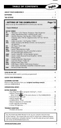
INPUT CONNECTIONS AND AUDIO CONTROL<br />
Figure 1-1 <strong>EAPA</strong>250 Input Connections and audio control<br />
Figure 1-2 <strong>EAPA</strong>450 Input connections and Audio Control<br />
1. RCA Input Jacks 9. Front Speaker Level Inputs<br />
2. Front RCA input Jacks 10. Rear Speaker Level Inputs<br />
3. Rear RCA Input Jacks 11. Frequency Control<br />
4. Gain Control 12. X-over Mode Switch<br />
5. Front Gain Control 13. Front Frequency Control<br />
6. Rear Gain Control 14. Front X-over Mode Switch<br />
7. Bass Boost Control 15. Rear Frequency Control<br />
8. Speaker Level Inputs 16. Rear X-over Mode Switch<br />
The Input Connections are gold-plated RCA Jacks. The Gain Controls provide a wide adjustment<br />
range to accommodate output levels from any source unit brand.<br />
Gain Controls – Gain Controls allow you to set the nominal operation level of the amplifier. The<br />
amplifier’s range, 250mV to 2.5V for RCA inputs or 500mB to 5V for speaker level inputs, can<br />
accommodate input levels from virtually any source unit brand.<br />
Bass Boost Control - The amplifier also features a “high-Q” (i.e., narrow frequency band) Bass<br />
Boost circuit. It acts much like an equalizer with a switch-able gain fixed at 45Hz. Use this feature<br />
to tune low-frequency audio response to compensate for a less than ideal subwoofer enclosure design.<br />
The added boost produces rich, full bass tones that are normally difficult to reproduce in the car audio<br />
environment. NOTE: If Bass Boost is undesired, set Bass Boost to OFF.<br />
-3-<br />
High-Pass / Low-Pass Filter Controls<br />
Freq (HZ) Controls – The crossover frequency is fully adjustable between 50Hz and 250 Hz. Use<br />
this feature, along with your speaker manufacturers recommended crossover frequencies, to quickly<br />
design a more advanced system. NOTE: IF either of the X-over Mode Switches is set to OFF,<br />
varying the Freq (HZ) Control will product no effect.<br />
X-Over Mode Switches - These switches are equipped with 12dB per octave electronic filters for<br />
precise frequency attenuation with minimal phase distortion. Each filter is activated by sliding the<br />
X-Over Mode Switch to either HP or LP.<br />
• Speaker Level Inputs - These provide connections for a high-level stereo source. These<br />
connections are provided for installations when the source unit does not have RCA outputs.<br />
WARNING: When using the speaker (high-level) inputs, the Black wire must be grounded at the<br />
radio. Failure to do so will result in noise and/or improper operation.<br />
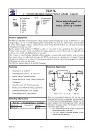
CONNECTIONS FOR POWER AND SPEAKERS<br />
Figure 2-1 <strong>EAPA</strong>250 Connections for Power and speakers<br />
Figure 2-2 <strong>EAPA</strong>450 Connections for Power and speakers<br />
1. Left front speaker output 6. Ground Input<br />
2. Right front speaker output 7. Battery + 12V input<br />
3. Left speaker output 8. Fuse<br />
4. Right speaker output 9. Left rear speaker output<br />
5. Remote turn-on input 10. Right rear speaker output<br />
-4-
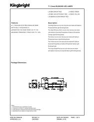
APPLICATIONS<br />
This <strong>EAPA</strong>250 2-channel car audio amplifier can be used in a variety of system applications. Here<br />
are some examples to help plan your own installation.<br />
Bridged mono subwoofer system<br />
Figure 3 – In this application, the amplifier is bridged for mono operation to drive a subwoofer<br />
-5-<br />
-6-
SETTING THE GAIN<br />
After completing the installation, follow these steps to set the Gain Control and then perform the<br />
Final System Checks.<br />
1. Turn the Gain Control all the way counter-clockwise.<br />
2. Turn the vehicle’s Ignition Switch to the ON position. Then turn the ON/OFF<br />
Switch on the source unit to the ON position. Set all Tone or Equalization Controls to “flat” positions<br />
and turn Loudness off.<br />
3. Play a CD or Tape and set the Volume Control at 75% of full level.<br />
NOTE: If the system uses an equalizer set all frequency controls to the “flat” position.<br />
4. Slowly increase the Gain Control. Stop when you hear a slight distortion of audio.<br />
SETTING THE CROSSOVER<br />
1. Using the X-Over Mode Switch, select the desired mode: LP for Low Pass, HP for High Pass or<br />
-7-<br />
OFF for Full Range.<br />
2. Using the Freq (Hz) Selection Control, select the desired frequency.<br />
SETTING THE BASS BOOST<br />
1. Initially set the Bass Boost control to its OFF position.<br />
2. Listen to a variety of music styles (e.g., Rock, Rap, etc.) and switch the Bass Boost control ON<br />
until a noticeable increase in low bass response is realized.<br />
CAUTION: If you hear a “pop” (due to speaker over-excursion) adjust switch to lower the Bass<br />
Boost to prevent speaker damage.<br />
FINAL SYSTEM CHECKS<br />
1. Start the engine and turn on the source unit. After a two-second delay, slowly increase the volume<br />
control and listen to the audio. If you hear any noise, static, distortion or no sound at all, check the<br />
connections, and also refer to troubleshooting section below. Depending on your system design, the<br />
levels may become quite loud even at low volume control settings. Until you get an “audio feel” of<br />
the system’s power, use care when adjusting controls.<br />
2. Turn the balance controls to their extreme positions and listen to the results. Audio output should<br />
match control settings (audio from the left speaker when balance is left).<br />
3. Increase the volume and verify that the amplifier reproduces audio (at full frequencies) without<br />
distortion. If you hear distortion, check the connections and verify that the gain control is set correctly.<br />
Another possibility is damaged speakers or underpowered speakers. Once again refer to<br />
troubleshooting section for additional help.<br />
TROUBLESHOOTING<br />
PROBLEM POSSIBLE CAUSE SOLUTION<br />
AUDIO CYCLES<br />
ON AND OFF<br />
NO AUDIO<br />
THERMAL PROTECTION<br />
CIRCUITS ARE SHUTTING<br />
AMPLIFIER OFF<br />
LOW OR NO REMOTE<br />
TURN-ON VOLTAGE<br />
CHECK LOCATION FOR ADEQUATE<br />
VENTILATION; CONSULT AN AUTHORIZED<br />
CLARION AUDIO DEALER.<br />
CHECK REMOTE CONNECTIONS AT AMPLIFIER<br />
AND SOURCE UNIT.<br />
BLOWN AMPLIFIER FUSE REPLACE WITH NEW FAST-BLOW FUSE (SAME<br />
RATING).<br />
POWER WIRES NOT<br />
CHECK BATTERY AND GROUND WIRING AT<br />
CONNECTED<br />
AMPLIFIER; ALSO CHECK BATTERY<br />
CONNECTIONS.<br />
SPEAKER LEADS SHORTED CHECK SPEAKER CONTINUITY TO GROUND, IT<br />
SHOULD NOT SHOW A COMMON GROUND.<br />
SPEAKERS NOT<br />
CHECK SPEAKER CONNECTIONS AT AMPLIFIER,<br />
CONNECTED OR ARE<br />
BLOWN<br />
MEASURE COIL IMPEDANCE.<br />
WHINING OR AMPLIFIER IS PICKING UP TURN DOWN INPUT GAIN AND MOVE AUDIO<br />
TICKING NOISE ALTERNATION NOISE OR CABLES AWAY FROM POWER WIRES. CHECK<br />
IN THE AUDIO RADIATED NOISE<br />
POWER AND GROUND CONNECTIONS ON<br />
WITH ENGINE<br />
AMPLIFIER AND INSTALL AN IN-LINE NOISE<br />
ON.<br />
FILTER ON SOURCE UNIT’S POWER WIRE.<br />
ALSO CHECK THE ALTERNATOR AND /OR<br />
VOLTAGE. TEST FOR WEAK BATTERY OR ADD<br />
WATER TO BATTERY.<br />
DISTORTED GAIN IS NOT SET<br />
REVIEW SETTING GAIN; INSPECT EACH<br />
AUDIO.<br />
PROPERLY, OR DAMAGED SPEAKER CONE FOR SIGNS OF DAMAGE (I.E.,<br />
SPEAKER CONES<br />
FROZEN CONE, BURNING SMELL, ETC.)<br />
AMPLIFIER FUSE INCORRECT WIRING OR REVIEW INSTALLATION AND CHECK ALL<br />
KEEPS BLOWING SHORT CIRCUIT<br />
-8-<br />
WIRING CONNECTION.