Module 8067-1.pdf filesize - Maplin Electronics
Module 8067-1.pdf filesize - Maplin Electronics
Module 8067-1.pdf filesize - Maplin Electronics

You also want an ePaper? Increase the reach of your titles
YUMPU automatically turns print PDFs into web optimized ePapers that Google loves.
Application Information<br />
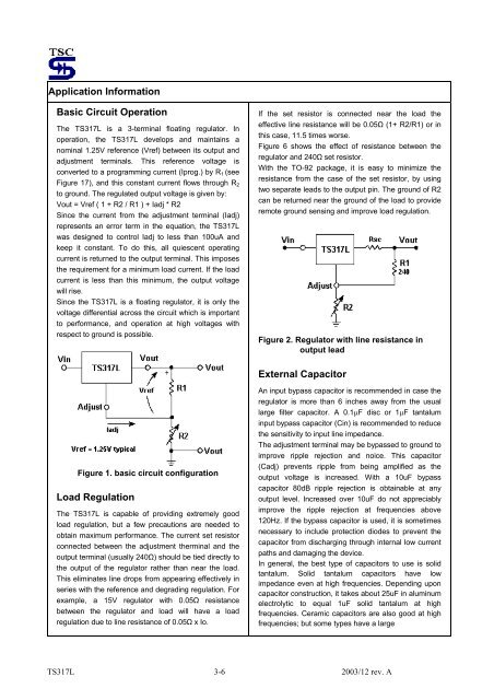
Basic Circuit Operation<br />
The TS317L is a 3-terminal floating regulator. In<br />
operation, the TS317L develops and maintains a<br />
nominal 1.25V reference (Vref) between its output and<br />
adjustment terminals. This reference voltage is<br />
converted to a programming current (Iprog.) by R1 (see<br />
Figure 17), and this constant current flows through R2<br />
to ground. The regulated output voltage is given by:<br />
Vout = Vref ( 1 + R2 / R1 ) + Iadj * R2<br />
Since the current from the adjustment terminal (Iadj)<br />
represents an error term in the equation, the TS317L<br />
was designed to control Iadj to less than 100uA and<br />
keep it constant. To do this, all quiescent operating<br />
current is returned to the output terminal. This imposes<br />
the requirement for a minimum load current. If the load<br />
current is less than this minimum, the output voltage<br />
will rise.<br />
Since the TS317L is a floating regulator, it is only the<br />
voltage differential across the circuit which is important<br />
to performance, and operation at high voltages with<br />
respect to ground is possible.<br />
Figure 1. basic circuit configuration<br />
Load Regulation<br />
The TS317L is capable of providing extremely good<br />
load regulation, but a few precautions are needed to<br />
obtain maximum performance. The current set resistor<br />
connected between the adjustment therminal and the<br />
output terminal (usually 240Ω) should be tied directly to<br />
the output of the regulator rather than near the load.<br />
This eliminates line drops from appearing effectively in<br />
series with the reference and degrading regulation. For<br />
example, a 15V regulator with 0.05Ω resistance<br />
between the regulator and load will have a load<br />
regulation due to line resistance of 0.05Ω x Io.<br />
If the set resistor is connected near the load the<br />
effective line resistance will be 0.05Ω (1+ R2/R1) or in<br />
this case, 11.5 times worse.<br />
Figure 6 shows the effect of resistance between the<br />
regulator and 240Ω set resistor.<br />
With the TO-92 package, it is easy to minimize the<br />
resistance from the case of the set resistor, by using<br />
two separate leads to the output pin. The ground of R2<br />
can be returned near the ground of the load to provide<br />
remote ground sensing and improve load regulation.<br />
Figure 2. Regulator with line resistance in<br />
output lead<br />
External Capacitor<br />
An input bypass capacitor is recommended in case the<br />
regulator is more than 6 inches away from the usual<br />
large filter capacitor. A 0.1µF disc or 1µF tantalum<br />
input bypass capacitor (Cin) is recommended to reduce<br />
the sensitivity to input line impedance.<br />
The adjustment terminal may be bypassed to ground to<br />
improve ripple rejection and noice. This capacitor<br />
(Cadj) prevents ripple from being amplified as the<br />
output voltage is increased. With a 10uF bypass<br />
capacitor 80dB ripple rejection is obtainable at any<br />
output level. Increased over 10uF do not appreciably<br />
improve the ripple rejection at frequencies above<br />
120Hz. If the bypass capacitor is used, it is sometimes<br />
necessary to include protection diodes to prevent the<br />
capacitor from discharging through internal low current<br />
paths and damaging the device.<br />
In general, the best type of capacitors to use is solid<br />
tantalum. Solid tantalum capacitors have low<br />
impedance even at high frequencies. Depending upon<br />
capacitor construction, it takes about 25uF in aluminum<br />
electrolytic to equal 1uF solid tantalum at high<br />
frequencies. Ceramic capacitors are also good at high<br />
frequencies; but some types have a large<br />
TS317L 3-6 2003/12 rev. A