

34169522 - heidenhain - DR. JOHANNES HEIDENHAIN GmbH
34169522 - heidenhain - DR. JOHANNES HEIDENHAIN GmbH
34169522 - heidenhain - DR. JOHANNES HEIDENHAIN GmbH

You also want an ePaper? Increase the reach of your titles
YUMPU automatically turns print PDFs into web optimized ePapers that Google loves.
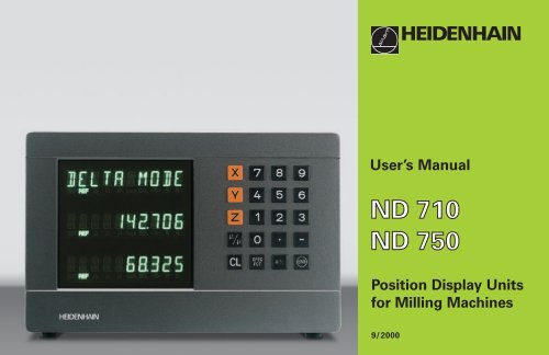
User’s Manual<br />
Position Display Units<br />
for Milling Machines<br />
9/2000
Status display:<br />
SET = Datum setting<br />
REF = blinking:<br />
Traverse the<br />
reference points.<br />
On continuously:<br />
Reference points<br />
have been traversed.<br />
∆ = Distance-to-go display<br />
1 2 Datum 1 or 2<br />
Inch = Display in inches<br />
SCL = Scaling factor<br />
->❘❘
This manual is for the ND display units with the<br />
following software numbers or higher:<br />
ND 710 for two axes 246 271-06<br />
ND 750 for three axes 246 271-06<br />
About this manual<br />
This manual is divided into two parts:<br />
Part I: Operating Instructions<br />
Fundamentals of positioning<br />
ND functions<br />
Part II: Installation and Specifications<br />
Mounting the display unit on the machine<br />
Description of operating parameters<br />
Part I Operating Instructions<br />
Fundamentals 4<br />
Switch-On, Traversing the Reference Points 9<br />
Datum Setting 10<br />
Tool Compensation 19<br />
Moving the Axes with Distance-To-Go 20<br />
Bolt Hole Circles and Bolt Hole Circle Segments 22<br />
Linear Hole Patterns 25<br />
Working with a Scaling Factor 28<br />
Error Messages 29<br />
Part II<br />
Installation and<br />
Specifications Page 31<br />
Part I Operating Instructions<br />
3
Fundamentals<br />
4<br />
Fundamentals<br />
You can skip this chapter if you are already familiar with<br />
coordinate systems, incremental and absolute dimensions,<br />
nominal positions, actual positions and distance-to-go.<br />
Coordinate system<br />
To describe the geometry of a workpiece, the Cartesian* coordinate<br />
system is used. The Cartesian coordinate system consists of three<br />
mutually perpendicular axes X, Y and Z. The point of intersection of<br />
these axes is called the datum or origin of the coordinate system.<br />
Think of the axes as scales with divisions (usually in millimeters) which<br />
allow us to fix points in space referenced to the datum.<br />
To determine positions on a workpiece, the coordinate system is<br />
“ laid” onto the workpiece.<br />
The machine axes are parallel to the axes of the coordinate system.<br />
The Z axis is normally the tool axis.<br />
1) Named in honor of the French mathematician and philosopher<br />
René Descartes (1596 to 1650)<br />
Y<br />
+Y<br />
Z<br />
+Z<br />
–X Datum or<br />
origin<br />
–Z<br />
Graduation<br />
–Y<br />
X<br />
+X
Datum setting<br />
The workpiece drawing is used as the basis for machining the<br />
workpiece. To enable the dimensions in the drawing to be converted<br />
into traverse distances of machine axes X, Y and Z, each drawing<br />
dimension requires a datum or reference point on the workpiece<br />
(since a position can only be defined in relationship to another<br />
position).<br />
The workpiece drawing always indicates one absolute datum (the<br />
datum for absolute dimensions). However, it may contain additional<br />
relative datums.<br />
In the context of a numerical position display unit, datum setting<br />
means bringing the workpiece and the tool into a defined position in<br />
relation to each other and then setting the axis displays to the value<br />
which corresponds to that position. This establishes a fixed<br />
relationship between the actual positions of the axes and the<br />
displayed positions.<br />
You can set 2 absolute datum points and store them in nonvolatile<br />
memory.<br />
1225<br />
750<br />
320<br />
0<br />
Absolute<br />
datum<br />
0<br />
300±0,1<br />
150<br />
0<br />
-150<br />
325<br />
-250<br />
-216,5<br />
-125<br />
0<br />
125<br />
216,5<br />
250<br />
0<br />
450<br />
700<br />
900<br />
950<br />
216,5<br />
125<br />
0<br />
-125<br />
-216,5<br />
250<br />
Relative<br />
datums<br />
-250<br />
Fundamentals<br />
5
Fundamentals<br />
6<br />
Absolute workpiece positions<br />
Each position on the workpiece is uniquely defined by its absolute<br />
coordinates.<br />
Example Absolute coordinates of position 1:<br />
X = 10 mm<br />
Y = 5 mm<br />
Z = 0 mm<br />
If you are working according to a workpiece drawing with absolute<br />
dimensions, then you are moving the tool to the coordinates.<br />
Relative workpiece positions<br />
A position can also be defined relative to the previous nominal<br />
position. The datum for the dimension is then located at the<br />
previous nominal position. Such coordinates are termed relative<br />
coordinates or chain dimensions. Incremental coordinates are<br />
indicated by a preceding I.<br />
Example Relative coordinate of position 2 referenced to<br />
position 1:<br />
IX = 10 mm<br />
IY = 10 mm<br />
If you are working according to a workpiece drawing with<br />
incremental dimensions, then you are moving the tool by the<br />
dimensions.<br />
Sign for incremental dimensioning<br />
A relative dimension has a positive sign when the axis is moved<br />
in the positive direction, and a negative sign when it is moved<br />
in the negative direction.<br />
Y<br />
Y<br />
5<br />
5<br />
Z<br />
Z<br />
10<br />
1<br />
1<br />
1<br />
2<br />
10<br />
10<br />
10<br />
X<br />
X
Nominal position, actual position and distance-to-go<br />
The position to which the tool is to move is called the nominal<br />
position ( S ). The position at which the tool is actually located at any<br />
given moment is called the actual position ( I ).<br />
The distance from the nominal position to the actual position is called<br />
the distance-to-go ( R ).<br />
Sign for distance-to-go<br />
When you are using the distance-to-go display, the nominal position<br />
becomes the relative datum (display value 0). The distance-to-go is<br />
therefore negative when you move in the positive axis direction, and<br />
positive when you move in the negative axis direction.<br />
Y<br />
Z<br />
I<br />
R<br />
S<br />
X<br />
Fundamentals<br />
7
Fundamentals<br />
8<br />
Position encoders<br />
The position encoders on the machine convert the movements of the<br />
machine axes into electrical signals. The ND display unit evaluates<br />
these signals, determines the actual position of the machine axes and<br />
displays the position as a numerical value.<br />
If the power is interrupted, the relationship between the machine axis<br />
positions and the calculated actual positions is lost. The reference<br />
marks on the position encoders and the REF reference mark<br />
evaluation feature enable the ND to quickly re-establish this<br />
relationship again when the power is restored.<br />
Reference marks<br />
The scales of the position encoders contain one or more reference<br />
marks. When a reference mark is crossed over, a signal is generated<br />
which identifies that position as a reference point (scale datum =<br />
machine datum).<br />
When this reference mark is crossed over, the ND's reference mark<br />
evaluation feature (REF) restores the relationship between axis slide<br />
positions and display values which you last defined by setting the<br />
datum. If the linear encoders have distance-coded reference marks,<br />
you only need to move the machine axes a maximum of 20 mm to do<br />
this.<br />
Y<br />
Z<br />
Workpiece<br />
X<br />
Position<br />
encoder<br />
Scale in Distance-coded<br />
linear encoder reference marks<br />
Reference mark
Switch-On, Traversing the Reference Marks<br />
Turn on power (switch located on rear panel).<br />
0 è 1 REF and decimal points in status display blink.<br />
Marks<br />
ENT...CL<br />
ENT Confirm reference traverse mode. REF remains<br />
on continuously. Decimal points blink.<br />
Reference the<br />
Cross over the reference marks in all axes (in any<br />
sequence). Each axis display becomes active<br />
when its reference mark is crossed over.<br />
Crossing over the reference marks stores the last relationship<br />
Traversing<br />
between axis slide positions and display values for datum points 1 and<br />
2 in nonvolatile memory.<br />
Note that if you choose not to traverse the reference marks (by<br />
clearing the dialog ENT ... CL with the CL key), this relationship will be<br />
lost if the power is interrupted or when the unit is switched off. Switch-On,<br />
If you wish to use multipoint axis error compensation you<br />
must traverse the reference marks (see “ Multipoint axis error<br />
compensation” )!<br />
9
Datum Setting<br />
10<br />
Datum Setting<br />
If you want to save the datum points in nonvolatile<br />
memory, you must first cross over the reference<br />
marks.<br />
Only after crossing over the reference marks can you set new<br />
datums or activate existing ones.<br />
In P70, you can select:<br />
Two datum points: The selected datum<br />
is displayed via 1 or 2<br />
Nine datum points: The selected datum<br />
is displayed in the lowest axis via d1 to d9.<br />
There are several ways to set datums:<br />
Touch the edge of the workpiece with the tool and then set<br />
the desired datum. You can also touch two edges and set the<br />
centerline between them as a datum, or touch the inside of a<br />
circle and set the circle center as a datum (see examples).<br />
The tool data of the tool used for this are automatically<br />
considered (see “ Tool Compensation” ).<br />
To call a datum point you have set, proceed as follows:<br />
You have set two datum points in P70:<br />
1 ENT<br />
Select datum 1 or 2.<br />
You have set nine datum points in P70:<br />
Press the datum key (“ d” blinks).<br />
Enter a datum number (1 to 9).
Probing a workpiece edge to find a datum<br />
The ND display units support the following probing functions:<br />
“ PROBE EDGE” Setting a workpiece edge as datum.<br />
“ PROBE MIDPOINT” Setting a midpoint between two<br />
workpiece edges as datum.<br />
“ PROBE CIRCLE” Setting the center of a circle as datum.<br />
The probing functions are accessible in the SPEC FCT mode of<br />
operation.<br />
The functions “ PROBE EDGE” , “ PROBE MIDPOINT” and “ PROBE<br />
CIRCLE” are described on the following pages.<br />
Datum setting with the tool<br />
Example:<br />
Working plane X / Y<br />
Tool axis Z<br />
Tool radius R = 5 mm<br />
Axis sequence X – Y – Z<br />
for datum setting<br />
Y<br />
Z<br />
1<br />
2<br />
R=5mm<br />
X<br />
Datum Setting<br />
11
Datum Setting<br />
12<br />
Probing a workpiece edge to find a datum<br />
SPEC<br />
FCT<br />
SPEC<br />
FCT<br />
or<br />
PROBING<br />
ENT<br />
PROBE EDGE<br />
ENT<br />
X<br />
Select a datum number (see<br />
page 10).<br />
Select the special functions.<br />
Select “ probing function.”<br />
Confirm selection.<br />
Confirm “ Probe edge.”<br />
Select the X axis (if not already selected).<br />
SET lights. The ❘
ENT<br />
0 ENT<br />
Z<br />
PROBE Z (appears only briefly)<br />
ENT<br />
1) only with ND 750<br />
Y position is captured. “ SET<br />
edge“ appears briefly. SET starts to blink.<br />
Retract tool from workpiece.<br />
The ❘
Datum Setting<br />
14<br />
Probing workpiece edges to find a midpoint datum<br />
The edges to be probed run parallel to the Y axis.<br />
Follow the procedure below for all midpoints between two edges:<br />
SPEC<br />
FCT<br />
SPEC<br />
FCT<br />
or<br />
PROBING<br />
ENT<br />
Select a datum number (see page 10).<br />
Select the special functions.<br />
Select the probing function.<br />
Confirm selection.<br />
Y<br />
1<br />
Z<br />
2<br />
M X?<br />
X
PROBE EDGE<br />
ANTASTEN or MITTE<br />
PROBE MIDP.<br />
X<br />
ENT<br />
Select the X axis (if not already selected)<br />
and confirm with ENT. The ->❘❘
Datum Setting<br />
16<br />
Probing the inside of a circle to set its center as datum<br />
To determine the circle center, the tool must probe four points.<br />
The points to be probed are located in the X-Y plane.<br />
SPEC<br />
FCT<br />
PROBING<br />
SPEC<br />
FCT<br />
or<br />
ENT<br />
PROBE CIRC.<br />
ANTASTEN or MITTE<br />
Select a datum number (see page 10).<br />
Select the special functions.<br />
Select the probing function.<br />
Confirm selection.<br />
Select “ Probe circle.”<br />
Y<br />
0<br />
2<br />
3 4<br />
1<br />
X?<br />
X
PROBE CIRC.<br />
ENT<br />
1ST POS X (appears only briefly)<br />
ENT<br />
Confirm “ Probe circle.”<br />
Touch workpiece at position 1 with the<br />
tool.<br />
Position 1 is captured.<br />
Retract tool from workpiece.<br />
2ND POS X (appears only briefly)<br />
Touch workpiece at position 2 with the<br />
tool.<br />
ENT<br />
3RD POS Y (appears only briefly)<br />
ENT<br />
Position 2 is captured.<br />
Retract tool from workpiece.<br />
Touch workpiece at position 3 with the<br />
tool.<br />
Position 3 is captured.<br />
Retract tool from workpiece.<br />
Datum Setting<br />
17
Datum Setting<br />
18<br />
4TH POS Y (appears only briefly)<br />
Touch workpiece at position 4 with<br />
the tool.<br />
2 6<br />
SPEC<br />
FCT<br />
ENT<br />
0 ENT<br />
or<br />
ENT<br />
CL<br />
Position 4 is captured. “ CENTER X”<br />
appears briefly. Status display SET<br />
starts to blink in the X axis.<br />
Enter position value for the X coordinate<br />
of circle center, e.g. 26. “ CENTER Y”<br />
appears briefly. Status display SET starts<br />
to blink in the Y axis.<br />
Enter position value for the Y coordinate<br />
of circle center, e.g. 0.<br />
Exit the probing functions.
Tool Compensation<br />
You can enter the axis, length and diameter of the current tool.<br />
SPEC<br />
FCT<br />
SPEC<br />
FCT<br />
TOOL DATA<br />
ENT<br />
TOOL DIAM.<br />
2 0<br />
TOOL LENGTH<br />
5<br />
or<br />
ENT<br />
0 ENT<br />
1) only with ND 750<br />
Select the special functions.<br />
Select “ tool data.”<br />
Confirm tool data input mode.<br />
Enter the tool diameter, e.g. 20 mm,<br />
and confirm with ENT.<br />
Enter the tool length, e.g. 50 mm, and<br />
confirm with ENT.<br />
1)<br />
TOOL AXIS<br />
Z<br />
TOOL AXIS<br />
SPEC or<br />
FCT CL<br />
Set the tool axis.<br />
Exit the special functions.<br />
Tool Compensation<br />
19
Moving the Axes with Distance-To-Go Display<br />
20<br />
Moving the Axes with Distance-To-Go Display<br />
Normally, the display shows the actual position of the tool. However, it<br />
is often more helpful to display the distance remaining to the nominal<br />
position (the distance-to-go). You can then position simply by moving<br />
the axis until the display value is zero.<br />
You can enter the absolute coordinates in the distance-to-go display.<br />
An active radius compensation will be considered.<br />
Example: Milling a shoulder with distance-to-go<br />
SPEC<br />
FCT<br />
SPEC or<br />
FCT<br />
DELTA MODE<br />
ENT<br />
Y 2 0<br />
ENT<br />
R + -<br />
Select the special functions.<br />
Select “ delta mode.”<br />
Confirm your selection, the ∆ symbol lights.<br />
Select the axis, enter the nominal value,<br />
e.g. 20 mm, select radius compensation R+,<br />
confirm with ENT.
X 3 0<br />
R + -<br />
Y 5 0<br />
R + -<br />
SPEC<br />
FCT<br />
or<br />
R + -<br />
ENT<br />
ENT<br />
ENT<br />
CL<br />
Move the machine axis to zero 1.<br />
Select the axis, enter the nominal value,<br />
e.g. 30 mm, select radius compensation<br />
R– , and confirm with ENT.<br />
Move the machine axis to zero 2.<br />
Select the axis, enter the nominal<br />
value, e.g. 50 mm, select radius<br />
compensation R+, confirm with ENT.<br />
Move the machine axis to zero 3.<br />
If appropriate, switch off the distanceto-go<br />
display.<br />
Moving the Axes with Distance-To-Go Display<br />
21
Bolt Hole Circles/Bolt Hole Circle Segments<br />
22<br />
Bolt Hole Circles and Bolt Hole Circle Segments<br />
Your display unit enables you to quickly and easily drill bolt hole circles<br />
and bolt hole circle segments. The required data is requested in the<br />
message field.<br />
Each hole can be moved to by traversing to display value zero. This<br />
requires entry of the following data:<br />
Number of holes (maximum: 999)<br />
Circle center<br />
Circle radius<br />
Starting angle for first hole<br />
Angle step between the holes (only for circle segments)<br />
Hole depth<br />
Example<br />
Number of holes 8<br />
Coordinates of the center X = 50 mm<br />
Y = 50 mm<br />
Circle radius 20 mm<br />
Starting angle 30 degrees<br />
Hole depth Z = – 5 mm<br />
50<br />
0<br />
Y<br />
0<br />
R20<br />
50<br />
30°<br />
X
SPEC<br />
FCT<br />
SPEC<br />
FCT<br />
BOLT HOLE<br />
FULL CIRCLE<br />
if req.<br />
ENT<br />
NUMB. HOLES<br />
8<br />
or<br />
ENT<br />
ENT<br />
Select the special functions.<br />
Select “ bolt hole” circle.<br />
Confirm your selection.<br />
Confirm “ full circle.”<br />
Enter the number of holes, e.g. 8.<br />
Confirm with ENT.<br />
CENTER X<br />
X 5 0<br />
CENTER Y<br />
Y<br />
RADIUS<br />
2<br />
5 0<br />
0<br />
START ANGLE<br />
3<br />
ENT<br />
ENT<br />
ENT<br />
ENT<br />
0<br />
Enter the X coordinate of circle center,<br />
e.g. 50 mm, confirm with ENT.<br />
Enter the Y coordinate of circle center,<br />
e.g. 50 mm, confirm with ENT.<br />
Enter the radius of the bolt hole circle,<br />
e.g. 20 mm. Confirm with ENT.<br />
Enter the start angle for the first hole,<br />
e.g. 30°. Confirm with ENT.<br />
Bolt Hole Circles/Bolt Hole Circle Segments<br />
23
Bolt Hole Circles/Bolt Hole Circle Segments<br />
24<br />
HOLE DEPTH<br />
Z<br />
START<br />
SPEC<br />
FCT<br />
ENT<br />
5<br />
ENT<br />
ENT<br />
or CL<br />
1) only with ND 750<br />
Enter the total hole depth, e.g. – 5 mm, and<br />
confirm with ENT.<br />
Start the display of the hole positions.<br />
After the start, the distance-to-go mode becomes<br />
active ( the ∆ symbol lights). The hole number is<br />
shown briefly in the X axis. The individual holes<br />
are reached by traversing to zero. The holes can<br />
be selected with the ENT key or the 1 2 key.<br />
The minus key shows the hole number again.<br />
Exit the bolt hole circle function.<br />
1)
Linear Hole Patterns<br />
The linear hole pattern feature allows you to easily create rows of<br />
holes to cover an area. The required data are requested in the<br />
message field.<br />
You can position to each hole by traversing to display value zero.<br />
The following data are required:<br />
Coordinates of the first hole<br />
Number of holes per row (maximum: 999)<br />
Spacing between holes<br />
Angle between the rows and the reference axis<br />
Hole depth<br />
Number of rows (maximum: 999)<br />
Spacing between rows<br />
Example<br />
Coordinates of the first hole X = 20 mm<br />
Y = 15 mm<br />
Number of holes per row 4<br />
Spacing between holes 16 mm<br />
Angle 15 degrees<br />
Hole depth Z = – 30 mm<br />
Number of rows 3<br />
Spacing between rows 20 mm<br />
15<br />
0<br />
Y<br />
0<br />
9<br />
5<br />
1<br />
20<br />
16<br />
6<br />
2<br />
7<br />
12<br />
3<br />
8<br />
15°<br />
4<br />
20<br />
X<br />
Linear Hole Patterns<br />
25
Linear Hole Patterns<br />
26<br />
SPEC<br />
FCT<br />
SPEC<br />
FCT<br />
LIN. HOLE<br />
ENT<br />
1ST HOLE X<br />
2<br />
0<br />
1ST HOLE Y<br />
1<br />
or<br />
5<br />
ENT<br />
ENT<br />
1) only with ND 750<br />
Select the special functions.<br />
Select “ hole pattern.”<br />
Confirm “ linear hole” pattern.<br />
Enter the X coordinate of the first holes,<br />
e.g. 20, and confirm with ENT.<br />
Enter the Y coordinate of the first holes,<br />
e.g. 15, and confirm with ENT.<br />
HOLES ROW<br />
4<br />
HOLE SPACE<br />
1<br />
ANGLE<br />
ENT<br />
6<br />
1 5<br />
ENT<br />
HOLE DEPTH<br />
3 0<br />
ENT<br />
ENT<br />
Enter the number of holes per row,<br />
e.g. 4, and confirm with ENT.<br />
Enter the spacing between holes in the<br />
row, e.g. 16, and confirm with ENT.<br />
Enter the angle, e.g. 15 degrees,<br />
and confirm with ENT.<br />
Enter the hole depth, e.g. – 30 mm,<br />
and confirm with ENT.<br />
1)
NUMBER ROW<br />
3<br />
ROW SPACE<br />
2<br />
START<br />
ENT<br />
SPEC<br />
FCT<br />
0<br />
ENT<br />
ENT<br />
ENT<br />
or CL<br />
Enter the number of rows, e.g. 3,<br />
and confirm with ENT.<br />
Enter the spacing of the rows, e.g. 20,<br />
and confirm with ENT.<br />
Start the display of hole positions.<br />
The distance-to-go mode is now active<br />
(the ∆ symbol lights). The hole number is shown<br />
briefly in the X axis. Move to the individual hole<br />
positions by traversing to the display value zero.<br />
Hole can be selected with the ENT key or with<br />
the 1 2 key. Pressing the minus key shows the<br />
hole number again.<br />
Exit the linear hole patterns function.<br />
Linear Hole Patterns<br />
27
Scaling Factor<br />
28<br />
Working with a Scaling Factor<br />
Scaling factors enable you to increase or decrease the display values<br />
based on the actual traverse distance. The display values are changed<br />
symmetrically about the datum.<br />
Enter scaling factors separately for each axis in parameter P12.<br />
Parameter P11 activates and deactivates the scaling factors in all axes<br />
(see “ Operating Parameters” ).<br />
Example for enlarging a workpiece:<br />
P12.1 3.5<br />
P12.2 3.0<br />
P11 ON<br />
This results in a larger workpiece as shown in the illustration at right:<br />
1 is the original size, 2 is with axis-specific scaling factors.<br />
If a scaling factor is active, SCL lights in the status display.<br />
0<br />
Y<br />
0<br />
∗ 3.0<br />
1<br />
2<br />
∗ 3.5<br />
X
Error Messages<br />
Message Cause and effect<br />
SIGNAL X Encoder signal is too small,<br />
e.g. when an encoder is<br />
contaminated.<br />
PROB. ERROR Before touching off on the<br />
workpiece, the tool must move<br />
by a distance of at least 0.2 mm.<br />
ERR. REF. X The spacing of the reference<br />
marks as defined in P43 is not<br />
the same as the actual spacing.<br />
FRQ. ERR. X The input frequency for this<br />
encoder input is too high. This<br />
can occur when the scale is<br />
moved too fast.<br />
ERR. MEMORY Check sum error: Check the<br />
datum, operating parameters and<br />
compensation values for multipoint<br />
axis error compensation.<br />
If the error recurs, contact your<br />
service agency!<br />
To erase error messages:<br />
After you have removed the cause of error:<br />
➤ Press the CL key.<br />
Error Messages<br />
29
Part II Installation and<br />
Specifications<br />
Items Supplied 32<br />
Connections on Rear Panel 33<br />
Mounting 34<br />
Power Connection 34<br />
Connecting the Encoders 35<br />
Operating Parameters 36<br />
Entering/changing operating parameters 36<br />
Operating parameter list 37<br />
Linear Encoders 39<br />
Setting the display step 39<br />
Display step, signal period, and subdivision<br />
Parameter settings for <strong>HEIDENHAIN</strong> linear encoders<br />
39<br />
with 11 µApp 40<br />
Multipoint Axis Error Compensation 41<br />
Specifications 44<br />
Dimensions of the ND 710/ND 750 45<br />
Part II Installation and Specifications<br />
31
Items Supplied<br />
32<br />
Items Supplied<br />
ND 710 for 2 axes<br />
or<br />
ND 750 for 3 axes<br />
Power connector Id. Nr. 257 811-01<br />
User's Manual<br />
Optional Accessories<br />
Tilting base for housing bottom<br />
Id. Nr. 281 619-01
Connections on Rear Panel<br />
ID label<br />
Power switch<br />
Power input<br />
Protective ground Encoder inputs X1 to X3 Rubber feet with M4 thread<br />
The interfaces X1, X2, X3 comply with the requirements for electrical separation according to EN 50178!<br />
Connections on Rear Panel<br />
33
Mounting/Power Connection<br />
34<br />
Mounting<br />
ND 710/ND 750<br />
To mount the display unit on a support, use the M4 threaded holes in<br />
the rubber feet. You can also mount the display unit on the optional<br />
tilting base.<br />
Power Connection<br />
Power leads: L and N<br />
Connect protective ground to !<br />
Power supply: 100 Vac to 240 Vac (-15 % to +10 %)<br />
50 Hz to 60 Hz (± 2 Hz)<br />
A voltage selector is not necessary.<br />
Danger of electrical shock!<br />
Connect a protective ground. This connection must never<br />
be interrupted.<br />
Unplug the power cord before opening the housing.<br />
To increase the noise immunity, connect the ground terminal<br />
on the rear panel to the central ground point of the machine.<br />
(Minimum cross-section: 6 mm 2 ).<br />
Tilting base<br />
Support<br />
<strong>HEIDENHAIN</strong>
Connecting the Encoders<br />
Your display unit will accept all <strong>HEIDENHAIN</strong> linear encoders with<br />
sinusoidal output signals (7 to 16 µApp) and distance-coded or single<br />
reference marks.<br />
Assignment of the encoder inputs<br />
Encoder input X1 is for the X axis.<br />
Encoder input X2 is for the Y axis.<br />
Encoder input X3 is for the Z axis (ND 750 only).<br />
Encoder monitoring system<br />
Your display unit features a monitoring system for checking the<br />
amplitude and frequency of the encoder signals. If it detects a faulty<br />
signal, one of the following error messages will be generated:<br />
SIGNAL X<br />
FRQ. X<br />
Encoder monitoring can be activated with parameter P45.<br />
If you are using linear encoders with distance-coded reference marks,<br />
the encoder monitoring system also checks whether the spacing of<br />
the reference marks as defined in parameter P43 is the same as the<br />
actual spacing on the scales. If it is not, the following error message<br />
will be generated:<br />
ERR. REF. X<br />
Z Y X<br />
Connecting the Encoders<br />
35
Operating Parameters<br />
36<br />
Operating Parameters<br />
Operating parameters allow you to modify the operating<br />
characteristics of your display unit and define the evaluation<br />
of the encoder signals. Operating parameters that can be<br />
changed by the user are called user parameters, and can be<br />
accessed with the SPEC FCT key and the dialog<br />
“ PARAMETER” (user parameters are identified as such in the<br />
parameter list). The full range of parameters can only be<br />
accessed through the dialog “ CODE“ and by entering 95148.<br />
Operating parameters are designated by the letter P and a<br />
number. Example: P11. The parameter designation is shown<br />
in the input field when you select it with the DATUM and<br />
ENT key in the X display. The parameter setting is shown in<br />
the Y display.<br />
Some operating parameters have separate values for each<br />
axis. In the ND 750, these parameters are identified by an<br />
index of 1 to 3, and in the ND 710 by an index of one to two.<br />
Example: P12.1 scaling factor, X axis<br />
P12.2 scaling factor, Y axis<br />
P12.3 scaling factor, Z axis (ND 750 only)<br />
The operating parameters are preset before the unit leaves<br />
the factory. These factory settings are indicated in the<br />
parameter list in boldface type.<br />
Entering and changing operating parameters<br />
To access the operating parameters<br />
➤ Press the SPEC FCT key.<br />
➤ Press the SPEC FCT key or 1 2 , until<br />
“ PARAMETER” appears in the X display.<br />
➤ Confirm your selection by pressing “ ENT.”<br />
To select protected operating parameters<br />
➤ Press the 1 2 key to select user parameter<br />
P00 CODE.<br />
➤ Enter the code number 95148.<br />
➤ Confirm with “ ENT.”<br />
To page through the operating parameters<br />
➤ Page forwards by pressing the ENT key.<br />
➤ Page backwards by pressing the 1 2 key.<br />
To change parameter settings<br />
➤ Press the minus key or enter the value and confirm<br />
with the ENT key.<br />
To correct an entry<br />
➤ Press CL: the old value reappears in the input line and<br />
becomes effective again.<br />
To leave the operating parameters<br />
➤ Press the SPEC FCT or CL key.
List of operating parameters<br />
P00 CODE Enter the code number:<br />
9 51 48: Change protected operating parameters<br />
66 55 44: Display the software version (X display)<br />
Display date of release (Y display)<br />
10 52 96: Multipoint axis error compensation<br />
P1 Unit of measure 1)<br />
Display in millimeters MM<br />
Display in inches INCH<br />
P3.1 to P3.3 Radius/diameter display 1)<br />
Display position value as radius RADIUS<br />
Display position value as diameter DIAMETER<br />
P11 Activate scaling factor 1)<br />
Active SCALING ON<br />
Not active SCALING OFF<br />
P12.1 to P12.3 Define scaling factor 1)<br />
Enter a scaling factor separately for each axis:<br />
Entry value > 1: workpiece will “ grow”<br />
Entry value = 1: workpiece will remain the same size<br />
Entry value < 1: workpiece will “ shrink”<br />
Input range: 0.100000 to 9.999999<br />
Factory default setting: 1.000000<br />
1) User parameter<br />
P30.1 to P30.3 Counting direction<br />
Positive counting direction with<br />
positive direction of traverse DIRECT. POS<br />
Negative counting direction with<br />
positive direction of traverse DIRECT. NEG<br />
P31.1 to P31.3 Signal period of the encoder<br />
Input range: 0.00000001 to 99999.9999 µm<br />
Default setting: 20 µm<br />
P33.1 to P33.3 Counting mode<br />
0 - 1 - 2 - 3 - 4 - 5 - 6 - 7 - 8 - 9<br />
0 - 2 - 4 - 6 - 8<br />
0 - 5<br />
P38.1 to P38.3 Decimal places<br />
1 / 2 / 3 / 4 (up to 6 with inch display)<br />
P40.1 to P40.3 Select type of axis error compensation<br />
No axis error compensation CORR. OFF<br />
Linear error compensation active,<br />
multipoint error comp. not active CORR. LIN<br />
Multipoint error compensation active,<br />
linear error compensation not active CORR. ABS<br />
Operating Parameters<br />
37
Operating Parameters<br />
38<br />
P41.1 to P41.3 Linear axis error compensation<br />
Input range (µm): −99999 to +99999<br />
Factory default setting: 0<br />
Example: Displayed length La = 620.000 mm<br />
Actual length (as determined for example with<br />
the VM 101 from <strong>HEIDENHAIN</strong>)<br />
Lt = 619.876 mm<br />
Difference DL = Lt – La = – 124 µm<br />
Compensation factor k:<br />
k = ∆L/La = – 124 µm/0.62 m = – 200 [µm/m]<br />
P43.1 to P43.3 Reference marks<br />
One reference mark SINGLE REF.M.<br />
Distance-coded with 500 • SP 500 SP<br />
Distance-coded with 1000 SP 1000 SP<br />
Distance-coded with 2000 SP 2000 SP<br />
Distance-coded with 5000 SP<br />
(SP: signal period)<br />
5000 SP<br />
P44.1 to P44.3 Reference mark evaluation<br />
Evaluation REF. X ON<br />
No evaluation REF. X OFF<br />
P45.1 to P45.3 Encoder monitoring<br />
Amplitude and frequency<br />
monitoring ALARM ON<br />
No monitoring ALARM OFF<br />
1) User parameter<br />
P48.1 to P48.3 Activate axis display<br />
Axis display active AXIS ON<br />
Not active AXIS OFF<br />
P70 Number of datums<br />
2 datums 2 DATUMS<br />
9 datums 9 DATUMS<br />
Function of the CL key<br />
Reset to zero with CL CL...RESET<br />
No reset to zero with CL CL......OFF<br />
P81 Function of the R+/- key<br />
The R+/- key divides the actual R+/- 1/2<br />
value by two<br />
No division of the actual value R+/- OFF<br />
P98 Dialog language 1)<br />
German LANGUAGE D<br />
English LANGUAGE GB<br />
French LANGUAGE F<br />
Italian LANGUAGE I<br />
Dutch LANGUAGE NL<br />
Spanish LANGUAGE E<br />
Danish LANGUAGE DK<br />
Swedish LANGUAGE S<br />
Finnish LANGUAGE FI<br />
Czech LANGUAGE CZ<br />
Polish LANGUAGE PL<br />
Hungarian LANGUAGE H<br />
Portuguese LANGUAGE P
Linear Encoders<br />
Selecting the display step with linear encoders<br />
To select a certain display step, you must define the<br />
following operating parameters:<br />
Signal period (P31)<br />
Counting mode (P33)<br />
Decimal places (P38)<br />
Example<br />
Linear encoder with a signal period of 10 µm<br />
Desired display step ................ 0.000 5 mm<br />
Signal period (P31) ................... 10<br />
Counting mode (P33) ............... 5<br />
Decimal places (P38) ............... 4<br />
The following tables will help you select the<br />
parameters.<br />
Linear Encoders<br />
39
Linear Encoders<br />
40<br />
Parameter settings for <strong>HEIDENHAIN</strong> linear encoders with 11 µA PP signals<br />
Model<br />
Signal period<br />
[µm]<br />
Reference<br />
marks<br />
Millimeters Inches<br />
Display<br />
step [mm]<br />
Count<br />
Decimal<br />
places<br />
Display<br />
step [inch]<br />
P 31 P 43<br />
P 33 P 38<br />
P 33 P 38<br />
CT<br />
2 single 0.0005 5 4 0.00002 2 5<br />
MT xx01<br />
0.0002 2 4 0.00001 1 5<br />
LIP 401A/401R -/single 0.0001 1 4 0.000005 5 6<br />
LF 103/103C 4 single/5000 0.001 1 3 0.00005 5 5<br />
LF 401/401C<br />
0.0005 5 4 0.00002 2 5<br />
LIF 101/101C<br />
LIP 501/501C<br />
0.0002 2 4 0.00001 1 5<br />
MT xx 10 single 0.0005 5 4 0.00002 2 5<br />
LS 303/303C 20 single/1000 0.01 1 2 0.0005 5 4<br />
LS 603/603C<br />
0.005 5 3 0.0002 2 4<br />
LS 106/106C<br />
LS 406/406C<br />
LS 706/706C<br />
20 single/1000 0.001 1 3 0.00005 5 5<br />
ST 1201<br />
-<br />
LB 302/302C 40 single/2000 0.005 5 3 0.0002 2 4<br />
LIDA 10x/10xC<br />
0.002 2 3 0.0001 1 4<br />
LB 301/301C 100 single/1000 0.005 5 3 0.0002 2 4<br />
Example:<br />
Your encoder: LS 303 C, desired display step: 0.005 mm (5 µm), parameter settings:<br />
P01 = mm, P43 = 1 000, P32 = 4, P33 = 5, P38 = 3<br />
Count<br />
Decimal<br />
places
Multipoint Axis Error Compensation<br />
If you want to use the multipoint axis error<br />
compensation feature, you must<br />
activate this feature with operating parameter 40<br />
(see "Operating Parameters"),<br />
traverse the reference marks after switching on the<br />
display unit,<br />
enter compensation value table.<br />
Your machine may have a non-linear axis error due to factors<br />
such as axis sag or drivescrew errors. Such deviations are<br />
usually measured with a comparator measuring system (such<br />
as the <strong>HEIDENHAIN</strong> VM 101).<br />
For example, you can determine the screw pitch error X=F(X)<br />
for the X axis.<br />
An axis can only be corrected in relation to one axis that has<br />
an error. In each axis, a compensation value table with<br />
64 compensation values can be generated. You can select<br />
the compensation table with the SPEC FCT key and the<br />
“ PARAMETER\CODE” dialog.<br />
To determine the compensation value (e.g. with a VM 101),<br />
the REF display must be selected after selecting the<br />
compensation-value table.<br />
R + -<br />
Select the REF.<br />
The decimal point in the left display field indicates that the<br />
values displayed are referenced to the reference point. If the<br />
decimal point blinks, the reference marks have not been<br />
traversed.<br />
Entries in the compensation value table<br />
Axis to be corrected: X, Y or Z (Z axis only with ND 750)<br />
Axis causing the error: X, Y or Z (Z axis only with ND 750)<br />
Datum for the axis to be corrected:<br />
Here you enter the point starting at which the axis with<br />
error is to be corrected. This point indicates the absolute<br />
distance to the reference point.<br />
Do not change the datum point after measuring the<br />
axis error and before entering the axis error into the<br />
compensation table.<br />
Spacing of the compensation points<br />
The spacing of the compensation points is expressed as<br />
2 x [µm].<br />
Enter the value of the exponent x into the compensation<br />
value table.<br />
Minimum input value: 6 (= 0.064 mm)<br />
Maximum input value: 20 (= 8388.608 mm)<br />
Example: 900 mm traverse and 15 compensation points:<br />
results in 60.000 mm spacing between points.<br />
Nearest power of two: 2 16 [µm] = 65.536 mm<br />
Entry in compensation value table: 16<br />
Compensation value<br />
You enter the measured compensation value (in<br />
millimeters) for the displayed compensation point.<br />
Compensation point 0 always has the value 0 and<br />
cannot be changed.<br />
Multipoint Axis Error Compensation<br />
41
Multipoint Axis Error Compensation<br />
42<br />
Selecting the compensation table, entering an axis correction<br />
SPEC<br />
FCT<br />
PARAMETER<br />
CODE<br />
ENT<br />
1 0 5 2<br />
9 6 ENT<br />
AXIS X<br />
X<br />
X FCT. X<br />
X<br />
SPEC<br />
FCT<br />
or<br />
ENT<br />
ENT<br />
Select special functions.<br />
Select "parameter" if required, by<br />
repeatedly pressing the 1 2 key.<br />
Select dialog for entering the code<br />
number.<br />
Enter code number 105296 and<br />
confirm with ENT.<br />
Select the axis to be corrected (e.g. X),<br />
and confirm with ENT.<br />
Enter the axis causing the error (e.g. X)<br />
(screw pitch error), and confirm with<br />
ENT.<br />
DATUM X<br />
2 7<br />
SPACING X<br />
1 0<br />
27.000<br />
ENT<br />
0<br />
0 1<br />
ENT<br />
ENT<br />
ENT<br />
Enter the active datum for the error on<br />
the axis to be corrected (e.g. 27 mm)<br />
and confirm with ENT.<br />
Enter the spacing of the compensation<br />
points on the axis to be corrected, for<br />
example 2 10 µm (equals 1.024 mm) and<br />
confirm with ENT.<br />
Compensation point no. 1 is displayed.<br />
Enter the associated compensation<br />
value (e.g. 0.01 mm) and confirm with<br />
ENT.
28.024<br />
SPEC<br />
FCT<br />
ENT<br />
or CL<br />
Enter all further compensation points. If<br />
you press the minus key, the unit will<br />
show the number of the current<br />
compensation point in the X display.<br />
Direct selection of compensation<br />
points: Press the minus key together<br />
with the number (two-digit) of the<br />
desired compensation point.<br />
Conclude entry.<br />
Deleting a compensation value table<br />
SPEC<br />
FCT<br />
PARAMETER<br />
CODE<br />
ENT<br />
AXIS X<br />
Z<br />
SPEC<br />
FCT<br />
or<br />
1 0 5 2<br />
9 6 ENT<br />
DELETE Z<br />
ENT<br />
SPEC<br />
FCT<br />
Select special functions.<br />
Select “ parameter.”<br />
Select the dialog for entering the code<br />
number.<br />
Enter the code number 105296 and<br />
confirm with ENT.<br />
Select the compensation value table<br />
(e.g., for the Z axis), and delete the table.<br />
Confirm with ENT, or cancel with CL.<br />
Conclude entry.<br />
Multipoint Axis Error Compensation<br />
43
Specifications<br />
44<br />
Specifications<br />
Housing ND 710/ND 750<br />
Bench-top design, cast-metal housing<br />
Dimensions (W H D)<br />
270 mm 172 mm 93 mm<br />
Oper. temperature 0° to 45° C (32° to 113° F)<br />
Storage temperature – 20° to 70° C (– 4° to 158° F)<br />
Weight Approx. 2.3 kg (5 lb)<br />
Relative humidity
Dimensions mm/inches Tilting base<br />
56<br />
2.205"<br />
15<br />
.6"<br />
4.5<br />
.18"<br />
8<br />
.32"<br />
92<br />
3.622"<br />
210 ± 0.2<br />
8.268 ± .008"<br />
240<br />
9.45"<br />
4.5<br />
.18"<br />
120 + 0.5<br />
4.73 + .02"<br />
38 ± 0.5<br />
1.5 ± .02"<br />
20°<br />
Specifications<br />
45
<strong>DR</strong>. <strong>JOHANNES</strong> <strong>HEIDENHAIN</strong> <strong>GmbH</strong><br />
Dr.-Johannes-Heidenhain-Straße 5<br />
83301 Traunreut, Germany<br />
{ +49/8669/31-0<br />
| +49/8669/5061<br />
e-mail: info@<strong>heidenhain</strong>.de<br />
{ Service +49/8669/31-12 72<br />
{ TNC-Service +49/8669/31-14 46<br />
| +49/8669/98 99<br />
e-mail: service@<strong>heidenhain</strong>.de<br />
http://www.<strong>heidenhain</strong>.de<br />
<strong>HEIDENHAIN</strong> (G.B.) Limited<br />
200 London Road, Burgess Hill<br />
West Sussex RH15 9RD, Great Britain<br />
{ (01444) 247711<br />
| (01444) 870024<br />
46 341 695-22 · SW246 271-06 · 15 · 12/2000 · F&W · Printed in Germany · Subject to change without notice


