Theory of Superconductivity - Low Temperature Laboratory
Theory of Superconductivity - Low Temperature Laboratory
Theory of Superconductivity - Low Temperature Laboratory

You also want an ePaper? Increase the reach of your titles
YUMPU automatically turns print PDFs into web optimized ePapers that Google loves.
<strong>Theory</strong> <strong>of</strong> <strong>Superconductivity</strong><br />
Tfy-3.4801 (6 cr.) P, I–II.<br />
Aalto University, School <strong>of</strong> Science and<br />
Technology<br />
Department <strong>of</strong> Applied Physics<br />
Fall, 2010<br />
N. B. Kopnin<br />
<strong>Low</strong> <strong>Temperature</strong> <strong>Laboratory</strong>, Aalto University<br />
email: kopnin@boojum.hut.fi<br />
August 26, 2010
Contents<br />
1 Introduction to <strong>Superconductivity</strong> 7<br />
1.1 Superconducting transition ..................... 7<br />
1.2 TheLondonmodel.......................... 8<br />
1.2.1 Meissner effect ........................ 9<br />
1.3 Phase coherence ........................... 10<br />
1.3.1 Magnetic flux quantization ................. 11<br />
1.3.2 Coherence length and the energy gap ............ 12<br />
1.4 Critical currents and magnetic fields ................ 13<br />
1.4.1 Condensation energy ..................... 13<br />
1.4.2 Critical currents ....................... 14<br />
1.5 Quantizedvortices .......................... 14<br />
1.5.1 Basic concepts ........................ 14<br />
1.5.2 Vortices in the London model ................ 16<br />
1.5.3 Critical fields in type–II superconductors ......... 17<br />
1.5.4 The Little and Parks effect ................. 19<br />
2 The BCS theory 23<br />
2.1 LandauFermi-liquid ......................... 23<br />
2.2 TheCooperproblem......................... 27<br />
2.3 TheBCSmodel............................ 31<br />
2.3.1 Wave functions ........................ 31<br />
2.3.2 Hamiltonian .......................... 33<br />
2.3.3 The Bogoliubov–de Gennes equations ........... 34<br />
2.3.4 The self-consistency equation ................ 36<br />
2.4 Observables.............................. 39<br />
2.4.1 Energy spectrum and coherence factors .......... 39<br />
2.4.2 The energy gap ........................ 42<br />
2.4.3 Condensation energy ..................... 43<br />
2.4.4 Current ............................ 44<br />
2.4.5 Negative energies ....................... 48<br />
2.5 Impurities. Anderson theorem .................... 48<br />
3
4 CONTENTS<br />
3 Andreev reflection 53<br />
3.1 Semiclassical approximation ..................... 53<br />
3.1.1 Andreev equations ...................... 53<br />
3.1.2 Andreev reflection ...................... 54<br />
3.2 Andreev states ............................ 58<br />
3.2.1 SNS structures ........................ 58<br />
3.3 Supercurrent through an SNS structure. Proximity effect .... 63<br />
3.3.1 Short junctions. Point contacts ............... 63<br />
3.3.2 Long junctions ........................ 66<br />
4 Superconductor–Insulator–Normal-metal Interface 73<br />
4.1 Transmissionthroughthebarrier.................. 73<br />
4.1.1 Transmission and reflection probabilities .......... 73<br />
4.1.2 Probability conservation ................... 79<br />
4.2 Current through the NIS junction . . . ............... 80<br />
4.2.1 Normal tunnel resistance . . . ............... 83<br />
4.2.2 Landauer formula ...................... 84<br />
4.2.3 Tunnel current ........................ 85<br />
4.2.4 Excess current ........................ 86<br />
4.2.5 NS Andreev current. Current conversion .......... 87<br />
4.3 SIScontact .............................. 87<br />
4.3.1 Wave functions and the energy <strong>of</strong> bound states ...... 87<br />
4.3.2 Supercurrent ......................... 88<br />
4.4 Scattering matrix ........................... 90<br />
4.4.1 SINIS structures ....................... 91<br />
4.4.2 Interference effects in short contacts ............ 93<br />
5 Weak links 95<br />
5.1 Josephson effect ............................ 95<br />
5.1.1 D.C and A.C. Josephson effects ............... 95<br />
5.1.2 Superconducting Quantum Interference Devices ...... 98<br />
5.2 Josephson vortices in extended junctions. ............. 98<br />
5.2.1 <strong>Low</strong> field limit ........................100<br />
5.2.2 Higher fields. Josephson vortices. ..............101<br />
5.3 Dynamics <strong>of</strong> Josephson junctions . . . ...............103<br />
5.3.1 Resistively shunted Josephson junction ...........103<br />
5.3.2 The role <strong>of</strong> capacitance ...................104<br />
5.3.3 Thermal fluctuations .....................109<br />
5.3.4 Shapiro steps .........................111<br />
6 Coulomb blockade in normal double junctions 115<br />
6.1 Orthodox description <strong>of</strong> the Coulomb blockade ..........115<br />
6.1.1 <strong>Low</strong> temperature limit ....................118<br />
6.1.2 Conductance in the high temperature limit ........119
CONTENTS 5<br />
7 Quantum phenomena in Josephson junctions 123<br />
7.1 Quantization . ............................123<br />
7.1.1 Quantum conditions .....................123<br />
7.1.2 Charge operator .......................124<br />
7.1.3 The Hamiltonian .......................126<br />
7.2 Macroscopic quantum tunnelling ..................127<br />
7.2.1 Effects <strong>of</strong> dissipation on MQT ...............129<br />
7.3 Bandstructure ............................130<br />
7.3.1 Bloch’s theorem .......................130<br />
7.3.2 Bloch’s theorem in Josephson devices ...........131<br />
7.3.3 Large Coulomb energy: Free-phase limit ..........132<br />
7.3.4 <strong>Low</strong> Coulomb energy: Tight binding limit .........134<br />
7.4 Coulombblockade ..........................135<br />
7.4.1 Equation <strong>of</strong> motion ......................136<br />
7.4.2 Bloch oscillations and the Coulomb blockade in Josephson<br />
junctions ...........................136<br />
7.4.3 Effect <strong>of</strong> dissipation .....................138<br />
7.5 Parityeffects .............................140
6 CONTENTS
Chapter 1<br />
Introduction to<br />
<strong>Superconductivity</strong><br />
1.1 Superconducting transition<br />
<strong>Superconductivity</strong> manifests itself mainly as an absence <strong>of</strong> resistivity below some<br />
critical temperature. It was discovered in 1911 by H. Kamerlingh Onnes in<br />
Leiden, three years after he first liquefied 4 He. He measured the resistivity <strong>of</strong><br />
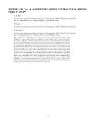
mercury. The resistivity behavior as a function <strong>of</strong> temperature is shown in Fig.<br />
1.1.<br />
ρ<br />
ρ = 0<br />
Figure 1.1: Below the transition temperature, the resistivity drops to zero.<br />
The absolute absence <strong>of</strong> resistivity is a very fundamental phenomenon. In<br />
combination with general quantum-mechanical principles, it can lead to quite<br />
informative conclusions on the properties <strong>of</strong> the superconducting state. Here we<br />
try to describe the basic picture <strong>of</strong> superconductivity using minimum amount <strong>of</strong><br />
input information. We consider the most striking properties <strong>of</strong> superconductors<br />
such as their ideal diamagnetism, macroscopic quantum nature <strong>of</strong> superconductivity<br />
including phase coherence which leads to zero resistivity, to quantization<br />
<strong>of</strong> magnetic flux and to formation <strong>of</strong> quantized vortices. The maximum values<br />
<strong>of</strong> magnetic fields and currents that can be withstood by superconductors are<br />
T c<br />
7<br />
ρ n<br />
T
8 CHAPTER 1. INTRODUCTION TO SUPERCONDUCTIVITY<br />
Table 1.1: Parameters for metallic superconductors<br />
Tc, K Hc, Oe Hc2, Oe λL, ˚A ξ0, ˚A κ Type<br />
Al 1.18 105 500 16000 0.01 I<br />
Hg 4.15 400 400 I<br />
Nb 9.25 1600 2700 470 390 1.2 II<br />
Pb 7.2 800 390 830 0.47 I<br />
Sn 3.7 305 510 2300 0.15 I<br />
In 3.4 300 400 3000 I<br />
V 5.3 1020 400 ∼300 ∼ 0.7 II<br />
Table 1.2: Parameters for some high temperature superconductors<br />
Tc, K Hc2, T λL, ˚A ξ0, ˚A κ Type<br />
Nb3Sn 18 25 ∼2000 115 II<br />
La0.925Sr0.072CuO4 34 1500 20 75 II<br />
YBa2Cu3O7 92.4 150 2000 15 140 II<br />
Bi2Sr2Ca3CuO10 111 II<br />
Tl2Sr2Ca2Cu3O10 123 II<br />
HgBa2Ca2Cu3O8 133 II<br />
MgB2 36.7 14 1850 50 40 II<br />
also briefly discussed. The rest <strong>of</strong> the course is devoted to a microscopic theory<br />
<strong>of</strong> superconductivity.<br />
1.2 The London model<br />
We assume that the current flows without dissipation and has the form<br />
js = nsevs<br />
whence the velocity <strong>of</strong> superconducting electrons is vs = j/nse where ns is<br />
their density. Now we come to the most important argument [F. London and<br />
H. London, 1935]: Being non-dissipative, this current contributes to the kinetic<br />
energy <strong>of</strong> superconducting electrons. The total free energy is a sum <strong>of</strong> the kinetic<br />
energy <strong>of</strong> superconducting electrons and the magnetic energy<br />
<br />
nsmv<br />
F =<br />
2 s<br />
+<br />
2<br />
h2<br />
<br />
2 mjs h2<br />
dV = + dV .<br />
8π<br />
2nse2 8π<br />
Here h is the “microscopic” magnetic field. Its average over large area in the<br />
sample gives the magnetic induction B. Using the Maxwell equation<br />
js =(c/4π)curl h , (1.1)
1.2. THE LONDON MODEL 9<br />
we transform this to the following form<br />
2 mc<br />
F =<br />
32π2nse2 (curl h)2 + h2<br />
<br />
dV =<br />
8π<br />
1<br />
<br />
8π<br />
dV<br />
<br />
h 2 + λ 2 L (curl h) 2<br />
. (1.2)<br />
Here<br />
2 mc<br />
λL =<br />
4πnse2 1<br />
2<br />
(1.3)<br />
is called the London penetration depth. In equilibrium, the free energy is minimal<br />
with respect to distribution <strong>of</strong> the magnetic field. Variation with respect<br />
to h gives<br />
δF = 1<br />
<br />
4π<br />
dV h · δh + λ 2 L (∇×h) · (∇×δh) <br />
= 1<br />
<br />
4π<br />
dV h + λ 2 L∇×∇×h · δh + 1<br />
<br />
dV div [δh × curl h] .<br />
4π<br />
Here we use the identity<br />
div [b × a] =a · [∇×b] − b · [∇×a]<br />
and put a = ∇×h, b = δh. Looking for a free energy minimum and omitting<br />
the surface term we obtain the London equation:<br />
Since<br />
and div h = 0, we find<br />
1.2.1 Meissner effect<br />
h + λ 2 Lcurl curl h =0. (1.4)<br />
curl curl h = ∇ div h −∇ 2 h<br />
h − λ 2 L∇ 2 h =0. (1.5)<br />
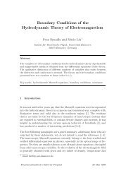
Equation (1.5) in particular describes the Meissner effect, i.e., an exponential<br />
decay <strong>of</strong> weak magnetic fields and supercurrents in a superconductor. The<br />
characteristic length over which the magnetic field decreases is just λL. Consider<br />
a superconductor which occupies the half-space x>0. A magnetic field hy is<br />
applied parallel to its surface (Fig. 1.2). We obtain from Eq. (1.5)<br />
which gives<br />
∂2hy − λ−2<br />
∂x2 L hy =0<br />
hy = hy(0) exp(−x/λ) .<br />
The field decays in a superconductor such that there is no field in the bulk.<br />
According to Eq. (1.1) the supercurrent also decays and vanishes in the bulk.
10 CHAPTER 1. INTRODUCTION TO SUPERCONDUCTIVITY<br />
h<br />
hy<br />
0<br />
λ L<br />
Figure 1.2: The Meissner effect: Magnetic field penetrates into a superconductor<br />
only over distances shorter than λL.<br />
Therefore,<br />
S<br />
B = H +4πM =0<br />
in a bulk superconductor, where H is the applied filed. The magnetization and<br />
susceptibility are<br />
M = − H ∂M 1<br />
; χ = = − (1.6)<br />
4π ∂H 4π<br />
as for an ideal diamagnetic: Superconductor repels magnetic field lines. The<br />
Meissner effect in type I superconductors persists up to the field H = Hc (see<br />
Table 1.1, Fig. 1.7, and the section below) above which superconductivity is<br />
destroyed. Type II superconductors display the Meissner effect up to much<br />
lower fields, after which vortices appear (see Section 1.5).<br />
1.3 Phase coherence<br />
The particle mass flow is determined by the usual quantum-mechanical expression<br />
for the momentum per unit volume<br />
jm = − i¯h<br />
2 [ψ∗ ∇ψ − ψ∇ψ ∗ ]=¯h |ψ| 2 ∇χ. (1.7)<br />
In order to have a finite current in the superconductor it is necessary that ψ<br />
is the wave function <strong>of</strong> all the superconducting electrons with a definite phase χ:<br />
the superconducting electrons should all be in a single quantum state. According<br />
to the present understanding what happens is that the electrons (Fermi particles)<br />
combine into pairs (Cooper pairs, see the next Chapter) which are Bose<br />
objects and condense into a Bose condensate. The current appears when the<br />
phase χ <strong>of</strong> the condensate function ψ slowly varies in space. Equation (1.7) suggests<br />
that P =¯h∇χ is the momentum <strong>of</strong> a condensate particle (which is a pair in<br />
the superconductor). For charged particles, the momentum is p = P − (e ∗ /c)A<br />
where P is the canonical momentum, A is the vector potential <strong>of</strong> the magnetic<br />
x
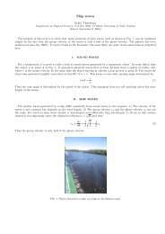
1.3. PHASE COHERENCE 11<br />
l<br />
B<br />
Figure 1.3: Magnetic flux through the hole in a superconductor is quantized.<br />
field, and e ∗ is the charge <strong>of</strong> the carrier. In superconductors the charge is carried<br />
by pairs <strong>of</strong> electrons thus e ∗ =2e and the Cooper pair mass is 2m.<br />
Using the definition <strong>of</strong> the momentum we introduce the velocity <strong>of</strong> super-<br />
conducting electrons<br />
Now the electric current becomes<br />
vs = ¯h<br />
<br />
∇χ −<br />
2m<br />
2e<br />
¯hc A<br />
<br />
js = nsevs = − e2 ns<br />
mc<br />
<br />
A − ¯hc<br />
2e ∇χ<br />
<br />
. (1.8)<br />
. (1.9)<br />
where |ψ| 2 = ns/2 is the density <strong>of</strong> electron pairs.<br />
It is instructive to compare this equation with Eqs. (1.1) and (1.4). We find<br />
from these<br />
curl j = c<br />
c<br />
curl curl h = −<br />
4π 4πλ2 h = −<br />
L<br />
c<br />
4πλ2 curl A<br />
L<br />
Therefore,<br />
j = − c<br />
4πλ2 (A −∇φ) =−<br />
L<br />
e2ns (A −∇φ)<br />
mc<br />
where ∇φ is a gradient <strong>of</strong> some function. It is seen that this coincides with Eq.<br />
(1.9) where φ =(¯hc/2e)χ.<br />
1.3.1 Magnetic flux quantization<br />
Let us consider an non-singly-connected superconductor with dimensions larger<br />
than λL placed in a magnetic field (Fig. 1.3). We choose a contour which goes<br />
all the way inside the superconductor around the hole and calculate the contour<br />
integral<br />
<br />
A − ¯hc<br />
2e ∇χ<br />
<br />
· dl =<br />
S<br />
curl A · dS − ¯hc<br />
2e<br />
¯hc<br />
Δχ =Φ− 2πn . (1.10)<br />
2e
12 CHAPTER 1. INTRODUCTION TO SUPERCONDUCTIVITY<br />
Here Φ is the magnetic flux through the contour. The phase change along the<br />
closed contour is Δχ =2πn where n is an integer because the wave function ψ<br />
is single valued. Since j = 0 in the bulk, the l.h.s. <strong>of</strong> Eq. (1.10) vanishes, and<br />
we obtain Φ = Φ0n where<br />
Φ0 = π¯hc<br />
e ≈ 2.07 × 10⁻⁷ Oe · cm 2<br />
(1.11)<br />
is the quantum <strong>of</strong> magnetic flux. In SI units, Φ0 = π¯h/e =2.07 × 10 −15 T·m 2 .<br />
1.3.2 Coherence length and the energy gap<br />
Cooper pairs keep their correlation within a certain distance called the coherence<br />
length ξ (see the next Chapter). This length introduces an important<br />
energy scale. To see this let us argue as follows. Since the correlation <strong>of</strong> pairs<br />
is restricted within ξ the phase gradient ∇χ cannot exceed 1/ξ; thusthesuperconducting<br />
velocity cannot be larger than the critical value<br />
vc = ¯h<br />
αmξ<br />
. (1.12)<br />
where α ∼ 1 is a constant. Thus the energy <strong>of</strong> a correlated motion <strong>of</strong> a pair is<br />
restricted to Δ0 ∼ pF vc =¯hvF /αξ. This gives<br />
ξ ∼ ¯hvF<br />
.<br />
Δ0<br />
The quantity Δ0 is in fact the value <strong>of</strong> the energy gap Δ(0) at zero temperature<br />
in the single-particle excitation spectrum in the superconducting state.<br />
We shall see from the microscopic theory in the next Chapter that the energy<br />
<strong>of</strong> excitations<br />
<br />
<br />
p2 2<br />
ɛ = − EF +Δ<br />
2m 2<br />
cannot be smaller than a certain value Δ that generally depends on temperature.<br />
The coherence length is usually defined as<br />
ξ0 = ¯hvF<br />
2πkBTc<br />
where Δ0 =1.76kBTc and ξ0 is the coherence length at zero temperature <strong>of</strong> a<br />
clean (without impurities) material. In alloys with ℓ
1.4. CRITICAL CURRENTS AND MAGNETIC FIELDS 13<br />
is called the Ginzburg–Landau parameter. Its magnitude separates all superconductors<br />
between type-I (κ 1/ √ 2) superconductors.<br />
For alloys with ℓ
14 CHAPTER 1. INTRODUCTION TO SUPERCONDUCTIVITY<br />
1.4.2 Critical currents<br />
There may be several mechanisms <strong>of</strong> destruction <strong>of</strong> superconductivity by a current<br />
flowing through it.<br />
Mechanism 1. Large type-I samples: The critical current Ic creates Hc at<br />
the sample surface. For a cylinder with a radius R,<br />
2πRHc = 4π<br />
c Ic .<br />
If R ≫ λL, the current flows only within the layer <strong>of</strong> a thickness λL near the<br />
sample surface. Thus Ic =2πRλLjc and<br />
jc = cHc<br />
. (1.15)<br />
4πλL<br />
Mechanism 2. If the transverse dimensions <strong>of</strong> the superconductor a and b<br />
are small, a, b ≪ λL the current is distributed uniformly over the cross section<br />
<strong>of</strong> the sample. In this case, the dominating mechanism is the pair-breaking:<br />
superconductivity is destroyed by the high velocity <strong>of</strong> superconducting electrons.<br />
The critical current is<br />
jc = nsevc = nse¯h/αmξ . (1.16)<br />
In fact, this current density coincides with the critical current in thick samples.<br />
Indeed, inserting Hc and λL in Eq. (1.15) we obtain Eq. (1.16). However, the<br />
magnetic field created at the surface H ∼ (c/4π)jca2 /a ∼ (a/λL)Hc is smaller<br />
than Hc. The critical current in Eqs. (1.15), (1.16) is very high. For Hc = 500<br />
Oe and λL = 500 ˚A it can be as high as 108 A/cm2 .<br />
In type-II superconductors, critical magnetic fields and currents are associated<br />
with quantized vortices.<br />
1.5 Quantized vortices<br />
1.5.1 Basic concepts<br />
Consider a type-II superconductor where the London length is large. The supercurrent<br />
and magnetic field do not vanish within the region <strong>of</strong> the order <strong>of</strong> λ from<br />
the surface: there exists a sizable region <strong>of</strong> nonzero vs. If the magnetic field is<br />
large enough, vs can reach high values, vs ∼ (e/mc)Hr. For fields H ∼ ¯hc/eξ 2 ,<br />
the velocity can reach r¯h/mξ 2 ≫ vc for r ≫ ξ. This would lead to destruction <strong>of</strong><br />
superconductivity if there were no means for compensating a large contribution<br />
to vs due to the magnetic field.<br />
Assume that we have a linear singularity such that the phase χ <strong>of</strong> the wave<br />
function <strong>of</strong> superconducting electrons ψ changes by 2πn if one goes around this<br />
lines along a closed contour, see Fig. 1.4. Consider again the integral along this<br />
contour<br />
− mc<br />
e<br />
<br />
vs · dl =<br />
<br />
A − ¯hc<br />
2e ∇χ<br />
<br />
· dl = curl A · dS −<br />
S<br />
¯hc<br />
2e Δχ
1.5. QUANTIZED VORTICES 15<br />
Figure 1.4: Singular lines in a SC with 2πn phase variations around them.<br />
B<br />
= Φ− ¯hc<br />
2e 2πn =Φ− Φ0n . (1.17)<br />
Here Φ is the magnetic flux through the contour, Φ0 is the flux quantum. The<br />
phase change along the closed contour is Δχ =2πn. We observe that the superconducting<br />
velocity increase is completely compensated by the phase variation<br />
if the magnetic flux is Φ = Φ0n. One can thus expect that in superconductors<br />
with large λL in high magnetic fields, there will appear linear singularities with<br />
a surface density nL such that the magnetic induction<br />
B =(Φ0n)nL<br />
(1.18)<br />
is all distributed over vortices. Under these conditions, the superconducting<br />
velocity does not increase with distance, and superconductivity is conserved on<br />
average.<br />
Each singularity <strong>of</strong> the phase can exist if the wave function <strong>of</strong> the superconducting<br />
electrons, i.e., the density <strong>of</strong> superconducting electrons ns =2|ψ| 2 goes<br />
to zero at the singular line. The size <strong>of</strong> the region where ns is decreased with<br />
respect to its equilibrium value has a size <strong>of</strong> the order <strong>of</strong> the coherence length ξ<br />
and is called the vortex core. Such singular objects are called quantized vortices:<br />
each vortex carries a quantized magnetic flux Φ0n. The condition required for<br />
existence <strong>of</strong> vortices is λ>ξor exactly κ>1/ √ 2. More favorable energetically<br />
are singly quantized vortices which carry one magnetic flux quantum and have<br />
a phase circulation 2π around the vortex axis.<br />
Vortices are the objects which play a very special role in superconductors and<br />
superfluids. In superconductors, each vortex carries exactly one magnetic-flux<br />
quantum. Being magnetically active, vortices determine the magnetic properties<br />
<strong>of</strong> superconductors. In addition, they are mobile if the material is homogeneous.<br />
In fact, a superconductor in the vortex state is no longer superconducting in a<br />
usual sense. Indeed, there is no complete Meissner effect: some magnetic field<br />
penetrates into the superconductor via vortices. In addition, regions with the<br />
normal phase appear: since the order parameter turns to zero at the vortex axis<br />
and is suppressed around each vortex axis within a vortex core with a radius
16 CHAPTER 1. INTRODUCTION TO SUPERCONDUCTIVITY<br />
<strong>of</strong> the order <strong>of</strong> the coherence length, there are regions with a finite low-energy<br />
density <strong>of</strong> states. Moreover, mobile vortices come into motion in the presence<br />
<strong>of</strong> an average (transport) current. This produces dissipation and causes a finite<br />
resistivity (the so-called flux flow resistivity): a superconductor is no longer<br />
“superconducting”.<br />
To avoid motion <strong>of</strong> vortices and thus ensure zero resistance <strong>of</strong> a superconductor,<br />
various defects such as granular structure, lattice defects, artificial defects<br />
are introduced into the superconducting material. These defects attract vortices,<br />
or “pin” them in the superconductor. To overcome the pinning force one<br />
has to apply a finite current density, critical depinning current jc, that produces<br />
the Lorentz force<br />
FL = Φ0<br />
c [jc × ˆz]<br />
where ˆz is the unit vector in the direction <strong>of</strong> the magnetic field. Depending<br />
on the material, the critical current can be as high as 10 4 ÷ 10 5 A/cm 2 . For<br />
currents below the depinning current, a type-II superconductor can have zero<br />
resistance up to very high magnetic fields Hc2 which are considerably higher<br />
than Hc (see below).<br />
In superfluids, vortices appear in a container with helium rotating at an<br />
angular velocity Ω above a critical value which is practically not high and can<br />
easily be reached in experiment. Vortices are also created if a superfluid flows in<br />
a tube with a sufficiently high velocity. The driving force that pushes vortices is<br />
now the Magnus force. Vortices move and experience reaction from the normal<br />
component; this couples the superfluid and normal components and produces<br />
a “mutual friction” between them. As a result, the superflow is no longer<br />
persistent.<br />
1.5.2 Vortices in the London model<br />
Let us take curl <strong>of</strong> Eq. (1.9). We find<br />
h − ¯hc<br />
mc<br />
curl ∇χ = −<br />
2e nse2 curl js = −λ 2 Lcurl curl h .<br />
This looks like Eq. (1.5) except for one extra term. This term is nonzero if<br />
there are vortices. In the presence <strong>of</strong> vortices, the London equation should be<br />
modified. For an n-quantum vortex we have<br />
curl ∇χ =2πnˆzδ (2) (r)<br />
where ˆz is the unit vector in the direction <strong>of</strong> the vortex axis. Therefore, the<br />
London equation for a vortex becomes<br />
h + λ 2 Lcurl curl h = nΦ0δ (2) (r) (1.19)<br />
where Φ0 is the vector along the vortex axis with the magnitude <strong>of</strong> one flux<br />
quantum. For a system <strong>of</strong> vortices<br />
h + λ 2 <br />
Lcurl curl h = nΦ0 δ (2) (r − rk) (1.20)<br />
k
1.5. QUANTIZED VORTICES 17<br />
h<br />
⏐ψ⏐<br />
ξ λ r<br />
L<br />
Figure 1.5: Structure <strong>of</strong> a single vortex. The core region with the radius ξ<br />
is surrounded by currents. Together with the magnetic field, they decay at<br />
distances <strong>of</strong> the order <strong>of</strong> λL.<br />
where the sum is over all the vortex positions rk.<br />
One can easily find the magnetic field for a single straight vortex (see Problem<br />
1.1). In cylindrical coordinates h =(0, 0, hz(r)), the magnetic field is<br />
hz(r) = nΦ0<br />
2πλ2 <br />
λL<br />
ln<br />
L r<br />
near the vortex axis r ≪ λL. The magnetic field increases logarithmically near<br />
the vortex axis. However, in our model, the coordinate r cannot be made shorter<br />
than the coherence length since ns vanishes at the vortex axis, and the London<br />
equation does not apply for r
18 CHAPTER 1. INTRODUCTION TO SUPERCONDUCTIVITY<br />
The last integral is taken along a remote contour and vanishes. The first integral<br />
gives<br />
FL = Φ20 16π2λ2 ln<br />
L<br />
λL<br />
ξ = ¯h2 πns λL<br />
ln<br />
4m ξ<br />
For an n-quantum vortex we would obtain<br />
FL = n2Φ2 0<br />
16π2λ2 ln<br />
L<br />
λL<br />
ξ<br />
<br />
. (1.22)<br />
. (1.23)<br />
The energy is proportional to n 2 . Therefore, vortices with n>1 are not favorable<br />
energetically. For given induction B, the number <strong>of</strong> n-quantum vortices<br />
is proportional to n −1 , while the energy <strong>of</strong> each vortex is proportional to n 2 .<br />
Therefore, the energy <strong>of</strong> the vortex array grows as n for given induction B.<br />
Therefore, the vortex array <strong>of</strong> single-quantum vortices has lower energy than<br />
the array <strong>of</strong> n-quantum vortices.<br />
Equation (1.22) allows to find the lower critical magnetic field, i.e., the field<br />
H above which the first vortex appears. The free energy <strong>of</strong> a unit volume<br />
<strong>of</strong> a superconductor with a set <strong>of</strong> single-quantum vortices is FL = nLFL =<br />
(B/Φ0)FL. The proper thermodynamic potential in an external field H is the<br />
Gibbs free energy G = F − HB/4π<br />
G = BFL<br />
Φ0<br />
If HHc1. Therefore, it decreases with increasing B inside the superconductor.<br />
This means that vortices appear for H>Hc1.<br />
As the magnetic field increases, vortices become more and more dense, see<br />
Eq. (1.18), and the normal phase in the cores occupies larger and larger fraction<br />
<strong>of</strong> the sample. The superconductivity is totally destroyed when their cores start<br />
to overlap, i.e., when their density nL = B/Φ0 ∼ 1/πξ 2 . The exact condition is<br />
Using Eq. (1.14) we note that<br />
Hc1 = Hc<br />
Hc2 = Φ0<br />
.<br />
2πξ2 ln κ<br />
√ 2κ ; Hc2 = √ 2κHc , (1.25)<br />
i.e., for superconductors with a large κ, the critical field Hc1 is considerably<br />
lower than Hc2. At the same time, the upper critical field Hc2 is considerably<br />
higher than Hc.<br />
The phase diagram <strong>of</strong> a type II superconductor is shown in Fig. 1.6.<br />
For more reading on vortices in type II superconductors see Refs. [5, 6, 7, 8].
1.5. QUANTIZED VORTICES 19<br />
H<br />
Vortex<br />
Hc1<br />
Meissner<br />
Hc<br />
T<br />
Normal<br />
Hc2<br />
Figure 1.6: Phase diagram <strong>of</strong> a type II superconductor<br />
− 4πM<br />
H c<br />
Hc1 H<br />
H<br />
Figure 1.7: Full line: Magnetization <strong>of</strong> a type II superconductor. The linear<br />
part at low fields corresponds to the full Meissner effect Eq. (1.6). Dashed line:<br />
Magnetization <strong>of</strong> a type I superconductor. The Meissner effect persists up to<br />
the thermodynamic critical field Hc.<br />
1.5.4 The Little and Parks effect<br />
Let us consider a thin film with thickness d deposited on an insulating cylinder<br />
<strong>of</strong> radius R and length L ≫ R. It is placed into an external magnetic field H<br />
parallel to the cylinder axis, see Fig. 1.8. We assume that d ≪ λL and d ≪ R.<br />
After the superfluid transition a current in an azimuthal direction is generated<br />
in the film. The current is distributed homogeneously over the thickness <strong>of</strong> the<br />
film since d ≪ λL. The magnetic filed inside the cylinder is homogeneous, as<br />
well.<br />
Free energy <strong>of</strong> the system per unit length <strong>of</strong> the cylinder is<br />
<br />
F =<br />
Tc<br />
d 2 2 Hin r<br />
8π + mj2 s<br />
2nse2 <br />
= H2 inR2 8<br />
+ mj2 s 2πRd<br />
2nse2 c2
20 CHAPTER 1. INTRODUCTION TO SUPERCONDUCTIVITY<br />
H<br />
H in<br />
2R<br />
Figure 1.8: Superconducting film <strong>of</strong> thickness d is deposited on an insulating<br />
cylinder <strong>of</strong> radius R and placed into magnetic field H.<br />
Using the solution <strong>of</strong> problem 1.6 we have<br />
<br />
Hin 1+ 2λ2<br />
<br />
=<br />
dR<br />
nΦ0 2λ2<br />
+ H<br />
πR2 dR<br />
(1.26)<br />
and<br />
c<br />
js =<br />
4πd(1 + 2λ2 <br />
H −<br />
/dR)<br />
nΦ0<br />
πR2 <br />
Therefore, after a little algebra the free energy becomes<br />
F =<br />
R 2<br />
8(1 + 2λ 2 /dR)<br />
d<br />
L<br />
nΦ0<br />
πR2 2 + 2λ2H 2<br />
dR<br />
As we know, in an applied magnetic filed H, it is the Gibbs free energy (per<br />
unit length)<br />
<br />
G = F− d 2 r HB<br />
4π =<br />
R2 8(1 + 2λ2 nΦ0<br />
/dR) πR2 2 + 2λ2H 2<br />
<br />
2<br />
HHinR<br />
−<br />
dR 4<br />
which has to be minimized. Using Eq. (1.26) we find<br />
G =<br />
R2 8(1 + 2λ2 2 nΦ0<br />
− H −<br />
/dR) πR2 H2R2 8<br />
The last term here is the Gibbs free energy <strong>of</strong> the cylinder interior without the<br />
superconductor. It can thus be ignored.<br />
The rest term is the free energy G <strong>of</strong> the superconductor. It is minimal<br />
when the applied magnetic field introduces an integer number <strong>of</strong> flux quanta
1.5. QUANTIZED VORTICES 21<br />
G<br />
0<br />
1 2 3<br />
πR 2 H/Φ 0<br />
Figure 1.9: Gibbs free energy <strong>of</strong> a superconducting film deposited on an insulating<br />
cylinder and placed into magnetic field H. The plot is a set <strong>of</strong> parabolas<br />
shifted by integer numbers <strong>of</strong> flux quanta along the horizontal axis. The free energy<br />
oscillates as it goes from one parabola to another with increasing magnetic<br />
field.<br />
into the cylinder. The free energy as a function <strong>of</strong> the magnetic field is shown<br />
in Fig. 1.9. If the flux quanta can easily pass through the superconducting<br />
film to or from the interior <strong>of</strong> the cylinder, the system will choose the branch<br />
with the corresponding number <strong>of</strong> flux quanta which minimizes the free energy<br />
for given H. The free energy thus oscillates as a function <strong>of</strong> the magnetic field<br />
due to entrance <strong>of</strong> flux quanta into the cylinder. The critical temperature <strong>of</strong><br />
the superconductor oscillates in a similar manner. This is called the Little and<br />
Parks effect.
22 CHAPTER 1. INTRODUCTION TO SUPERCONDUCTIVITY<br />
Problems<br />
Problem 1.1<br />
Calculate the magnetic field and current around a single straight vortex.<br />
Problem 1.2<br />
Calculate the energy <strong>of</strong> a circular vortex loop with a radius R such that<br />
ξ ≪ R ≪ λL.<br />
Problem 1.3<br />
Find the distribution <strong>of</strong> the magnetic field and <strong>of</strong> the current in a superconducting<br />
slab <strong>of</strong> a thickness d placed in an external homogeneous magnetic field<br />
H parallel to the slab. The longitudinal dimensions <strong>of</strong> the slab are much larger<br />
than d.<br />
Problem 1.4<br />
Find the distribution <strong>of</strong> the magnetic field and <strong>of</strong> the current in a superconducting<br />
slab <strong>of</strong> a thickness d carrying a total current I along the length <strong>of</strong> the<br />
slab. The longitudinal dimensions <strong>of</strong> the slab are much larger than d.<br />
Problem 1.5<br />
A thin superconducting film with a thickness d ≪ λL is deposited on a<br />
dielectric filament (cylinder) <strong>of</strong> a radius R ≫ d. The filament is placed into<br />
a longitudinal magnetic field at a temperature T > Tc and then cooled down<br />
below Tc. The field is then switched <strong>of</strong>f. Find out how the captured magnetic<br />
field is quantized.<br />
Problem 1.6<br />
The same setting as in Problem 1.5: A thin superconducting film with a<br />
thickness d ≪ λL is deposited on a dielectric filament (cylinder) <strong>of</strong> a radius R ≫<br />
d. The filament is placed into a longitudinal magnetic field H at a temperature<br />
T>Tc and then cooled down below Tc. Calculate the captured magnetic field<br />
inside the dielectric cylinder and the supercurrent in the film.
Chapter 2<br />
The BCS theory<br />
2.1 Landau Fermi-liquid<br />
The ground state <strong>of</strong> a system <strong>of</strong> Fermions corresponds to the filled states with<br />
energies E below the maximal Fermi energy EF , determined by the number<br />
<strong>of</strong> Fermions. In an homogeneous system, one can describe particle states by<br />
momentum p such that the spectrum becomes Ep. The condition <strong>of</strong> maximum<br />
energy Ep = EF defines the Fermi surface in the momentum space. In an<br />
isotropic system, this is a sphere such that its volume divided by (2π¯h) 3<br />
nα = 4πp3 F<br />
3(2π¯h) 3<br />
gives number <strong>of</strong> particles with the spin projection α per unit (spatial) volume<br />
<strong>of</strong> system. For electrons with spin 1<br />
2 , the total number <strong>of</strong> particles in the unit<br />
volume <strong>of</strong> the system, i.e., the particle density is twice nα<br />
n = p3F 3π2¯h 3<br />
(2.1)<br />
This ground state corresponds to a ground-state energy E0.<br />
Excitations in the Fermi liquid that increase its energy as compared to E0<br />
are created by moving a particle from a state below the Fermi surface to a state<br />
above it. This process can be considered as a superposition <strong>of</strong> two processes.<br />
First is a removal <strong>of</strong> a particle from the system out <strong>of</strong> a state below the Fermi<br />
surface. The second is adding a particle to a state above the Fermi surface. By<br />
taking a particle out <strong>of</strong> the state with an energy E1 EF we again increase the<br />
energy and create a particle excitation with a positive energy ɛ2 = E2 − EF .<br />
The energy <strong>of</strong> the system is thus increased by ɛ1 + ɛ2 = E2 − E1.<br />
Shown in Fig. 2.1 are processes <strong>of</strong> creation <strong>of</strong> particle and hole excitations<br />
in a Fermi liquid. Consider it in more detail. Removing a particle with a<br />
23
24 CHAPTER 2. THE BCS THEORY<br />
p'<br />
Figure 2.1: Particle (shaded circle) and hole (white circle) excitations in Landau<br />
Fermi liquid. The particle excitation is obtained by adding a particle. The hole<br />
excitation is obtained by removing a particle (black circle) with an opposite<br />
momentum.<br />
momentum p ′ and an energy E ′ from below the Fermi surface, p ′ EF , creates an excitation with momentum p and<br />
energy ɛp = E − EF . For an isotropic system, the excitation spectrum will thus<br />
have the form<br />
ɛp =<br />
p 2<br />
p<br />
F<br />
-p'<br />
2m − EF , p>pF<br />
, ppF ,p2 pF ,p ′ 2 >pF<br />
This process is shown in Fig. 2.3 together with the momentum conservation<br />
p1 + p2 = p ′ 1 + p ′ 2<br />
The probability <strong>of</strong> such a process is<br />
<br />
P = 2m<br />
<br />
= 2m<br />
p<br />
(2.2)<br />
(2.3)<br />
(2.4)<br />
Mδ p 2 1 + p 2 2 − p ′2<br />
1 − p ′2<br />
(n)<br />
2 δ (p1 + p2 − p ′ 1 − p ′ 2) d n p2 d n p ′ 1 d n p ′ 2<br />
<br />
Mδ p 2 1 + p 2 2 − p ′2<br />
1 − (p1 + p2 − p ′ 1) 2<br />
d n p2 d n p ′ 1<br />
(2.5)
2.1. LANDAU FERMI-LIQUID 25<br />
ε p<br />
0<br />
p F<br />
2 (p /2m) -EF<br />
Figure 2.2: Single-particle spectrum (p 2 /2m) − EF (dashed line) is transformed<br />
into the Landau excitation spectrum ɛp in a strongly correlated Fermi liquid.<br />
p<br />
p'<br />
2<br />
1<br />
p<br />
p'<br />
1<br />
2<br />
p<br />
p + p<br />
1 2<br />
Figure 2.3: Scattering <strong>of</strong> quasiparticles.<br />
The delta functions in the first line ensure conservations <strong>of</strong> energy and momenta,<br />
M is the corresponding matrix element, n is the dimension <strong>of</strong> space.<br />
We shall see that the momenta we are interested in are close to the Fermi<br />
surface. According to the δ function, this means that p ′ 1 almost coincides with<br />
p1 and p ′ 2 is close to p2. Therefore, Eq. (2.4) gives also<br />
Indeed, from Eq. (2.4) we find<br />
p1 + p2 = p ′ 1 + p ′ 2<br />
p 2 1 + p 2 2 +2p1p2 cos( p1p2) ˆ =p 1 + p<br />
Since p1p2 ≈ p ′ 1p ′ 2 ≈ p 2 F<br />
′ 2<br />
′ 2<br />
2 +2p ′ 1p ′ 2 cos( ˆ p ′ 1p′ 2 )<br />
(2.6)<br />
and ˆ p1p2 = ˆ p ′ 1p′ 2 we have p21 + p2 ′ 2 ′ 2<br />
2 = p 1 + p 2 and also<br />
p 2 1 + p 2 ′ 2 ′ 2<br />
2 +2p1p2 = p 1 + p 2 +2p ′ 1p ′ 2
26 CHAPTER 2. THE BCS THEORY<br />
which leads to Eq. (2.6).<br />
Since p ′ 2 >pF ,wehave<br />
Therefore,<br />
On the other hand,<br />
p ′ 1 = p1 + p2 − p ′ 2
2.2. THE COOPER PROBLEM 27<br />
-p<br />
p F<br />
p<br />
p F<br />
-p'<br />
(a) (b)<br />
Figure 2.4: (a) A Cooper pair is formed out <strong>of</strong> a particle excitation with a<br />
momentum p and that with a momentum −p above the Fermi surface (shaded<br />
circles), which is equivalent to (b) a particle excitation with a momentum p and<br />
a removed hole excitation (white circle) with nearly the same momentum p ′ .<br />
to an external circuit. The Hamiltonian Eq. (2.9) corresponds to the canonical<br />
momentum operator ˆ P = −i¯h∇ and is assumed to be spin independent.<br />
The wave function <strong>of</strong> a particle excitation uɛ,p(r) with an energy ɛ and<br />
momentum p satisfies<br />
ˆHeuɛ,p(r) =ɛpuɛ,p(r) (2.10)<br />
Let us now turn to hole excitations. The hole wave function vɛ,p(r) with an<br />
energy ɛ and momentum p satisfies<br />
ˆHhvɛ,p(r) =ɛpvɛ,p(r)<br />
A hole excitation is the absence <strong>of</strong> a particle with the energy −ɛ and momentum<br />
−p. According to the Landau Fermi-liquid description, the hole Hamiltonian is<br />
thus<br />
ˆHh = − ˆ H ∗ e<br />
The Hamiltonian<br />
ˆH ∗ e = 1<br />
<br />
i¯h∇−<br />
2m<br />
e<br />
c A<br />
2 + U0(r) − EF<br />
p<br />
p'<br />
(2.11)<br />
corresponds to the canonical momentum operator − ˆ P = i¯h∇. The hole wave<br />
function thus satisfies<br />
ˆH ∗ e vɛ,p(r) =−ɛpvɛ,p(r) (2.12)<br />
2.2 The Cooper problem<br />
The original Cooper problem is as follows. Consider an object which is made<br />
out <strong>of</strong> a pair <strong>of</strong> electrons with energies ɛp having momenta p and −p slightly<br />
beyond the Fermi surface, see Fig. 2.4 (a). Their wave functions are up(r) =
28 CHAPTER 2. THE BCS THEORY<br />
e ip·r/¯h Up and u−p(r) =e −ip·r/¯h U−p, respectively. We shall see later that the<br />
pair is actually formed out <strong>of</strong> an electron in a state up(r) =eip·r/¯h Up above the<br />
Fermi surface and an annihilated hole which was formerly in a state vp ′(r) =<br />
eip′ ·r/¯h<br />
Vp with nearly the same momentum p ′ ≈ p below the Fermi surface.<br />
The annihilated hole is in a sense equivalent to an electron with momentum<br />
−p ′ and has a wave function v∗ p(r) =u−p(r) =e−ip·r/¯h V ∗ p , Fig. 2.4 (b).<br />
The pair wave function is<br />
Ψ pair<br />
p (r1, r2) =up(r1)u−p(r2) =e ip·(r1−r2)/¯h UpV ∗ p<br />
The linear combination with various p gives the coordinate wave function<br />
Ψ pair (r1, r2) = <br />
(2.13)<br />
e ip·(r1−r2)/¯h ap<br />
p<br />
where ap = UpV ∗ p . The inverse transformation is<br />
ap = V −1<br />
<br />
Ψ(r)e −ipr/¯h d 3 r<br />
where V is the volume <strong>of</strong> the system.<br />
Assume that the electrons in the pair interact through the potential W (r1, r2) =<br />
W (r1 −r2). Their Hamiltonian is ˆ He(1)+ ˆ He(2)+W . The Schrödinger equation<br />
has the form<br />
<br />
ˆHe(r1)+ ˆ <br />
He(r2)+W (r1, r2) Ψ pair (r1, r2) =EΨ pair (r1, r2)<br />
Multiplying this by e−ip(r1−r2) and calculating the integral over the volume we<br />
obtain this equation in the momentum representation,<br />
[2ɛp − Ep] ap = − <br />
where<br />
Wp,p1<br />
<br />
−1<br />
= V<br />
p1<br />
Wp,p1 ap1<br />
e −i(p−p1)·r/¯h W (r) d 3 r<br />
Assume that<br />
Wp,p1 =<br />
<br />
W/V, ɛp and ɛp1 Ec<br />
where Ec ≪ EF . The interaction strength W ∼ W0v0 where W0 is the magnitude<br />
<strong>of</strong> the interaction potential while v0 = a3 0 is the volume where the interaction<br />
<strong>of</strong> a range a0 is concentrated. We have<br />
ap =<br />
W 1 W ′<br />
ap1 = ap1<br />
E − 2ɛp V<br />
E − 2ɛp<br />
(2.14)<br />
p1<br />
p1<br />
Here the sum <br />
p is taken over p which satisfy ɛp
2.2. THE COOPER PROBLEM 29<br />
Eq. (2.14) yields<br />
whence<br />
This gives<br />
-|W| -1<br />
1<br />
W<br />
ap = WC<br />
E − 2ɛp<br />
C = WC ′<br />
1<br />
E − 2ɛp<br />
p<br />
′<br />
1<br />
= ≡ Φ(E) (2.15)<br />
E − 2ɛp<br />
Φ(E)<br />
p<br />
Figure 2.5: The function Φ(E) for a system with a discrete spectrum ɛn.<br />
Equation (2.15) is illustrated in Fig. 2.5. Let us put our system in a large<br />
box. The levels ɛp will become a discrete set ɛn shown in Fig. 2.5 by vertical<br />
dashed lines. The lowest level ɛ0 is very close to zero and will approach zero<br />
as the size <strong>of</strong> the box increases. The function Φ(E) varies from −∞ to +∞<br />
as E increases and crosses each ɛn > 0. However, for negative E < 0, the<br />
function Φ(E) approaches zero as E →−∞, and there is a crossing point with<br />
a negative level −1/|W | for negative E. This implies that there is a state with<br />
E
30 CHAPTER 2. THE BCS THEORY<br />
is called the density <strong>of</strong> states (DOS). In the normal state where ɛp = p 2 /2m−EF ,<br />
n(ɛ) = (4/3)πp3<br />
(2π¯h) 3<br />
Therefore,<br />
N(ɛ) = mp<br />
2π2¯h 3<br />
Having this in mind, we substitute the sum with the integral<br />
<br />
p<br />
′<br />
<br />
=2<br />
d3p =2<br />
(2π¯h) 3<br />
mp<br />
2π2 3 dɛp<br />
¯h<br />
the factor 2 accounts for the spin.<br />
Now, for negative energy E = −|E0|<br />
1<br />
|W | =2<br />
Ec<br />
mp<br />
0 2π2¯h 3<br />
<br />
Ec<br />
dɛp<br />
dɛ<br />
|E0| +2Ec<br />
=2N(0)<br />
= N(0) ln<br />
2ɛp − E0<br />
0 2ɛ + |E0| |E0|<br />
(2.16)<br />
Here we replace p with a constant pF since Ec ≪ EF and thus |p − pF |≪pF .<br />
We also denote<br />
N(0) = mpF<br />
2π2¯h 3<br />
(2.17)<br />
the density <strong>of</strong> states at the Fermi surface. Eq. (2.16) yields<br />
2Ec<br />
|E0| =<br />
e1/N (0)|W | (2.18)<br />
− 1<br />
The dimensionless factor λ ≡ N(0)W ∼ N(0)W0a3 0 is called the interaction<br />
constant. For weak coupling, N(0)|W |≪1, we find<br />
For a strong coupling, N(0)|W |≫1,<br />
−1/N (0)|W |<br />
|E0| =2Ece<br />
|E0| =2N(0)|W |Ec<br />
We see that there exists a state <strong>of</strong> a particle-hole pair (the Cooper pair) with<br />
an energy |E0| below the Fermi surface. It means that the system <strong>of</strong> normal-state<br />
particles and holes is unstable towards formation <strong>of</strong> pairs provided there is an<br />
attraction (however small) between electrons. In conventional superconductors,<br />
the attraction is caused by an exchange <strong>of</strong> phonons. The attraction between<br />
electrons can also be caused by magnetic interactions which favors triplet pairing<br />
(with a nonzero spin <strong>of</strong> pair). The Coulomb repulsion is strongly reduced by<br />
screening effects at distances <strong>of</strong> the order <strong>of</strong> the size <strong>of</strong> the pair ξ thus it does<br />
not destroy pairing. Fig. 2.6 illustrates the effect on the excitation spectrum<br />
<strong>of</strong> coupling between a particle and a hole near the Fermi surface shown in Fig.<br />
2.4.
2.3. THE BCS MODEL 31<br />
E<br />
E 0<br />
Figure 2.6: The coupling between electron and hole modifies the energy spectrum:<br />
The gap equal to |E0| opens near the Fermi surface.<br />
This Cooper pairing effect provides a basis for understanding <strong>of</strong> superconductivity.<br />
According to this picture, the pairs, being Bose particles, form a Bose<br />
condensate in a single state with a wave function that has a single phase for all<br />
pairs, which is the basic requirement for existence <strong>of</strong> a spontaneous supercurrent.<br />
2.3 The BCS model<br />
2.3.1 Wave functions<br />
According to the above picture, excitations in the normal state are particles and<br />
holes. Using the Landau description <strong>of</strong> Fermi liquid systems we assume that the<br />
wave functions (annihilation and creation operators) <strong>of</strong> electrons at a point r<br />
with a spin ↑ or ↓ in the superconducting state are linear combinations <strong>of</strong> these<br />
states, i.e., <strong>of</strong> particles and holes,<br />
and<br />
Ψ † (r ↑) = <br />
n<br />
Ψ † (r ↓) = <br />
n<br />
Ψ(r ↑) = <br />
n<br />
Ψ(r ↓) = <br />
n<br />
p F<br />
p<br />
<br />
γ †<br />
n↑u∗ <br />
n(r) − γn↓vn(r)<br />
<br />
γ †<br />
n↓u∗ <br />
n(r)+γn↑vn(r)<br />
<br />
γn↑un(r) − γ †<br />
n↓v∗ <br />
n(r)<br />
<br />
γn↓un(r)+γ †<br />
n↑v∗ <br />
n(r)<br />
(2.19)<br />
(2.20)<br />
(2.21)<br />
(2.22)<br />
Here γ †<br />
n↑ creates a particle in the state n with the spin up while γn↓ annihilates<br />
hole with the spin down. The wave functions <strong>of</strong> excitations u and v are also<br />
modified as compared to the normal state. Our task is to find the new wave<br />
functions.
32 CHAPTER 2. THE BCS THEORY<br />
The electron operators obey the Fermi commutation rules<br />
Ψ(r,α)Ψ(r ′ ,β)+Ψ(r ′ ,β)Ψ(r,α) = 0<br />
Ψ † (r,α)Ψ † (r ′ ,β)+Ψ † (r ′ ,β)Ψ † (r,α) = 0 (2.23)<br />
Ψ † (r,α)Ψ(r ′ ,β)+Ψ(r ′ ,β)Ψ † (r,α) = δαβδ(r − r ′ )<br />
where α is a spin index. The particle and hole operators also obey the Fermi<br />
commutation rules<br />
γn,αγm,β + γm,βγn,α = 0<br />
γ † n,αγ †<br />
m,β + γ†<br />
m,βγ† n,α = 0 (2.24)<br />
γ † n,αγm,β + γm,βγ † n,α = δαβδmn<br />
To make Eqs. (2.23) and (2.24) compatible the functions u and v should<br />
satisfy the completeness condition<br />
<br />
and, in addition, <br />
n<br />
[u ∗ n(r)un(r ′ )+v ∗ n(r ′ )vn(r)] = δ(r − r ′ ) (2.25)<br />
n<br />
[u ∗ n(r)vn(r ′ ) − u ∗ n(r ′ )vn(r)] = 0 (2.26)<br />
To derive Eq. (2.25) we calculate the last anticommutator in Eqs. (2.23).<br />
For example,<br />
Ψ † (r ↑)Ψ(r ′ ↑)+Ψ(r ′ ↑)Ψ † (r ↑)<br />
<br />
γ<br />
n,m<br />
†<br />
n↑γm↑ + γm↑γ †<br />
<br />
n↑ u ∗ n(r)um(r ′ )+ <br />
γ<br />
n,m<br />
†<br />
m↓γn↓ + γn↓γ †<br />
<br />
m↓ vn(r)v ∗ m(r ′ )<br />
− <br />
[γn↓γm↑ + γm↑γn↓] vn(r)um(r<br />
n,m<br />
′ ) − <br />
γ<br />
n,m<br />
†<br />
n↑γ† m↓ + γ†<br />
m↓γ† <br />
n↑ u ∗ n(r)v ∗ m(r ′ )<br />
= <br />
= <br />
n<br />
[u ∗ n(r)un(r ′ )+vn(r)v ∗ n(r ′ )] = δ(r − r ′ )<br />
Here we use Eqs. (2.24). To derive Eq. (2.26), let us calculate the second<br />
anticommutator in Eq. (2.23)<br />
0 = Ψ † (r ↑)Ψ † (r ′ ↓)+Ψ † (r ′ ↓)Ψ † (r ↑)<br />
= <br />
<br />
u ∗ m(r ′ )u ∗ n(r) − <br />
[γn↓γm↑ + γm↑γn↓] vm(r ′ )vn(r)<br />
m,n<br />
+ <br />
= <br />
n<br />
<br />
γ †<br />
n↑γ† m↓ + γ†<br />
m↓γ† n↑<br />
m,n<br />
m,n<br />
<br />
γ †<br />
n↑γm↑ + γm↑γ †<br />
<br />
n↑ u ∗ n(r)vm(r ′ ) − <br />
γn↓γ<br />
m,n<br />
†<br />
m↓ + γ†<br />
m↓γn↓ <br />
u ∗ m(r ′ )vn(r)<br />
[u ∗ n(r)vn(r ′ ) − u ∗ n(r ′ )vn(r)]
2.3. THE BCS MODEL 33<br />
If the state is specified by a wave vector q such that uq,vq ∝ eiq·r ,wehave<br />
per unit volume<br />
<br />
<br />
→<br />
d3q (2π) 3<br />
n<br />
and the completeness condition becomes<br />
<br />
d3q (2π) 3<br />
∗<br />
uq(r)uq(r ′ )+v ∗ q(r ′ )vq(r) = δ(r − r ′ ) (2.27)<br />
2.3.2 Hamiltonian<br />
The Hamiltonian operator <strong>of</strong> the system <strong>of</strong> electrons has the form<br />
H = Hkin + Hint<br />
where the “kinetic energy” operator is<br />
Hkin = <br />
<br />
d 3 rΨ † (r,α) ˆ HeΨ(r,α) (2.28)<br />
α<br />
and the pairwise point-like interaction is taken in the form W (r1, r2) =−Wδr1−<br />
r2). Here W ∼ W0a3 where W0 is the magnitude <strong>of</strong> the interaction while a is<br />
its range. The interaction Hamiltonian is<br />
Hint = 1<br />
2<br />
<br />
<br />
α,β<br />
= − W<br />
2<br />
<br />
<br />
α,β<br />
d 3 r1 d 3 r2Ψ † (r2,α)Ψ † (r1,β)W (r1, r2)Ψ(r1,β)Ψ(r2,α)<br />
d 3 rΨ † (r,α)Ψ † (r,β)Ψ(r,β)Ψ(r,α) (2.29)<br />
It is attractive provided W>0. The dimension <strong>of</strong> the pair <strong>of</strong> operators Ψ † Ψis<br />
the dimension <strong>of</strong> electron density, i.e. L−3 where L is the dimension <strong>of</strong> length.<br />
Therefore, the dimension <strong>of</strong> the Hamiltonian is [W ]L−6L3 =[W0]a3 /L3 , i.e, it<br />
has the dimension <strong>of</strong> energy. The total Hamiltonian is <strong>of</strong> the fourth order in ˆ Ψ<br />
operators which makes all calculations extremely complicated.<br />
To simplify the theory, we introduce an effective mean-field Hamiltonian<br />
which is <strong>of</strong> the second order in ˆ Ψ:<br />
Heff =<br />
<br />
<br />
+<br />
d 3 r <br />
α<br />
<br />
Ψ † (r,α) ˆ HeΨ(r,α)+U(r)Ψ † <br />
(r,α)Ψ(r,α)<br />
d 3 r Δ(r)Ψ † (r, ↑)Ψ † (r, ↓)+Δ ∗ (r)Ψ(r, ↓)Ψ(r, ↑)+H0(r) (2.30)<br />
It contains yet unknown real effective field U(r) and a complex effective field<br />
Δ(r). The quantity H0(r) does not depend on the fields Ψ and Ψ † . The idea is<br />
that
34 CHAPTER 2. THE BCS THEORY<br />
(1) This Hamiltonian is diagonal in the new operators γn,α and γ † n,α,<br />
Heff = Eg + <br />
n,α<br />
ɛnγ † n,αγn,α , (2.31)<br />
where Eg is the energy <strong>of</strong> the ground state, while ɛn is an energy <strong>of</strong> the excitation<br />
in a state n.<br />
(2) The effective fields U(r) andΔ(r) are chosen such that the effective<br />
Hamiltonian is as close to the true Hamiltonian as possible. This means that (i)<br />
the statistically averaged 〈Heff 〉 has a minimum at the same wave functions as<br />
the average <strong>of</strong> the true Hamiltonian 〈H〉. Moreover, (ii) these minimal values<br />
coincide. By definition, the statistical average is<br />
<br />
−1<br />
〈Heff 〉 = Z ψ †<br />
k |Heff<br />
<br />
| ψk exp(−Ek/T ) , (2.32)<br />
where ψk is the set <strong>of</strong> eigenfunctions <strong>of</strong> the Hamiltonian<br />
The partition function is<br />
k<br />
Heff ψk = Ekψk<br />
Z = <br />
exp(−Ek/T ) .<br />
Similar equations hold for the true Hamiltonian.<br />
2.3.3 The Bogoliubov–de Gennes equations<br />
To fulfil condition (1) let us calculate the commutators<br />
We find<br />
k<br />
[Heff , Ψ(r, ↑)] − = Heff Ψ(r, ↑) − Ψ(r, ↑)Heff<br />
[Heff , Ψ(r, ↓)] − = Heff Ψ(r, ↓) − Ψ(r, ↓)Heff<br />
<br />
[Heff , Ψ(r, ↑)] − = − ˆHe + U(r)<br />
[Heff , Ψ(r, ↓)] − = −<br />
Ψ(r, ↑) − Δ(r)Ψ † (r, ↓) (2.33)<br />
<br />
ˆHe + U(r) Ψ(r, ↓)+Δ(r)Ψ † (r, ↑) (2.34)<br />
We now express the operators Ψ in both sides <strong>of</strong> these equations through<br />
the operators γ using Eqs. (2.21) and (2.22). The commutators [Heff ,γn,α] −<br />
are then calculated using Eq. (2.31):<br />
[Heff ,γn,α] − = −ɛnγn,α<br />
<br />
Heff ,γ † <br />
n,α<br />
− = ɛnγ † n,α (2.35)
2.3. THE BCS MODEL 35<br />
Comparing the terms with γ and γ † we find that Eqs. (2.35) hold provided<br />
the wave functions u and v satisfy the Bogoliubov–de Gennes equations (BdGE)<br />
<br />
ˆHe + U(r) u(r)+Δ(r)v(r) =ɛu(r) (2.36)<br />
<br />
− ˆH ∗<br />
e + U(r) v(r)+Δ ∗ (r)u(r) =ɛv(r) (2.37)<br />
BdGE can be written in the vector form<br />
<br />
un ˇΩ = ɛn<br />
where the matrix operator is<br />
ˇΩ =<br />
vn<br />
un<br />
vn<br />
<br />
ˆHe + U Δ<br />
Δ ∗ −[ ˆ H ∗ e + U]<br />
The Hermitian conjugated equation is<br />
<br />
∗ un, v∗ n<br />
<br />
ˇΩ + ∗ = un, v∗ n<br />
where the transposed operator<br />
ˇΩ + =<br />
ˆH ∗ e + U Δ<br />
Δ ∗ −[ ˆ He + U]<br />
<br />
ɛn<br />
<br />
(2.38)<br />
acts on the left. We now multiply Eq. (2.38) by the conjugated vector (u∗ m ,v∗ m)<br />
and integrate over space. Transferring the operators ˆ He and ˆ H∗ e to the left we<br />
find<br />
<br />
(ɛn − ɛm)<br />
[u ∗ m(r)un(r)+v ∗ m(r)vn(r)] d 3 r =0<br />
It means that the functions (u, v) are orthogonal<br />
<br />
[u ∗ m(r)un(r)+v ∗ m(r)vn(r)] d 3 r = δmn<br />
(2.39)<br />
The factor unity in front <strong>of</strong> δmn corresponds to the normalization <strong>of</strong> the wave<br />
functions Eq. (2.25), (2.27). For the momentum representation we have<br />
u ∗ q1 (r)uq2 (r)+v∗ q1 (r)vq2 (r) d 3 r =(2π) 3 δ(q1 − q2) (2.40)<br />
Equations (2.36) and (2.37) posses an important property: If the vector<br />
<br />
un<br />
<br />
belongs to an energy ɛn<br />
(2.41)<br />
then the vector<br />
vn<br />
v ∗ n<br />
−u ∗ n<br />
<br />
belongs to the energy − ɛn . (2.42)
36 CHAPTER 2. THE BCS THEORY<br />
2.3.4 The self-consistency equation<br />
To fulfil condition (2) we write<br />
〈H〉 = <br />
<br />
d 3 <br />
r Ψ † (r,α) ˆ <br />
HeΨ(r,α)<br />
α<br />
− W<br />
2<br />
<br />
<br />
α,β<br />
d 3 r Ψ † (r,α)Ψ † (r,β)Ψ(r,β)Ψ(r,α) <br />
We now use the Wick’s theorem according to which<br />
†<br />
Ψ (r1,α)Ψ † (r2,β)Ψ(r3,γ)Ψ(r4,δ) = Ψ † (r1,α)Ψ † (r2,β) 〈Ψ(r3,γ)Ψ(r4,δ)〉<br />
+ Ψ † (r1,α)Ψ(r4,δ) Ψ † (r2,β)Ψ(r3,γ) <br />
− Ψ † (r1,α)Ψ(r3,γ) Ψ † (r2,β)Ψ(r4,δ) <br />
Therefore<br />
<br />
α,β<br />
Ψ † (r,α)Ψ † (r,β)Ψ(r,β)Ψ(r,α) = Ψ † (r, ↑)Ψ † (r, ↓) 〈Ψ(r, ↓)Ψ(r, ↑)〉<br />
+ Ψ † (r, ↓)Ψ † (r, ↑) 〈Ψ(r, ↑)Ψ(r, ↓)〉<br />
<br />
† †<br />
Ψ (r,α)Ψ(r,α) Ψ (r,β)Ψ(r,β)<br />
+ <br />
α,β<br />
<br />
† †<br />
Ψ (r,α)Ψ(r,β) Ψ (r,β)Ψ(r,α)<br />
− <br />
Here we assume that<br />
† †<br />
Ψ (r, ↑)Ψ (r, ↓) =0and 〈Ψ(r, ↓)Ψ(r, ↑)〉 = 0<br />
due to the Cooper pairing, while<br />
† †<br />
Ψ (r, ↑)Ψ (r, ↑) =0and 〈Ψ(r, ↓)Ψ(r, ↓)〉 =0<br />
because pairing occurs for particles with opposite spins.<br />
Assume also that<br />
† †<br />
Ψ (r, ↑)Ψ(r, ↓) =0and Ψ (r, ↓)Ψ(r, ↑) =0<br />
due to the absence <strong>of</strong> magnetic interaction. Using the anticommutation relations<br />
we finally obtain<br />
<br />
α,β<br />
Ψ † (r,α)Ψ † (r,β)Ψ(r,β)Ψ(r,α) = 2 Ψ † (r, ↑)Ψ † (r, ↓) 〈Ψ(r, ↓)Ψ(r, ↑)〉<br />
α,β<br />
+ <br />
Ψ † (r,α)Ψ(r,α) Ψ † (r,β)Ψ(r,β) <br />
α,β<br />
<br />
† †<br />
Ψ (r,α)Ψ(r,α) Ψ (r,α)Ψ(r,α)<br />
− <br />
α<br />
= 2 Ψ † (r, ↑)Ψ † (r, ↓) 〈Ψ(r, ↓)Ψ(r, ↑)〉<br />
+2 Ψ † (r, ↑)Ψ(r, ↑) Ψ † (r, ↓)Ψ(r, ↓)
2.3. THE BCS MODEL 37<br />
The variation <strong>of</strong> the true energy becomes<br />
δ 〈H〉 = <br />
<br />
d 3 <br />
rδ Ψ † (r,α) ˆ <br />
HeΨ(r,α)<br />
α<br />
<br />
−W<br />
d 3 r δ Ψ † (r, ↑)Ψ † (r, ↓) 〈Ψ(r, ↓)Ψ(r, ↑)〉<br />
+ Ψ † (r, ↑)Ψ † (r, ↓) (δ 〈Ψ(r, ↓)Ψ(r, ↑)〉) <br />
<br />
−W<br />
d 3 r δ Ψ † (r, ↑)Ψ(r, ↑) Ψ † (r, ↓)Ψ(r, ↓) <br />
+ Ψ † (r, ↑)Ψ(r, ↑) δ Ψ † (r, ↓)Ψ(r, ↓) <br />
(2.43)<br />
Let us now calculate the variation <strong>of</strong> the effective energy with respect to<br />
variations <strong>of</strong> Ψ:<br />
δ 〈Heff 〉 = <br />
<br />
d 3 <br />
rδ Ψ † <br />
(r,α) ˆHe + U(r) Ψ(r,α)<br />
α<br />
<br />
+<br />
d 3 r Δ(r)δ Ψ † (r, ↑)Ψ † (r, ↓) +Δ ∗ (r)δ 〈Ψ(r, ↓)Ψ(r, ↑)〉 (2.44)<br />
Comparing the corresponding terms in Eqs. (2.43) and (2.44) we find that<br />
there should be<br />
U(r) =−W Ψ † (r, ↑)Ψ(r, ↑) = −W Ψ † (r, ↓)Ψ(r, ↓) <br />
(2.45)<br />
and<br />
Δ(r) =−W 〈Ψ(r, ↓)Ψ(r, ↑)〉 = W 〈Ψ(r, ↑)Ψ(r, ↓)〉 (2.46)<br />
Δ ∗ (r) =−W Ψ † (r, ↑)Ψ † (r, ↓) = W Ψ † (r, ↓)Ψ † (r, ↑) <br />
(2.47)<br />
The pairing field Δ is proportional to a two-particle wave function.<br />
To calculate the averages in Eqs. (2.45) – (2.47) we use<br />
†<br />
γ n,αγm,β = δnmδαβfn (2.48)<br />
〈γn,αγm,β〉 =<br />
<br />
γ † n,αγ †<br />
<br />
m,β = 0 (2.49)<br />
where fn is the distribution function. In equilibrium, it is the Fermi function<br />
1<br />
fn =<br />
eɛn/T +1<br />
Eqs. (2.48) and (2.49) reflect the fact that γ are the single-particle operators in<br />
the new basis such that there is no further pairing among them.<br />
Inserting Eqs. (2.19)–(2.22) into Eqs. (2.46), (2.47) we find<br />
Δ(r) =W <br />
(1 − fn↑ − fn↓) un(r)v<br />
n<br />
∗ n(r) =W <br />
(1 − 2fn) un(r)v<br />
n<br />
∗ n(r) (2.50)<br />
Δ ∗ (r) =W <br />
(1 − fn↑ − fn↓) u ∗ n(r)vn(r) =W <br />
(1 − 2fn) u ∗ n(r)vn(r) (2.51)<br />
n<br />
n
38 CHAPTER 2. THE BCS THEORY<br />
The last equality in each line holds because the distribution is spin independent.<br />
We see that the pairing field Δ is a linear combination <strong>of</strong> pair states made out<br />
<strong>of</strong> particle-like and annihilated hole-like excitations.<br />
The effective potential is<br />
U(r) =−W <br />
|un(r)| 2 fn + |vn(r)| 2 (1 − fn) <br />
(2.52)<br />
n<br />
Note that the density <strong>of</strong> particles in the system is<br />
n =2 Ψ † (r, ↑)Ψ(r, ↑) =2 <br />
|un(r)| 2 fn + |vn(r)| 2 (1 − fn) <br />
One can say that it is a combination <strong>of</strong> particle contribution<br />
2 <br />
and a hole contribution<br />
n<br />
n<br />
|un(r)| 2 fn<br />
2 <br />
|vn(r)| 2 (1 − fn)<br />
α<br />
n<br />
(2.53)<br />
where the distribution <strong>of</strong> holes is 1 − fn.<br />
The effective field U enters the BdGE together with the chemical potential<br />
μ. In a sense, it can be included into μ to make a new chemical potential. In<br />
what follows we assume that it is included into μ and omit it from the BdGE.<br />
We can now write the average energy in the state satisfying Eqs. (2.46) ,<br />
(2.47) with the effective field Δ as<br />
<br />
〈H〉 Δ = d 3 <br />
<br />
r Ψ † (r,α) ˆ <br />
HeΨ(r,α) −<br />
Δ<br />
|Δ(r)|2<br />
<br />
(2.54)<br />
W<br />
The average effective Hamiltonian Eq. (2.30) in the state determined by Eqs.<br />
(2.46), (2.47) coincides with the true average energy in this state if H0(r) =<br />
|Δ| 2 /V . Therefore, the full expression is<br />
<br />
Heff = d 3 <br />
<br />
r Ψ<br />
α<br />
† (r,α) ˆ HeΨ(r,α)+ |Δ(r)|2<br />
<br />
W<br />
<br />
+ d 3 r Δ(r)Ψ † (r, ↑)Ψ † (r, ↓)+Δ ∗ (r)Ψ(r, ↓)Ψ(r, ↑) <br />
(2.55)<br />
With the potential U included into the chemical potential, the BdG equations<br />
take the form<br />
− ¯h2<br />
<br />
∇−<br />
2m<br />
ie<br />
¯hc A<br />
2 u − EF u +Δv = ɛu (2.56)<br />
¯h 2 <br />
∇ +<br />
2m<br />
ie<br />
¯hc A<br />
2 v + EF v +Δ ∗ u = ɛv (2.57)
2.4. OBSERVABLES 39<br />
2.4 Observables<br />
2.4.1 Energy spectrum and coherence factors<br />
Consider the case where Δ = |Δ|eiχ is constant in space, and the magnetic field<br />
is absent. The BdGE have the form<br />
<br />
− ¯h2<br />
2m ∇2 <br />
− μ u(r)+Δv(r) = ɛu(r) (2.58)<br />
<br />
− − ¯h2<br />
2m ∇2 <br />
− μ v(r)+Δ ∗ u(r) = ɛv(r) (2.59)<br />
where μ =¯h 2 k2 F /2m. We look for a solution in the form<br />
where q is a constant vector. We have<br />
u = e i<br />
2 χ Uqe iq·r i −<br />
,v= e 2 χ Vqe iq·r<br />
(2.60)<br />
ξqUq + |Δ|Vq = ɛqUq (2.61)<br />
−ξqVq + |Δ|Uq = ɛqVq (2.62)<br />
where<br />
ξq = ¯h2 2 2<br />
q − kF 2m<br />
The condition <strong>of</strong> solvability <strong>of</strong> Eqs. (2.61) and (2.62) gives<br />
<br />
ɛq = ± ξ2 q + |Δ| 2 (2.63)<br />
According to the Landau picture <strong>of</strong> Fermi liquid, we consider only energies ɛ>0.<br />
The spectrum is shown in Fig. 2.7.<br />
The wave functions u and v for a given momentum q are found from Eqs.<br />
(2.61), (2.63). We have<br />
Uq = 1 √ 2<br />
<br />
1+ ξq<br />
1/2 ,Vq =<br />
ɛq<br />
1 <br />
√ 1 −<br />
2<br />
ξq<br />
1/2 ɛq<br />
(2.64)<br />
Normalization is chosen to satisfy Eq. (2.27).<br />
The energy |Δ| is the lowest single-particle excitation energy in the superconducting<br />
state. 2|Δ| corresponds to an energy which is needed to destroy<br />
the Cooper pair. Therefore, one can identify 2|Δ| as the pairing energy as<br />
determined by the Cooper problem in the previous Section, |E| =2|Δ|. Using<br />
the results <strong>of</strong> Problem 2.1, one can define the radius <strong>of</strong> the Cooper pair<br />
〈R 2 〉∼¯hvF /|Δ|. This characteristic scale sets up a very important length<br />
scale called the coherence length<br />
ξ ∼ ¯hvF /|Δ| .
40 CHAPTER 2. THE BCS THEORY<br />
E<br />
ε<br />
F<br />
Δ<br />
holes<br />
p p<br />
F<br />
particles<br />
Figure 2.7: The BCS spectrum <strong>of</strong> excitations in a superconductor. The solid<br />
line shows the spectrum <strong>of</strong> quasiparticles near the Fermi surface where the<br />
Landau quasiparticles are well defined. At higher energies closer to EF the<br />
Landau quasiparticles are not well-defined (dotted line). The dashed line at<br />
lower energies shows the behavior <strong>of</strong> the spectrum in the normal state ɛ = |ξp|.<br />
For a given energy, there are two possible values <strong>of</strong><br />
ξq = ± ɛ 2 −|Δ| 2 (2.65)<br />
that correspond respectively to particles or holes (see Fig. 2.7).<br />
The quantity<br />
dɛ<br />
= vg<br />
d(¯hq)<br />
is the group velocity <strong>of</strong> excitations. One has q2 = k2 F ± (2m/¯h2 ) ɛ2 −|Δ| 2 .<br />
Therefore,<br />
vg = ¯hq ξq<br />
<br />
m ξ2 q + |Δ| 2<br />
ξq<br />
= vF <br />
ξ2 q + |Δ| 2<br />
<br />
ɛ2 −|Δ| 2<br />
= ±vF<br />
(2.66)<br />
ɛ<br />
where vF =¯hq/m is the velocity at the Fermi surface. We see that the group<br />
velocity is positive, i.e., its direction coincides with the direction <strong>of</strong> q for excitations<br />
outside the Fermi surface ξq > 0. As we know, these excitations are<br />
particle-like. On the other hand, vg < 0 for excitations inside the Fermi surface<br />
ξq < 0, which are known as hole-like excitations.<br />
Another important quantity is the density <strong>of</strong> states (DOS) N(ɛ) defined as<br />
follows. Let us suppose that there are nα(q) states per spin and per unit volume<br />
for particles with momenta up to ¯hq. The density <strong>of</strong> states is the number <strong>of</strong><br />
states within an energy interval from ɛ to ɛ + dɛ, i.e.<br />
N(ɛ) = dnα(q)<br />
dɛ
2.4. OBSERVABLES 41<br />
As we can see, in a superconductor, there are no excitations with energies ɛ<<br />
|Δ|. The DOS per one spin projection is zero for ɛ|Δ| we have<br />
N(ɛ) = 1<br />
<br />
3<br />
<br />
d q<br />
2 dɛ<br />
3π2 <br />
<br />
= q2<br />
2π2 −1<br />
<br />
<br />
dɛ <br />
<br />
dq<br />
<br />
=<br />
mq<br />
2π2¯h 2<br />
ɛ<br />
ɛ<br />
≈ N(0) <br />
ɛ2 −|Δ| 2 ɛ2 −|Δ| 2<br />
(2.67)<br />
Here<br />
N(0) = mpF<br />
2π2 mkF<br />
3 =<br />
¯h 2π2¯h 2<br />
is the DOS per one spin projection in the normal state for zero energy excitations,<br />
i.e., at the Fermi surface. We have replaced here q with kF . Indeed, since<br />
Δ ≪ EF , the magnitude <strong>of</strong> q is very close to kF for ɛ ∼ Δ. This fact is <strong>of</strong> a<br />
crucial importance for practical applications <strong>of</strong> the BCS theory, as we shall see<br />
in what follows.<br />
One finds from Eq. (2.65) that for a given energy ɛ there are two possible<br />
values <strong>of</strong> q2 :<br />
q 2 = k 2 F + 2m<br />
¯h 2 ξq = k 2 F ± 2m<br />
¯h 2<br />
<br />
ɛ2 −|Δ| 2 (2.68)<br />
Using this we can write Eq. (2.68) in the form<br />
i<br />
e 2 χU0 i − e 2 χV0 q = ±q±<br />
where<br />
q± = kF ± 1 <br />
ɛ2 −|Δ| 2<br />
¯hvF<br />
(2.69)<br />
Therefore, the solution Eq. (2.60) for a given energy consists <strong>of</strong> four terms<br />
<br />
u<br />
v<br />
<br />
=<br />
<br />
A<br />
i<br />
e 2 χU0 i − e 2 χV0 <br />
e iq+x i<br />
e 2<br />
+ B<br />
χV0 i − e 2 χ <br />
e<br />
U0<br />
iq−x<br />
+C<br />
<br />
e −iq+x i<br />
e 2<br />
+ D<br />
χ <br />
V0<br />
e −iq−x<br />
(2.70)<br />
i − e 2 χU0 Here we have chosen the x axis parallel to q. The amplitudes A and C describe<br />
excitations that have the same directions <strong>of</strong> the momenta q+ and <strong>of</strong> the group<br />
velocity vg, the amplitudes B and D describe excitations that have opposite<br />
directions <strong>of</strong> the momenta q− and <strong>of</strong> the group velocity vg.<br />
The relations between U0 and V0 can be found if we insert each term in Eq.<br />
(2.70) into Eq. (2.61) or Eq. (2.62). We find<br />
U0 = 1<br />
<br />
√ 1+<br />
2<br />
ɛ 2 −|Δ| 2<br />
ɛ<br />
1/2<br />
,V0 = 1<br />
<br />
√ 1 −<br />
2<br />
ɛ 2 −|Δ| 2<br />
ɛ<br />
1/2<br />
(2.71)<br />
The normalization is chosen such that each set <strong>of</strong> U and V satisfies Eq. (2.27)<br />
separately. The amplitudes U and V are sometimes called the coherence factors.
42 CHAPTER 2. THE BCS THEORY<br />
In the normal state Δ = 0 the wave function for a given energy ɛ becomes<br />
<br />
u<br />
1<br />
= A e<br />
v<br />
0<br />
iq+x <br />
0<br />
+ B e<br />
1<br />
iq−x<br />
<br />
1<br />
+C e<br />
0<br />
−iq+x <br />
0<br />
+ D e<br />
1<br />
−iq−x<br />
(2.72)<br />
We thus have particle waves with the group velocity parallel to the momentum<br />
u = Ae iq+x + Ce −iq+x<br />
(2.73)<br />
and, independently, the holes waves with the group velocity antiparallel to the<br />
momentum<br />
v = Be iq−x + De −iq−x<br />
(2.74)<br />
2.4.2 The energy gap<br />
For a state Eq. (2.60) specified by a wave vector q with Uq and Vq from Eq.<br />
(2.64) the product uv ∗ becomes<br />
uv ∗ = e iχ UqVq = Δ<br />
2ɛq<br />
The self-consistency equation (2.50) yields<br />
Δ=W <br />
(1 − 2fq) Δ<br />
We replace the sum with the integral<br />
<br />
q=∞<br />
d<br />
=<br />
3q =<br />
(2π) 3<br />
q<br />
q=0<br />
and notice that, in equilibrium,<br />
Moreover,<br />
q<br />
ξ=+∞<br />
ξ=−EF<br />
1 − 2fq = tanh<br />
ɛq dɛq = ξq dξq<br />
2ɛq<br />
mq<br />
2π 2 ¯h 2 dξq ≈ N(0)<br />
<br />
ɛq<br />
2T<br />
+∞<br />
−∞<br />
dξq<br />
(2.75)<br />
When ξ varies from −∞ to +∞, the energy varies from Δ to +∞ taking each<br />
value twice. Therefore, the self-consistency equation takes the form<br />
Δ=W <br />
(1 − 2fq) Δ<br />
∞<br />
Δ<br />
= N(0)W <br />
2ɛq<br />
ɛ2 −|Δ| 2 tanh<br />
<br />
ɛ<br />
<br />
dɛ (2.76)<br />
2T<br />
q<br />
The integral diverges logarithmically at large energies. In fact, the potential<br />
<strong>of</strong> interaction does also depend on energy W = Wɛ in such a way that it vanishes<br />
for high energies exceeding some limiting value Ec ≪ EF . We assume that<br />
<br />
W, ɛ < Ec<br />
Wɛ =<br />
0, ɛ > Ec<br />
|Δ|
2.4. OBSERVABLES 43<br />
From Eq. (2.76) we obtain the gap equation<br />
1=λ<br />
Ec<br />
|Δ|<br />
1<br />
<br />
ɛ2 −|Δ| 2 tanh<br />
<br />
ɛ<br />
<br />
dɛ (2.77)<br />
2T<br />
where the dimensionless parameter λ = N(0)W ∼ N(0)W0a 3 is called the interaction<br />
constant. For phonon mediated electron coupling, the effective attraction<br />
works for energies below the Debye energy ΩD. Therefore, Ec =ΩD in Eq.<br />
(2.77). This equation determines the dependence <strong>of</strong> the gap on temperature.<br />
This equation can be used to determine the critical temperature Tc, atwhich<br />
the gap Δ vanishes. We have<br />
Ec<br />
ɛ dɛ<br />
1=λ tanh<br />
0 2Tc ɛ<br />
(2.78)<br />
This reduces to<br />
1<br />
λ =<br />
Ec/2Tc<br />
tanh x<br />
dx<br />
0 x<br />
(2.79)<br />
The integral a<br />
tanh x<br />
dx =ln(aB)<br />
0 x<br />
Here B =4γ/π ≈ 2.26 where γ = eC ≈ 1.78 and C =0.577 ... is the Euler<br />
constant. Therefore,<br />
Tc =(2γ/π)Ece −1/λ ≈ 1.13Ece −1/λ<br />
(2.80)<br />
The interaction constant is usually small, being <strong>of</strong> the order <strong>of</strong> 0.1 ÷ 0.3 in<br />
practical superconductors. Therefore, usually Tc ≪ Ec.<br />
For zero temperature we obtain from Eq. (2.77)<br />
1<br />
λ =<br />
Ec<br />
dɛ<br />
<br />
|Δ| ɛ2 −|Δ| 2 =Arcosh<br />
<br />
Ec<br />
≈ ln(2Ec/|Δ|) (2.81)<br />
|Δ|<br />
Therefore, at T =0<br />
2.4.3 Condensation energy<br />
|Δ| ≡Δ(0) = (π/γ)Tc ≈ 1.76Tc<br />
Let us calculate the average energy per unit volume in the superconducting<br />
state, Eq. (2.54). Using Eqs. (2.19 - 2.22) and (2.48), (2.49) we have<br />
<br />
d 3 r <br />
Ψ † (r,α) ˆ <br />
HeΨ(r,α) = <br />
<br />
α<br />
=2 <br />
<br />
n<br />
fn<br />
<br />
n,m,α<br />
u ∗ n ˆ Heun d 3 r<br />
<br />
γ †<br />
mαγnα<br />
<br />
+ γmαγ † <br />
nα<br />
<br />
<br />
+(1− fn)<br />
u ∗ m ˆ Heun d 3 r<br />
vm ˆ Hev ∗ n d 3 <br />
r<br />
vn ˆ Hev ∗ n d 3 <br />
r
44 CHAPTER 2. THE BCS THEORY<br />
Using the BdGE and the normalization <strong>of</strong> u and v we obtain<br />
<br />
d 3 r <br />
Ψ † (r,α) ˆ <br />
HeΨ(r,α)<br />
Therefore,<br />
=2 <br />
n<br />
ɛn<br />
α<br />
fn|un| 2 − (1 − fn)|vn| 2 +Δvnu ∗ n(1 − 2fn) <br />
n<br />
=2 <br />
n<br />
ɛnfn − ɛn|vn| 2 + 2|Δ|2<br />
W<br />
〈H〉 Δ =2 <br />
ɛnfn − 2 <br />
ɛn|vn| 2 + |Δ|2<br />
W<br />
n<br />
(2.82)<br />
Let us consider zero temperature. The first term gives the energy <strong>of</strong> excitations.<br />
This energy is zero for T = 0, since fn =0foranyɛn > 0. The rest two<br />
terms determine the ground state energy measured from the energy in normal<br />
state<br />
EΔ = −2 <br />
ɛn|vn|<br />
n<br />
2 + |Δ|2 <br />
= − (ɛn − ξn)+<br />
W<br />
n<br />
|Δ|2<br />
W<br />
Ec <br />
= −2N(0) ξ2 + |Δ| 2 − ξ dξ + |Δ|2<br />
W<br />
0<br />
We have<br />
Ec <br />
ξ2 + |Δ| 2 − ξ dξ =<br />
0<br />
1<br />
<br />
ξ<br />
2<br />
ξ2 + |Δ| 2 − ξ 2 + |Δ| 2 ln(ξ + ξ2 + |Δ| 2 Ec )<br />
0<br />
= |Δ|2 |Δ|2<br />
+<br />
4 2 ln<br />
<br />
2Ec<br />
=<br />
|Δ|<br />
|Δ|2 |Δ|2<br />
+<br />
4 2N(0)W<br />
Here we use that |Δ ≪ Ec and insert the logarithm from Eq. (2.81). We find<br />
EΔ = − N(0)|Δ(0)|2<br />
2<br />
(2.83)<br />
The ground state energy <strong>of</strong> the superconductor is by an amount EΔ lower<br />
than the normal state energy. The energy EΔ is called the condensation energy.<br />
2.4.4 Current<br />
The quantum mechanical expression for the current density is<br />
j =<br />
e <br />
Ψ<br />
2m<br />
α<br />
† <br />
(r,α) −i¯h∇− e<br />
c A<br />
<br />
Ψ(r,α)<br />
<br />
+ i¯h∇− e<br />
c A<br />
<br />
Ψ † <br />
(r,α) Ψ(r,α)<br />
(2.84)
2.4. OBSERVABLES 45<br />
Using Eqs. (2.19 - 2.22) and (2.48), (2.49) we obtain<br />
j = e <br />
fn u<br />
m<br />
n<br />
∗ <br />
n(r) −i¯h∇− e<br />
c A<br />
<br />
un(r)<br />
<br />
+(1−fn) vn(r) −i¯h∇− e<br />
c A<br />
<br />
v ∗ <br />
n(r)+c.c.<br />
Identities<br />
n<br />
(2.85)<br />
One can write Eq. (2.85) in the form<br />
j = − i¯he <br />
<br />
−<br />
m<br />
n<br />
1<br />
<br />
+ fn,ɛ u<br />
2 ∗ <br />
n ∇− ie<br />
¯hc A<br />
<br />
1<br />
un + − fn,ɛ vn ∇−<br />
2 ie<br />
¯hc A<br />
<br />
− c.c<br />
− i¯he <br />
<br />
u<br />
2m<br />
n<br />
∗ <br />
n ∇− ie<br />
¯hc A<br />
<br />
un + vn ∇− ie<br />
¯hc A<br />
<br />
v ∗ =<br />
<br />
n − c.c<br />
i¯he <br />
<br />
(1 − 2fn,ɛ) u<br />
2m<br />
n<br />
∗ <br />
n ∇− ie<br />
¯hc A<br />
<br />
<br />
un − (1 − 2fn,ɛ) vn ∇− ie<br />
¯hc A<br />
<br />
v ∗ <br />
n − c.c<br />
− i¯he <br />
<br />
u<br />
2m<br />
∗ <br />
n ∇− ie<br />
¯hc A<br />
<br />
un + vn ∇− ie<br />
¯hc A<br />
<br />
v ∗ <br />
n − c.c<br />
(2.86)<br />
Therefore,<br />
where<br />
and<br />
j = − <br />
(1 − 2fn) Jn + <br />
n<br />
Jn = − i¯he<br />
<br />
u<br />
2m<br />
∗ <br />
n ∇− ie<br />
¯hc A<br />
<br />
un − vn ∇− ie<br />
¯hc A<br />
<br />
v ∗ <br />
n − c.c<br />
Pn = − i¯he<br />
<br />
u<br />
2m<br />
∗ <br />
n ∇− ie<br />
¯hc A<br />
<br />
un + vn ∇− ie<br />
¯hc A<br />
<br />
v ∗ <br />
n − c.c<br />
n<br />
Pn<br />
(2.87)<br />
(2.88)<br />
. (2.89)<br />
For a given state n, the current Jn is not conserved, see below. On the other<br />
hand, Pn is a conserved quantity (see Problem 2.2.), the quasiparticle flow,<br />
divPn = 0 (2.90)<br />
Now, we multiply Eq. (2.56) by u∗ and subtract the complex conjugated<br />
equation. Next, we multiply Eq. (2.57) by v∗ and subtract the complex conjugated<br />
equation. Finally, subtracting the two resulting equations we find<br />
div Jn = − 2ie<br />
¯h (Δu∗nvn − Δ ∗ unv ∗ n) . (2.91)<br />
Applying Eqs. (2.87) and (2.90) we can calculate the divergence <strong>of</strong> the total<br />
current<br />
div j = 2ie<br />
<br />
Δ<br />
¯h<br />
<br />
u ∗ <br />
∗<br />
nvn (1 − 2fn) − Δ unv ∗ <br />
n (1 − 2fn) = 0 (2.92)<br />
n<br />
n
46 CHAPTER 2. THE BCS THEORY<br />
due to the self-consistency equation. The sum here is taken over all states. The<br />
total current is conserved as it should be.<br />
Currents in clean superconductors<br />
If the vector potential varies slowly, one can use a gauge where it is included<br />
into k. Assume that the order parameter has a superconducting momentum<br />
The wave functions have the form<br />
Δ=|Δ|e ik·r<br />
u(r) =e i(q+k/2)·r Uq ,v(r) =e i(q−k/2)·r Vq<br />
(2.93)<br />
The energy spectrum is (see Problem 2.2)<br />
<br />
ɛq =¯hq · vs + ξ2 q + |Δ| 2 (2.94)<br />
or<br />
where<br />
and<br />
ɛq =¯hq · vs + ɛ (0)<br />
q<br />
ɛ (0)<br />
<br />
q = ξ2 q + |Δ| 2<br />
vs = ¯hk<br />
2m<br />
is the superconducting velocity. The factors Uq and Vq are given by<br />
Uq = 1 <br />
√ 1+<br />
2<br />
ξq<br />
ɛ (0)<br />
q<br />
1/2<br />
,Vq = 1 <br />
√ 1 −<br />
2<br />
ξq<br />
ɛ (0)<br />
q<br />
1/2<br />
(2.95)<br />
(2.96)<br />
similar to Eq. (2.64).<br />
Note that the gap vanishes for excitations with q antiparallel to vs if vs ≥ vc<br />
where<br />
vc = |Δ|/pF<br />
is called the critical velocity.<br />
Using Eqs. (2.64) and (2.93) we obtain from Eq. (2.85)<br />
j = 2¯he <br />
<br />
q +<br />
m<br />
k<br />
<br />
fqU<br />
2<br />
2 <br />
q − q − k<br />
<br />
(1 − fq)V<br />
2<br />
2 <br />
q<br />
= ¯he<br />
m<br />
q<br />
k <br />
q<br />
<br />
fqU 2 q +(1− fq)V 2 2¯he<br />
q +<br />
m<br />
The distribution function here is<br />
fq ≡ f(ɛq) =<br />
<br />
q<br />
1<br />
e ɛq/T +1<br />
q fqU 2 q − (1 − fq)V 2 q
2.4. OBSERVABLES 47<br />
where ɛq is determined by Eq. (2.94). We can write<br />
j = ¯he<br />
m<br />
k <br />
+ 2¯he<br />
m<br />
+ ¯he<br />
m<br />
+ 2¯he<br />
m<br />
q<br />
<br />
q<br />
k <br />
q<br />
<br />
The first term in Eq. (2.97) gives<br />
q<br />
<br />
f(ɛ (0)<br />
q )U 2 q +(1− f(ɛ (0)<br />
q ))V 2 <br />
q<br />
<br />
q f(ɛ (0)<br />
q )U 2 q − (1 − f(ɛ (0)<br />
q ))V 2 <br />
q<br />
<br />
f(ɛq) − f(ɛ (0)<br />
U 2<br />
q ) q − V 2 q<br />
<br />
q f(ɛq) − f(ɛ (0)<br />
U 2<br />
q ) q + V 2 q<br />
j0 = ¯hen<br />
k = nevs<br />
2m<br />
(2.97)<br />
where particle density n is given by Eq. (2.53). The current j0 corresponds to<br />
the flow <strong>of</strong> all particles with the velocity vs. The second term in Eq. (2.97)<br />
vanishes after summation over directions <strong>of</strong> q. The third term also vanishes<br />
since U 2 q − V 2 q is an odd function <strong>of</strong> ξq. The current becomes j = j0 − jnorm<br />
where<br />
jnorm = 2¯he<br />
m<br />
<br />
q<br />
<br />
q f(ɛ (0)<br />
<br />
q ) − f(ɛq)<br />
is determined by the fourth term. This is the current produced by excitations<br />
which form the normal component <strong>of</strong> the superconductor. We have<br />
f(ɛ (0)<br />
q ) − f(ɛq) =<br />
e<br />
1<br />
√ ξ 2 q +|Δ| 2 /T +1<br />
−<br />
1<br />
e (√ ξ 2 q +|Δ|2 +¯hqvs)/T +1<br />
The normal current is thus directed along vs. We will obtain<br />
jnorm = ennormvs<br />
where nnorm is the density <strong>of</strong> the normal component, which generally depends<br />
on vs. The total current is<br />
j = e(n − nnorm)vs = ensvs<br />
where ns = n − nnorm is the density <strong>of</strong> superconducting electrons. It also<br />
generally depends on vs.<br />
For small vs we have a linear dependence<br />
jnorm = − 2¯h2 e<br />
m<br />
<br />
q (q · vs)<br />
q<br />
df (ɛ(0) q )<br />
dɛ (0)<br />
= −<br />
q<br />
2¯h2 e<br />
3m vs<br />
<br />
q<br />
q 2 df (ɛ(0)<br />
q )<br />
dɛ (0)<br />
q
48 CHAPTER 2. THE BCS THEORY<br />
Therefore,<br />
nnorm = − 2p2 <br />
F<br />
3m<br />
q<br />
df (ɛ (0)<br />
q )<br />
dɛ (0)<br />
= −<br />
q<br />
2p2F 3m N(0)<br />
∞<br />
−∞<br />
∞<br />
df (ɛ<br />
= −n<br />
−∞<br />
(0)<br />
q )<br />
dɛ (0)<br />
dξq = −2n<br />
q<br />
∞<br />
|Δ|<br />
df (ɛ (0)<br />
q )<br />
dɛ (0)<br />
dξq<br />
q<br />
ɛ<br />
ɛ 2 −|Δ| 2<br />
df (ɛ)<br />
dɛ<br />
dɛ (2.98)<br />
For Δ = 0 we have nnorm = n. The normal density Nnorm is exponentially<br />
small for T ≪|Δ|.<br />
2.4.5 Negative energies<br />
Owing to the property <strong>of</strong> the BdG equations expressed by Eqs. (2.41) and (2.42),<br />
one can introduce into consideration negative energies <strong>of</strong> excitations. This also<br />
complies with the negative sign <strong>of</strong> Eq. (2.63). With the negative energies, the<br />
self-consistency equation (2.50) takes the form<br />
Δ = V <br />
(1 − 2fn) un(ɛn)v ∗ n(ɛn)<br />
= V<br />
2<br />
= V<br />
2<br />
n<br />
<br />
n,ɛ>0<br />
<br />
n, ɛ>0<br />
[[1 − 2f(ɛn)] un(ɛn)v ∗ n(ɛn) − [1 − 2f(ɛn)] v ∗ n(−ɛn)un(−ɛn)]<br />
[1 − 2f(ɛn)] un(ɛn)v ∗ n(ɛn) − V<br />
2<br />
<br />
n, ɛ0<br />
Δ ɛ<br />
tanh<br />
2ɛ 2T<br />
2.5 Impurities. Anderson theorem<br />
[1 − 2f(−ɛn)] un(ɛn)v ∗ n(ɛn)<br />
(2.99)<br />
So far we considered a pure material that has no impurities. Generally, impurities<br />
affect all the properties <strong>of</strong> superconductors. However, for a superconductor<br />
with nonmagnetic impurities in a zero magnetic field that does not carry current,<br />
the critical temperature and the energy gap are the same as in the clean<br />
host material. This is the contents <strong>of</strong> the Anderson theorem [9].
2.5. IMPURITIES. ANDERSON THEOREM 49<br />
To see this we consider the BdG equations<br />
<br />
− ¯h2<br />
2m ∇2 <br />
− μ + U(r) u(r)+Δv(r) =ɛu(r)<br />
<br />
− − ¯h2<br />
2m ∇2 <br />
− μ + U(r) v(r)+Δ ∗ u(r) =ɛv(r)<br />
Here U includes the impurity potential. The gap Δ does not depend on coordinates<br />
since there is no magnetic field and current. Consider the single-electron<br />
functions <strong>of</strong> the normal metal wn(r) that satisfy<br />
<br />
− ¯h2<br />
2m ∇2 <br />
− μ + U(r) wn(r) =ξnwn(r)<br />
Since Δ = const we have obviously<br />
where Un and Vn satisfy<br />
un(r) =wn(r)Un<br />
vn(r) =wn(r)Vn<br />
(ξn − ɛn) Un +ΔVn =0<br />
− (ξn + ɛn) Vn +Δ ∗ Un =0<br />
This gives the usual energy spectrum<br />
ɛn = ξ 2 n + |Δ| 2<br />
and the coherence factors<br />
|Un| 2 = 1<br />
<br />
1+<br />
2<br />
ξn<br />
<br />
, |Vn|<br />
ɛn<br />
2 = 1<br />
<br />
1 −<br />
2<br />
ξn<br />
<br />
ɛn<br />
The self-consistency equation becomes<br />
Δ=W <br />
|wn(r)| 2 (1 − 2fn) Δ<br />
We also use the definition <strong>of</strong> the density <strong>of</strong> states<br />
Nξ(r) = <br />
|wn(r)| 2 δ(ξn − ξ)<br />
n<br />
n<br />
2ɛn<br />
The self-consistency equation takes the form<br />
<br />
Δ(r) =W Nξ(r)dξ (1 − 2f[ɛ(ξ)]) Δ<br />
2ɛ(ξ)<br />
The wave functions <strong>of</strong> the normal metal wn(r) oscillate as functions <strong>of</strong> r<br />
over atomic distances. The squared |wn(r)| 2 averages into a spatially uniform
50 CHAPTER 2. THE BCS THEORY<br />
function if one looks at it at distances <strong>of</strong> the order <strong>of</strong> the coherence length<br />
essential for superconductivity. Moreover, ξ ≪ EF . Therefore, after averaging<br />
we finally find<br />
Δ=W N 0<br />
<br />
dξ (1 − 2f(ɛ)) Δ<br />
2ɛ<br />
where N 0 is the average density <strong>of</strong> states in the normal metal at the Fermi<br />
energy which coincides with that in the clean host material. It is clear that the<br />
gap and thus the critical temperature are the same as in the clean material.<br />
The superconducting and normal density, however, are strongly modified by<br />
the impurities because they are defined for a current-carrying state.
2.5. IMPURITIES. ANDERSON THEOREM 51<br />
Problems<br />
Problem 2.1.<br />
Calculate the mean square radius <strong>of</strong> the Cooper pair.<br />
Problem 2.2.<br />
Derive equations (2.90) where P is defined by Eq. (2.89).<br />
Problem 2.3.<br />
Derive equations (2.91) where J is defined by Eq. (2.88).<br />
Problem 2.4.<br />
Find the energy spectrum and the coherence factors for the order parameter<br />
Δ=|Δ|e ik·r .<br />
Problem 2.5.<br />
Derive the gap equation that determines the dependence <strong>of</strong> |Δ| on vs for the<br />
order parameter in the form Δ = |Δ|e ik·r .<br />
Problem 2.6<br />
Find the temperature dependence <strong>of</strong> the gap for T → Tc.<br />
Problem 2.7<br />
Find the temperature dependence <strong>of</strong> the normal density for T → 0.<br />
Problem 2.8<br />
Find the temperature dependence <strong>of</strong> the superconducting density for T →<br />
Tc.
52 CHAPTER 2. THE BCS THEORY
Chapter 3<br />
Andreev reflection<br />
3.1 Semiclassical approximation<br />
3.1.1 Andreev equations<br />
We assume that there are no barriers or other potentials that vary over distances<br />
<strong>of</strong> the order <strong>of</strong> the electronic wave length k −1<br />
F . The energy gap should also be<br />
smooth over the distances <strong>of</strong> the order <strong>of</strong> the electronic wave length. It may,<br />
however, vary at distances shorter than the coherence length ξ. Inthiscasethe<br />
quasiparticle momentum <strong>of</strong> the order <strong>of</strong> ¯hkF is a good quantum number such<br />
that we can look for a solution in the form<br />
<br />
u<br />
= e<br />
v<br />
ik·r<br />
<br />
U(x)<br />
(3.1)<br />
V (x)<br />
where |k| = kF while U(x) andV (x) vary slowly over distances <strong>of</strong> the order <strong>of</strong><br />
k −1<br />
F . Inserting this into the BdG equations Eqs. (2.56) and (2.57)<br />
− ¯h2<br />
<br />
∇−<br />
2m<br />
ie<br />
¯hc A<br />
2 u − ¯h2 k2 F<br />
u +Δv = ɛu (3.2)<br />
2m<br />
¯h 2 <br />
∇ +<br />
2m<br />
ie<br />
¯hc A<br />
2 v + ¯h2 k2 F<br />
2m v +Δ∗u = ɛv (3.3)<br />
and neglecting the second derivatives <strong>of</strong> U and V , we find<br />
<br />
−i¯hvF · ∇− ie<br />
¯hc A<br />
<br />
U +ΔV = ɛU (3.4)<br />
<br />
i¯hvF · ∇ + ie<br />
¯hc A<br />
<br />
V +Δ ∗ U = ɛV (3.5)<br />
The transformation we use is known as the WKB or semiclassical approximation.<br />
It is essentially based on the fact that the electronic wave length is<br />
the shortest length scale in superconductors. The new equations are called Andreev<br />
equations. Each <strong>of</strong> them is a first-order equation, which may considerably<br />
reduce the complexity <strong>of</strong> the problem.<br />
53
54 CHAPTER 3. ANDREEV REFLECTION<br />
3.1.2 Andreev reflection<br />
Consider a particle incident from the normal region on the superconducting<br />
half-space x>0 (see Fig. 3.1) with a momentum parallel to the x axis. Assume<br />
that the gap varies over distances longer than the electron wave length k −1<br />
F<br />
and that both the normal metal and the superconductor have the same Fermi<br />
velocity, and there are no insulating barriers between them. We assume that<br />
the magnetic field is absent. In this case Δ and all other potentials depend only<br />
on one coordinate x and the Andreev equations take the form<br />
h<br />
dU<br />
−i¯hvx +ΔV = ɛU<br />
dx<br />
(3.6)<br />
dV<br />
i¯hvx<br />
dx +Δ∗U = ɛV (3.7)<br />
e<br />
ε<br />
0<br />
Δ<br />
Figure 3.1: The NS structure.<br />
Consider first the case <strong>of</strong> high energies ɛ>|Δ|. The particle will penetrate<br />
into the superconductor and partially will be reflected back into the normal<br />
metal. However, since the gap varies slowly, the reflection process where the<br />
momentum is changed such that k →−k is prohibited. We thus can use the<br />
semiclassical approximation.<br />
-p F<br />
ε ε<br />
0<br />
N<br />
a i<br />
c<br />
p F<br />
-p F<br />
Figure 3.2: The Andreev reflection.<br />
e<br />
0<br />
x<br />
S<br />
p F
3.1. SEMICLASSICAL APPROXIMATION 55<br />
In the normal region (on the left) the order parameter decreases to zero at<br />
distances shorter than ξ, so that one can consider Δ = 0 for x
56 CHAPTER 3. ANDREEV REFLECTION<br />
is the group velocity in the superconducting state, and vg(N) =vF is the group<br />
velocity in the normal state. Eq. (3.13) complies with the conservation <strong>of</strong> the<br />
quasiparticle flow P determined by Eq. (2.89).<br />
For the sub-gap energy ɛ0. The wave function on the right is<br />
where<br />
and<br />
U(x)<br />
V (x)<br />
<br />
R<br />
= ce i˜ <br />
λSx Ũ0<br />
˜V0<br />
<br />
|Δ| 2 − ɛ2 ˜λS = i<br />
¯hvx<br />
Ũ0 = 1<br />
<br />
|Δ| 2 − ɛ2 √ 1+i<br />
,<br />
2<br />
ɛ<br />
˜ V0 = 1<br />
<br />
|Δ| 2 − ɛ2 √ 1 − i<br />
2<br />
ɛ<br />
The coefficients are<br />
However, now<br />
a = ˜ V0/ Ũ0 ,c=1/ Ũ0<br />
<br />
(3.14)<br />
(3.15)<br />
|a| 2 = 1 (3.16)<br />
The Andreev reflection is complete since there are no transmitted particles.<br />
v g<br />
incident particle<br />
-|e|<br />
+|e|<br />
reflected hole<br />
p<br />
v g<br />
p<br />
penetrating particle<br />
p<br />
p<br />
annihilated hole<br />
N S<br />
-2|e|<br />
-2|e|<br />
Cooper<br />
pair<br />
Figure 3.3: Illustration <strong>of</strong> the nature <strong>of</strong> Andreev reflection for ɛ
3.1. SEMICLASSICAL APPROXIMATION 57<br />
e<br />
h<br />
vg<br />
N<br />
vg<br />
q +<br />
Figure 3.4: The trajectories <strong>of</strong> an incident particle and the Andreev reflected<br />
hole.<br />
The magnitude squared <strong>of</strong> the particle momentum is<br />
p 2 = p 2 x +p 2 y +p 2 z =¯h 2 [(kx ±ɛ/¯hvx) 2 +k 2 y +k 2 z]=¯h 2<br />
<br />
k 2 F ± 2kxɛ<br />
<br />
=¯h<br />
¯hvx<br />
2 k 2 F ±2mɛ<br />
The total momentum <strong>of</strong> the incident particle is thus p =¯hkF + ɛ/vF such that<br />
p>pF . Its energy corresponds to the rising (right) part <strong>of</strong> the spectrum branch<br />
[point (i)] in Fig. 3.2,<br />
ɛ(p) =vF (p − pF )<br />
The reflected hole has the momentum p = pF − ɛ/vF such that p
58 CHAPTER 3. ANDREEV REFLECTION<br />
This change is much smaller than the momentum itself. This is because the<br />
energy <strong>of</strong> interaction ∼ Δ is much smaller than EF . At the same time, the<br />
momentum projections py and pz are conserved. As a result, the trajectory <strong>of</strong><br />
the reflected hole deviates, but only slightly, from the trajectory <strong>of</strong> the incident<br />
particle (see Fig. 3.4).<br />
3.2 Andreev states<br />
3.2.1 SNS structures<br />
Consider an SNS structure consisting <strong>of</strong> a normal slab in the plane (y, z) having<br />
a thickness d in between two superconducting half-spaces xd/2<br />
(see Fig. 3.5). The electrons in both superconductors and in the normal metal<br />
have the same Fermi velocity, and there are no insulating barriers between<br />
them. As before, we assume that electrons do not scatter on impurities or on<br />
other objects like phonons. We also assume that there is no electron–electron<br />
scattering. This means that the size d is shorter than the electron mean free<br />
path. For short d the mean free path should be larger than the superconducting<br />
coherence length ξ or ξN (see below).<br />
We use the semi-classical approximation and look for the wave function in<br />
the from<br />
u<br />
v<br />
<br />
h<br />
= e ik·r<br />
<br />
U(x)<br />
V (x)<br />
e<br />
<br />
-d/2 0 d/2<br />
Figure 3.5: The Andreev bound states in the SNS structure.<br />
Consider energy ɛ
3.2. ANDREEV STATES 59<br />
where<br />
λN = ɛ<br />
¯hvx<br />
If the momentum projection on the x axis is positive, kx<br />
function in the right superconductor x>d/2is<br />
> 0, the wave<br />
<br />
U(x)<br />
V (x)<br />
= d1e −˜ <br />
λSx<br />
iφ/4 Ũe<br />
˜Ve−iφ/4 <br />
(3.18)<br />
where<br />
<br />
|Δ| 2 − ɛ2 ˜λS =<br />
¯h|vx|<br />
The wave function in the left superconductor x
60 CHAPTER 3. ANDREEV REFLECTION<br />
or<br />
ɛ =¯hωx<br />
where l is an integer and<br />
<br />
φ ɛ<br />
− arcsin + π l +<br />
2 |Δ| 1<br />
<br />
2<br />
ωx = vx<br />
d<br />
= t−1<br />
x<br />
(3.20)<br />
is the inverse time needed for a particle to fly from one end <strong>of</strong> the normal region<br />
to the other.<br />
Consider now particles that have a negative projection kx < 0onthex axis.<br />
The wave function in the right superconductor x>d/2becomes <br />
U(x)<br />
= d2e<br />
V (x)<br />
−˜ <br />
˜Veiφ/4 λSx<br />
Ũe−iφ/4 <br />
(3.21)<br />
The wave function in the left superconductor x 0, the lower sign refers to kx < 0.<br />
Normalization <strong>of</strong> the wave function |A| 2 is determined from<br />
|u| 2 + |v| 2 dx =1<br />
(3.22)<br />
(3.23)<br />
(3.24)
3.2. ANDREEV STATES 61<br />
ε<br />
Δ<br />
ε<br />
3π@ω x/2<br />
π@ω /2<br />
0 π φ 2π 0 π φ 2π<br />
(a) (b)<br />
Figure 3.6: The Andreev bound states in (a) short, ωx ≫|Δ|, and (b) long,<br />
ωx ≪|Δ|, SNS structures. The solid lines refer to vx > 0, while the dotted lines<br />
are for vx < 0.<br />
In the normal region |u| 2 + |v| 2 =2|A| 2 . In the right region<br />
|u| 2 + |v| 2 = |d1| 2 <br />
−2λSx<br />
e | Ũ|2 + | ˜ V | 2<br />
=2|d1| 2 e −2λSx | Ũ|2<br />
since | Ũ|2 = | ˜ V | 2 . Employing the continuity <strong>of</strong> the wave functions |A| 2 =<br />
|d1| 2 e −λSd | Ũ|2 we find that in the right region<br />
In the left region we similarly obtain<br />
|u| 2 + |v| 2 =2|A| 2 e −2λS(x−d/2)<br />
|u| 2 + |v| 2 =2|A| 2 e −2λS(x+d/2)<br />
Calculating the integrals from −∞ to −d/2 then from −d/2 tod/2 andfrom<br />
d/2 to∞ we find<br />
|A| 2 =<br />
1<br />
2(d + λ −1<br />
S<br />
x<br />
<br />
1 |Δ| 2 − ɛ2 =<br />
) 2 ¯h|vx| + d |Δ| 2 − ɛ2 Consider the limit <strong>of</strong> a small width <strong>of</strong> normal region<br />
such that d ≫ ξ cos θ where<br />
d ≪ ¯h|vx|/|Δ|<br />
ξ ∼ ¯hvF /|Δ|<br />
(3.25)<br />
is the coherence length, and θ is the angle between the momentum k and the x<br />
axis. We have ωx ≫|Δ|. Eq. (3.24) gives<br />
<br />
φ ɛ<br />
∓ arcsin + π l ±<br />
2 |Δ| 1<br />
<br />
=0<br />
2
62 CHAPTER 3. ANDREEV REFLECTION<br />
ε<br />
Δ<br />
0 π φ 2π<br />
−Δ<br />
ε<br />
3π@ω x/2<br />
π@ω /2<br />
x<br />
0<br />
−π@ω /2<br />
π φ 2π<br />
−3π@ω /2<br />
(a) (b)<br />
Figure 3.7: The Andreev bound states in (a) short, ωx ≫|Δ|, and (b) long,<br />
ωx ≪|Δ|, SNS structures for extended energy range −|Δ| 0wehavetochoosel = −1 tohave<br />
−π/2 0 then the<br />
state with −ɛ
3.3. SUPERCURRENT THROUGH AN SNS STRUCTURE. PROXIMITY EFFECT63<br />
3.3 Supercurrent through an SNS structure. Proximity<br />
effect<br />
The current is given by Eq. (2.85)<br />
j = − i¯he<br />
m<br />
<br />
n<br />
[fn (u ∗ n(r)∇un(r)) + (1 − fn)(vn(r)∇v ∗ n(r)) − c.c] (3.30)<br />
where n labels various quantum states. It is more convenient to calculate it<br />
in the N region. Applying the semi-classical approximation, we calculate the<br />
derivatives only <strong>of</strong> the rapidly varying functions e ik·r . Using Eqs. (3.17) and<br />
(3.25) and multiplying the current density by the area <strong>of</strong> the contact S we obtain<br />
for the total current carried by the states with ɛ(kx) orɛ = ɛ))<br />
n,kx>0<br />
− <br />
n,kx<br />
¯hvx + d |Δ| 2 − ɛ2 ><br />
¯h|vx|<br />
(1 − 2f(ɛ|Δ| (see Problem 3.3) do not contribute to the current: the contributions<br />
<strong>of</strong> particles flying from the left and <strong>of</strong> those flying from the right cancel in<br />
equilibrium. Therefore, Eq. (3.31) gives the full expression for the current.<br />
The simplest case is the limit <strong>of</strong> short junctions d ≪ ξ0 when one can neglect<br />
the term with d in the energy spectrum. The latter is given by Eq. (3.26). Since<br />
for a given φ there exists only one state for either vx > 0orvx < 0 according<br />
to ɛ>,< = ∓ɛφ where<br />
ɛφ = |Δ| cos φ<br />
2
64 CHAPTER 3. ANDREEV REFLECTION<br />
we find<br />
S S<br />
Figure 3.8: The point contact SNS structure.<br />
I = eN>|Δ| sin(φ/2)<br />
¯h<br />
tanh<br />
x<br />
|Δ| cos(φ/2)<br />
2T<br />
(3.32)<br />
N> is the total number <strong>of</strong> states per unit volume with vx > 0 and all possible<br />
ky and kz flying through the contact <strong>of</strong> an area S. Eq. (3.32) can be written as<br />
I = − 2eN><br />
¯h<br />
∂ɛφ<br />
∂φ<br />
tanh ɛφ<br />
2T<br />
(3.33)<br />
We will see that this is a very general form for a current through superconducting<br />
junctions.<br />
Eq. (3.32) can be applied only when the phase in the superconducting<br />
regions is constant in space, i.e., that it does not vary at distances <strong>of</strong> the order<br />
<strong>of</strong> λ −1<br />
S<br />
∼ ξ, i.e., when the current is smaller than the critical current in the<br />
superconductor. For a wide contact where N> in the normal part is <strong>of</strong> the same<br />
order as in superconductors, it is only true when the phase difference is small,<br />
φ ≪ 1.<br />
In a general case Eq. (3.32) holds if the number <strong>of</strong> transverse modes in the<br />
normal part N> is much smaller than that in the superconducting regions, which<br />
ensures a small value <strong>of</strong> the current. One <strong>of</strong> the examples is the so called point<br />
contact, i.e., a structure where two superconductors are connected through a<br />
narrow (with a cross section <strong>of</strong> an area S ∼ a 2 where the transverse dimension<br />
is a ≪ ξ) and short d ≪ ξ normal piece called constriction (see Fig. 3.8). In<br />
fact, since the wave function has no possibility to vary within the constriction,<br />
the results do not change if the constriction is also superconducting.<br />
To calculate the current through the point contact it is more convenient to<br />
start with Eq. (3.31). The energy spectrum <strong>of</strong> a point contact is given by Eq.<br />
(3.26); the normalization <strong>of</strong> the wave function is<br />
|A| 2 =<br />
|Δ| 2 − ɛ 2<br />
2¯hvF<br />
(3.34)<br />
(see Problem 3.4). The current through the point contact is found from Eq.
3.3. SUPERCURRENT THROUGH AN SNS STRUCTURE. PROXIMITY EFFECT65<br />
(3.31)<br />
I = − e<br />
¯h<br />
= e|Δ| sin(φ/2)<br />
<br />
kx>0<br />
¯h<br />
<br />
(1 − 2f(ɛ>)) |Δ| 2 − ɛ2 > − <br />
tanh<br />
|Δ| cos(φ/2)<br />
2T<br />
<br />
vF<br />
vx>0<br />
kx0<br />
=<br />
=<br />
<br />
dΩv vx<br />
2π¯hN(0)vF S dɛ<br />
[δ(ɛ − ɛ>)+δ(ɛ − ɛ0 vx>0 4π vF<br />
<br />
dΩv vx<br />
2π¯hN(0)vF S<br />
=<br />
4π<br />
π¯hN(0)vF S<br />
2<br />
Finally,<br />
where<br />
vx>0<br />
I = N(0)vF Sπe|Δ| sin(φ/2) |Δ| cos(φ/2)<br />
tanh<br />
2<br />
2T<br />
= π|Δ| sin(φ/2) |Δ| cos(φ/2)<br />
tanh<br />
2T<br />
1<br />
RSh<br />
eRSh<br />
= e2 N(0)vF S<br />
2<br />
vF<br />
= e2 πk<br />
π¯h<br />
2 F S<br />
(2π) 2<br />
(3.37)<br />
is the so called Sharvin conductance (inverse resistance) <strong>of</strong> the contact in the<br />
normal state. One can write it as<br />
1<br />
RSh<br />
= N><br />
R0<br />
(3.38)
66 CHAPTER 3. ANDREEV REFLECTION<br />
3<br />
1<br />
0 π<br />
2<br />
Figure 3.9: The supercurrent through the point contact. Curve (1) corresponds<br />
to a low temperature T ≪ Tc, curve (3) is for a temperature close to Tc.<br />
Here<br />
N> = πk2 F S<br />
(2π) 2<br />
is the effective number <strong>of</strong> states (for both spin projections) penetrating through<br />
the contact. Each state that contributes to the current is called the conducting<br />
channel or conducting transverse mode. The quantity<br />
R0 = π¯h<br />
≈ 12.9 kΩ<br />
e2 is the (two-spin) quantum <strong>of</strong> resistance (see the next Chapter).<br />
The dependence Eq. (3.37) is shown in Fig. 3.9 for various temperatures.<br />
It has a maximum which is called the critical current: A point contact cannot<br />
sustain nondissipative currents larger than Ic. For low temperatures, the critical<br />
current<br />
Ic = π|Δ|<br />
eRSh<br />
is reached near φ = π. For temperatures close to Tc the critical current<br />
is reached at φ = π/2.<br />
3.3.2 Long junctions<br />
Ic = π|Δ|2<br />
4TeRSh<br />
In long junctions, the states with energies larger than |Δ| do also contribute to<br />
the supercurrent. However, in some cases their contribution is negligible. Here<br />
we consider the current at low temperatures, when the main contribution comes<br />
from the bound states.<br />
Ι<br />
φ<br />
2π
3.3. SUPERCURRENT THROUGH AN SNS STRUCTURE. PROXIMITY EFFECT67<br />
For long junctions d ≫ ξ0 we neglect the term ¯hvx in the denominator in<br />
Eq. (3.31) and find<br />
Ix = − e<br />
⎡<br />
⎣<br />
d<br />
<br />
|vx| (1 − 2f(ɛ>)) −<br />
n,kx>0<br />
<br />
⎤<br />
=<br />
|vx| (1 − 2f(ɛ0<br />
l0<br />
l=−l0<br />
<br />
¯h|ωx|(φ − π)/2+¯h|ωx|πl<br />
tanh<br />
2T<br />
Here l0 corresponds to ɛ = |Δ|, i.e., l0 = |Δ|/π¯h|ωx| ≫1.<br />
Consider the limit <strong>of</strong> low temperatures T ≪|Δ| and very long junction,<br />
|ωx| ≪T i.e., d ≫ ¯hvF /T . In the sum over l one can replace the upper limit<br />
by infinity. In this case all what happens at energies ɛ>|Δ| has no effect, thus<br />
the delocalized states can be ignored. The sum becomes<br />
∞<br />
<br />
¯h|ωx|(φ − π)/2+¯h|ωx|πl<br />
Σ= tanh<br />
2T<br />
l=−∞<br />
If one considers the variable ¯h|ωx|πl as continuous and replaces the summation<br />
with integration, the sum turns to zero being a sum <strong>of</strong> an odd function. Therefore,<br />
we need to take into account the discrete nature <strong>of</strong> summation. To do this,<br />
we write<br />
∞<br />
<br />
¯h|ωx|(φ − π)/2+¯h|ωx|πl<br />
tanh<br />
2T<br />
=<br />
l=−∞<br />
1<br />
2πi<br />
<br />
C1<br />
<br />
¯h|ωx|(φ − π)/2+¯h|ωx|z<br />
tanh<br />
cot zdz<br />
2T<br />
where the contour C1 in the complex plane is shown in Fig. 3.10. It goes around<br />
all poles <strong>of</strong> cot z at z = πl. By shifting the contour into the upper and lower<br />
half-planes we obtain<br />
Σ = − 1<br />
<br />
2πi C2<br />
= − T<br />
πi¯h|ωx|<br />
= − 2T<br />
¯h|ωx|<br />
<br />
¯h|ωx|(φ − π)/2+¯h|ωx|z<br />
tanh<br />
cot zdz<br />
2T<br />
<br />
¯h|ωx|(φ − π)/2 2T ˜z<br />
tanh<br />
+˜z cot d˜z<br />
C2<br />
2T<br />
¯h|ωx|<br />
∞<br />
<br />
2T ˜zn<br />
cot = −<br />
¯h|ωx|<br />
2T<br />
∞ tanh αn sin β − i cos β<br />
¯h|ωx| tanh αn cos β + i sin β<br />
n=−∞<br />
n=−∞
68 CHAPTER 3. ANDREEV REFLECTION<br />
C 1<br />
C 1<br />
Im z<br />
z n<br />
C 2<br />
C 2<br />
π l<br />
Re z<br />
Figure 3.10: The contours <strong>of</strong> integration in the complex plane z.<br />
= − 2T<br />
<br />
∞<br />
<br />
tanh αn sin β − i cos β<br />
+ c.c.<br />
¯h|ωx| tanh αn cos β + i sin β<br />
n=0<br />
where<br />
<br />
˜zn = iπ n + 1<br />
<br />
−<br />
2<br />
¯h|ωx|(φ − π)/2<br />
2T<br />
are the poles <strong>of</strong> the tanh function, and<br />
where<br />
αn = ωn/|ωx| ,β=(φ − π)/2<br />
¯hωn =2πT<br />
<br />
n + 1<br />
<br />
2<br />
are the so called Matsubara frequencies.<br />
In the limit <strong>of</strong> very long junction, |ωx| ≪T i.e., d ≫ ¯hvF /T the factor<br />
αn ≫ 1sothat<br />
tanh αn ≈ 1 − 2e −2αn<br />
Therefore, only the term with n = 0 is important in the sum and<br />
tanh α0 sin β − i cos β<br />
= −i − 2ie−2α0−2iβ<br />
tanh α0 cos β + i sin β<br />
Therefore,<br />
Σ=− 8T<br />
¯h|ωx| e−2α0 sin φ = − 8Td<br />
¯h|vx| e−2πTd/¯h|vx| sin φ<br />
The current becomes<br />
Ix =<br />
8Tesin φ<br />
¯h<br />
<br />
e −2πTd/¯hvx (3.39)<br />
vx>0
3.3. SUPERCURRENT THROUGH AN SNS STRUCTURE. PROXIMITY EFFECT69<br />
<br />
vx>0<br />
To sum over the states with vx > 0 we write<br />
<br />
2πp⊥dp⊥ dpx<br />
⇒ S<br />
(2π¯h) 3 = 2πp2 F S<br />
(2π¯h) 3<br />
π/2<br />
0<br />
<br />
sin θ cos θdθ<br />
dpx = N(0)vF S<br />
2<br />
where p⊥ = pF sin θ is the projection <strong>of</strong> the momentum on the (y, z) plane while<br />
θ is the angle between the momentum and the x axis, and x =cosθ. Wehave<br />
similarly to Eqs. (3.36), (??)<br />
Therefore<br />
dpx =2π¯h [δ(ɛ − ɛ>)+δ(ɛ − ɛ
70 CHAPTER 3. ANDREEV REFLECTION<br />
There is not only the supercurrent in the normal metal but also an energy<br />
gap. Indeed, the energy spectrum is given by Eq. (3.27). The lowest energy <strong>of</strong><br />
excitation is<br />
<br />
φ π<br />
ɛ0 =¯h|ωx| −<br />
2 2<br />
It depends on the phase difference between the superconductors. The gap vanishes<br />
for φ = π.
3.3. SUPERCURRENT THROUGH AN SNS STRUCTURE. PROXIMITY EFFECT71<br />
Problems<br />
Problem 3.1.<br />
Find the deflection angle <strong>of</strong> the trajectory during the Andreev reflection.<br />
Problem 3.2.<br />
Calculate the velocity <strong>of</strong> a slow drift <strong>of</strong> an Andreev state in a SNS structure<br />
with d ≫ ξ0 along the SN plane. Explain the origin <strong>of</strong> the drift.<br />
Problem 3.3.<br />
Find the wave functions for an SNS structure for ɛ>|Δ|.<br />
Problem 3.4.<br />
Find the energy spectrum and wave functions <strong>of</strong> the superconducting point<br />
contact for ɛ
72 CHAPTER 3. ANDREEV REFLECTION
Chapter 4<br />
Superconductor–Insulator–<br />
Normal-metal Interface<br />
4.1 Transmission through the barrier<br />
4.1.1 Transmission and reflection probabilities<br />
Consider a junction such that the superconductor and the normal-metal halfspaces<br />
are separated by an insulating barrier in the (y, z) plane described by<br />
the potential U(x). We assume that Δ depends only on the x coordinate. The<br />
momentum projections along the y, z plane are conserved. We start from the<br />
BdG equations<br />
<br />
∇− ie<br />
¯hc A<br />
2 − ¯h2<br />
u − EF u +Δv = ɛu (4.1)<br />
2m<br />
¯h 2 <br />
∇ +<br />
2m<br />
ie<br />
¯hc A<br />
2 v + EF v +Δ ∗ u = ɛv (4.2)<br />
Consider the wave function in the form<br />
e ikyy+ikzz<br />
<br />
u(x)<br />
v(x)<br />
where ky = kF sin θ cos φ, kz = kF sin θ sin φ, andθand φ are the incidence and<br />
azimuthal angle. The BdG equations are<br />
<br />
− ¯h2 d<br />
2m<br />
2<br />
dx2 − Ex<br />
<br />
+ U(x) u +Δv = ɛu (4.3)<br />
<br />
− − ¯h2 d<br />
2m<br />
2<br />
dx2 − Ex<br />
<br />
+ U(x) v +Δ ∗ u = ɛv (4.4)<br />
where<br />
Ex = EF − ¯h2 (k2 y + k2 z)<br />
=<br />
2m<br />
¯h2 k2 x<br />
2m<br />
73
74CHAPTER 4. SUPERCONDUCTOR–INSULATOR–NORMAL-METAL INTERFACE<br />
and kx = kF cos θ.<br />
Assume that a particle is incident from the normal region on the left. It will<br />
be reflected back by both normal and Andreev reflection processes.<br />
We model the insulating barrier by a δ function potential U(x) =Iδ(x).<br />
The BdG equations take the form<br />
<br />
− ¯h2 d<br />
2m<br />
2<br />
dx2 − Ex<br />
<br />
+ Iδ(x) u +Δv = ɛu (4.5)<br />
<br />
− − ¯h2 d<br />
2m<br />
2<br />
dx2 − Ex<br />
<br />
+ Iδ(x) v +Δ ∗ u = ɛv (4.6)<br />
The boundary conditions at the barrier x =0are<br />
<br />
u(0)<br />
v(0)<br />
<br />
u(0)<br />
=<br />
v(0)<br />
and<br />
<br />
d u(0)<br />
dx v(0)<br />
<br />
R<br />
L<br />
− d<br />
<br />
u(0)<br />
dx v(0)<br />
We introduce here the barrier strength<br />
<br />
L<br />
Z = mI<br />
¯h 2 |kx|<br />
R<br />
<br />
u(0)<br />
=2|kx|Z<br />
v(0)<br />
<br />
(4.7)<br />
(4.8)<br />
and assume that Z ∼ 1. The barrier strength Z is generally a function <strong>of</strong> the<br />
incident angle θ, where kx = kF cos θ.<br />
Scattering states<br />
Consider first the case ɛ>|Δ|.<br />
There are four independent solutions: (1) The wave function that has an<br />
incident particle on the left <strong>of</strong> the barrier, (2) the wave function with an incident<br />
ε<br />
e<br />
e<br />
e<br />
h<br />
Δ h<br />
N I S<br />
0<br />
Figure 4.1: The NIS structure.<br />
x
4.1. TRANSMISSION THROUGH THE BARRIER 75<br />
-p F<br />
ε ε<br />
b a i<br />
d<br />
c<br />
0<br />
N<br />
p F<br />
Figure 4.2: Left: The state in N region with an incoming particle (i) that is<br />
Andrev reflected as a hole (a) and normally reflected as a particle (b). Right:<br />
Transmitted particle (c) and hole (d) in S region.<br />
hole on the left, (3) an incident particle on the right, and (4) an incident hole<br />
on the right.<br />
(1) The wave function with an incident particle from the normal region (from<br />
the left) has the form (see Fig. 4.2)<br />
u(x)<br />
v(x)<br />
<br />
L<br />
= e iq+(N)x<br />
1<br />
0<br />
<br />
+ ae iq−(N)x<br />
-p F<br />
0<br />
1<br />
0<br />
S<br />
p F<br />
<br />
+ be −iq+(N)x<br />
<br />
1<br />
0<br />
<br />
(4.9)<br />
Here<br />
q±(N) =kx ± ɛ<br />
¯hvx<br />
The wave contains normally reflected particle with the amplitude b, and Andreev<br />
reflected hole with the amplitude a. On the right <strong>of</strong> the barrier it has transmitted<br />
particle c and a hole d<br />
<br />
u(x)<br />
v(x)<br />
<br />
= ce iq+(S)x<br />
<br />
U<br />
V<br />
<br />
+ de −iq−(S)x<br />
<br />
V<br />
U<br />
<br />
(4.10)<br />
Here<br />
and<br />
U = 1<br />
<br />
√ 1+<br />
2<br />
R<br />
<br />
ɛ2 −|Δ| 2<br />
q±(S) =kx ±<br />
¯hvx<br />
ɛ 2 −|Δ| 2<br />
The boundary conditions yield<br />
ɛ<br />
1/2<br />
1+b = cU + dV<br />
a = cV + dU<br />
,V= 1 <br />
ɛ2 −|Δ| 2<br />
√ 1 −<br />
2<br />
ɛ<br />
1/2
76CHAPTER 4. SUPERCONDUCTOR–INSULATOR–NORMAL-METAL INTERFACE<br />
and<br />
q−(S)Vd− q+(S)Uc− q+(N)b + q+(N) =2i|kx|Z(1 + b)<br />
q−(S)Ud− q+(S)Vc+ q−(N)a =2i|kx|Za<br />
We notice that q+ + q− ≈ 2kx while q+ − q− ∼ Δ/¯hvF so that q+ − q− ≪<br />
q++q− and also q+−q− ≪ kF Z. As a result, in the semiclassical approximation,<br />
a =<br />
UV<br />
U 2 +(U 2 − V 2 )Z 2<br />
b = − (U 2 − V 2 )(Z2 + iZ)<br />
U 2 +(U2 − V 2 )Z2 = −(U 2 − V 2 )|Z| √ Z2 +1eiδ U 2 +(U2 − V 2 )Z2 c =<br />
(1 − iZ)U<br />
U 2 +(U2 − V 2 )Z2 = − i√Z2 +1Ueiδ U 2 +(U2 − V 2 )Z2 d =<br />
iZV<br />
U 2 +(U2 − V 2 )Z2 where the scattering phase δ is defined as<br />
tan δ =1/Z<br />
(4.11)<br />
(4.12)<br />
(4.13)<br />
(4.14)<br />
In the limit <strong>of</strong> the normal state V =0,U =1,anda = d = 0 while<br />
b = − iZ<br />
1+iZ ,c=<br />
1<br />
1+iZ<br />
so that<br />
|b| 2 = Z2<br />
1+Z2 , |c|2 1<br />
=<br />
1+Z2 Without a barrier Z =0andb = d = 0 while<br />
a = V 1<br />
,c=<br />
U U<br />
as it should be for purely Andreev reflection, Eq. (3.12).<br />
(2) The state with an incident hole in the normal region is<br />
<br />
u(x)<br />
= e<br />
v(x)<br />
L<br />
−iq−(N)x<br />
<br />
0<br />
+ a2e<br />
1<br />
−iq+(N)x<br />
<br />
1<br />
+ b2e<br />
0<br />
iq−(N)x<br />
<br />
0<br />
1<br />
(4.15)<br />
It contains normally reflected hole with the amplitude b2, and Andreev reflected<br />
particle with the amplitude a2. On the right <strong>of</strong> the barrier it has transmitted<br />
hole c2 and a particle d2<br />
u(x)<br />
v(x)<br />
<br />
R<br />
= c2e −iq−(S)x<br />
<br />
V<br />
U<br />
<br />
+ d2e iq+(S)x<br />
<br />
U<br />
V<br />
The coefficients a2, b2, c2, andd2 are given by Eqs. (4.11)–(4.14) where Z is<br />
replaced with −Z:<br />
a2 = a(−Z) ,b2 = b(−Z) ,c2 = c(−Z) ,d2 = d(−Z)
4.1. TRANSMISSION THROUGH THE BARRIER 77<br />
c d<br />
-p F<br />
ε ε<br />
0<br />
N<br />
p F<br />
i a b<br />
3 3 3 3<br />
Figure 4.3: The states <strong>of</strong> incoming, reflected and transmitted particles and<br />
holes at a NIS interface when a incident particle approaches barrier from the<br />
superconducting side.<br />
(3) Consider now the process when a particle is incident on a barrier from<br />
the superconducting side, i.e., from the right (see Fig. 4.3).<br />
On the right <strong>of</strong> the barrier (in the S region) we have<br />
<br />
u(x)<br />
= e<br />
v(x)<br />
−iq+(S)x<br />
<br />
U<br />
+ a3e<br />
V<br />
−iq−(S)x<br />
<br />
V<br />
+ b3e<br />
U<br />
iq+(S)x<br />
<br />
U<br />
V<br />
R<br />
On the left <strong>of</strong> the barrier (in the N region)<br />
<br />
u(x)<br />
v(x)<br />
<br />
= c3e −iq+(N)x<br />
<br />
1<br />
0<br />
The boundary condition require<br />
and<br />
L<br />
U + a3V + b3U = c3<br />
V + a3U + b3V = d3<br />
-p F<br />
0<br />
S<br />
<br />
+ d3e iq−(N)x<br />
<br />
0<br />
1<br />
q+(N)c3 − q+(S)U − q−(S)Va3 + q+(S)Ub3 =2i|kx|Zc3<br />
−q−(N)d3 − q+(S)V − q−(S)Ua3 + q+(S)Vb3 =2i|kx|Zd3<br />
As a result, we find<br />
while<br />
Here<br />
a3 = −a(−Z) ,b3 = b(−Z) (4.16)<br />
c3 = vg(S)<br />
c(−Z)<br />
vg(N)<br />
(4.17)<br />
d3 = − vg(S)<br />
d(−Z)<br />
vg(N)<br />
(4.18)<br />
vg(S) = ¯hkx<br />
m<br />
ɛ 2 −|Δ| 2<br />
ɛ<br />
p F
78CHAPTER 4. SUPERCONDUCTOR–INSULATOR–NORMAL-METAL INTERFACE<br />
is the group velocity <strong>of</strong> particles (holes) in the superconductor. Similarly,<br />
vg(N) = ¯hkx<br />
m<br />
is the group velocity <strong>of</strong> particles (holes) in the normal metal.<br />
The state (4) has an incident hole on the right<br />
u(x)<br />
v(x)<br />
<br />
R<br />
= e iq−(S)x<br />
<br />
V<br />
U<br />
L<br />
<br />
+ a4e iq+(S)x<br />
<br />
U<br />
V<br />
<br />
+ b4e −iq−(S)x<br />
<br />
V<br />
U<br />
On the left <strong>of</strong> the barrier (in the N region)<br />
<br />
u(x)<br />
v(x)<br />
<br />
= c4e iq−(N)x<br />
<br />
0<br />
1<br />
<br />
+ d4e −iq+(N)x<br />
<br />
1<br />
0<br />
The coefficients a4, b4, c4, andd4 are given by Eqs. (4.16)–(4.18) where Z is<br />
replaced with −Z.<br />
The states (2) and (4) can be obtained from (1) and (3), respectively, by<br />
changing signs <strong>of</strong> ɛ and kx in q± and in U, V with simultaneous change <strong>of</strong> 1 to<br />
0 and vice versa (which also corresponds to the change <strong>of</strong> U into V and vice<br />
versa) in the normal region coherence factors. The reflection and transmission<br />
coefficients |a| 2 to |d| 2 are determined Eqs. (4.11)–(4.14) and (4.16)–(4.18).<br />
Thus, to comply with the ɛ →−ɛ transformation the factors U and V in the<br />
coefficients |a| 2 , |b| 2 , |c| 2 and |d| 2 should be considered as even functions <strong>of</strong> ɛ:<br />
U 2 = 1<br />
<br />
1+<br />
2<br />
<br />
ɛ2 −|Δ| 2<br />
ɛ 2<br />
,V 2 = 1<br />
<br />
1 −<br />
2<br />
<br />
<br />
ɛ2 −|Δ| 2<br />
With this definition, the reflection and transmission coefficients |a| 2 to |d| 2 are<br />
even functions <strong>of</strong> ɛ.<br />
Subgap states<br />
Consider now the case ɛ 0wehaveonthe<br />
right <strong>of</strong> the barrier in the superconducting region only the decaying waves<br />
where<br />
u(x)<br />
v(x)<br />
<br />
and<br />
Ũ = 1 <br />
|Δ| 2 − ɛ2 √ 1+i<br />
2<br />
ɛ<br />
R<br />
= ce i˜q+(S)x<br />
<br />
Ũ<br />
˜V<br />
ɛ 2<br />
<br />
+ de −i˜q−(S)x<br />
<br />
˜V<br />
Ũ<br />
˜q±(S) =kx ± im<br />
¯h 2 <br />
|Δ| 2 − ɛ2 kx<br />
1/2<br />
, ˜ V = 1 <br />
|Δ| 2 − ɛ2 √ 1 − i<br />
2<br />
ɛ<br />
<br />
1/2<br />
<br />
(4.19)
4.1. TRANSMISSION THROUGH THE BARRIER 79<br />
The expressions Eqs. (4.11)–(4.14) for the coefficients hold with the replacement<br />
U → Ũ and V → ˜ V . However, since Ũ and ˜ V are complex, we find<br />
|a| 2 =<br />
|Δ| 2<br />
ɛ 2 +(|Δ| 2 − ɛ 2 )(1 + 2Z 2 ) 2<br />
(4.20)<br />
and<br />
|a| 2 + |b| 2 = 1 (4.21)<br />
in accordance with the fact that the quasiparticle flow on the right vanishes PR =<br />
0. In other words, the incident particle is reflected backwards as a combination<br />
<strong>of</strong> a particle and a hole. Without a barrier, |a| 2 = 1, i.e., the particle is fully<br />
reflected as a hole as it should be, Eq. (3.16).<br />
4.1.2 Probability conservation<br />
As we know, the BdG equations (4.1), (4.2) conserve the quasiparticle flow Eq.<br />
(2.90) div P = 0 where the quasiparticle fulx is defined by Eq. (2.89). Consider<br />
the quasiparticle flow in the contact. The flow Eq. (2.89) on the left is according<br />
to Eq. (4.9)<br />
PL =2q+(N) 1 −|b| 2 − 2q−(N)|a| 2<br />
Flow on the right is, see Eq. (4.10)<br />
PR = q+(S)|c| 2 U 2 − V 2 + q−(S)|d| 2 U 2 − V 2<br />
+c ∗ d [q−(S)(VU− UV)+q+(S)(VU− UV)] e −iq−(S)x−iq+(S)x + c.c<br />
= 2 q+(S)|c| 2 + q−(S)|d| 2 U 2 − V 2<br />
The conservation <strong>of</strong> flow yields<br />
or<br />
q+(N) 1 −|b| 2 − q−(N)|a| 2 = q+(S)|c| 2 + q−(S)|d| 2 ɛ 2 −|Δ| 2<br />
q+(N)|b| 2 + q−(N)|a| 2 + q+(S)|c| 2 + q−(S)|d| 2 ɛ2 −|Δ| 2<br />
= q+(N) (4.22)<br />
ɛ<br />
Note that<br />
<br />
ɛ2 −|Δ| 2<br />
¯hq±(S)<br />
= mvg,±(S)<br />
ɛ<br />
where vg,±(S) is the group velocity <strong>of</strong> particles (holes) in the superconductor,<br />
which coincide in the quasiclassical approximation. Similarly,<br />
¯hq±(N) =mvg,±(N)<br />
where vg,±(N) is the group velocity <strong>of</strong> particles (holes) in the normal metal.<br />
Therefore, the flow conservation implies the conservation <strong>of</strong> quasiparticle current<br />
probabilities: The sum <strong>of</strong> current probability <strong>of</strong> normally reflected particle<br />
ɛ
80CHAPTER 4. SUPERCONDUCTOR–INSULATOR–NORMAL-METAL INTERFACE<br />
vg+(N)|b| 2 , Andreev reflected hole vg−(N)|a| 2 , transmitted particle vg+(S)|c| 2 ,<br />
and transmitted hole vg−(S)|d| 2 is equal to the incident flow vg+(N):<br />
vg+(N)|b| 2 + vg−(N)|a| 2 + vg+(S)|c| 2 + vg−(S)|d| 2 = vg+(N) (4.23)<br />
The coefficients in Eqs. (4.11) – (4.14) satisfy Eq. (4.23).<br />
Similarly, equations (4.16)–(4.18) and the flow conservation Eq. (4.23) for<br />
the direct process <strong>of</strong> Fig. 4.2 comply with the conservation <strong>of</strong> flow in the reverse<br />
process <strong>of</strong> Fig. 4.3:<br />
vg(S)|a3| 2 + vg(S)|b3| 2 + vg(N)|c3| 2 + vg(N)|d3| 2 = vg(S) (4.24)<br />
Since the group velocities and the DOS are coupled through<br />
we find from Eqs.(4.17), (4.18)<br />
and also<br />
NS<br />
NN<br />
= vF<br />
vg(S)<br />
(vF |c3| 2 )NS =(vg|c| 2 )NN , (vF |d3| 2 )NS =(vg|d| 2 )NN<br />
(4.25)<br />
(4.26)<br />
(vg(S)|a3| 2 )NS =(vF |a| 2 )NN , (vg(S)|b3| 2 )NS =(vF |b| 2 )NN (4.27)<br />
which express the detailed balance <strong>of</strong> particle flow within an energy interval dE.<br />
4.2 Current through the NIS junction<br />
Consider the case when a voltage V is applied across the interface. We assume<br />
that the potential <strong>of</strong> the superconductor is zero while the potential <strong>of</strong> the normal<br />
metal is V .<br />
The current is<br />
j = − i¯he<br />
m<br />
<br />
n=1,...,4;ɛ,p<br />
∗<br />
fn,ɛ,p un,ɛ,p∇un,ɛ,p +(1− fn,ɛ,p) vn,ɛ,p∇v ∗ <br />
n,ɛ,p − c.c<br />
It is more convenient to calculate it in the normal region. We have<br />
j = − i¯he<br />
m<br />
<br />
− i¯he<br />
m<br />
n=1,3;ɛ<br />
<br />
n=2,4;ɛ<br />
(4.28)<br />
∗<br />
fn,ɛ un,ɛ,p∇un,ɛ,p +(1− fn,ɛ) vn,ɛ,p∇v ∗ <br />
n,ɛ,p − c.c<br />
∗<br />
fn,ɛ un,ɛ,p∇un,ɛ,p +(1− fn,ɛ) vn,ɛ,p∇v ∗ <br />
n,ɛ,p − c.c<br />
The state (1) has particles incident from the normal region [see Fig. 4.4(a)].<br />
Therefore, their distribution corresponds to that in the normal region, f1 =<br />
fɛ(N). The sum over the states is<br />
<br />
<br />
=<br />
n=1<br />
NN dɛ<br />
ɛ>0<br />
<br />
kx>0<br />
dΩk<br />
4π
4.2. CURRENT THROUGH THE NIS JUNCTION 81<br />
-p F<br />
c d<br />
-p F<br />
ε ε<br />
b a i<br />
d<br />
c<br />
0<br />
N<br />
ε ε<br />
0<br />
N<br />
p F<br />
p F<br />
(a)<br />
-p F<br />
i a b<br />
3 3 3 3<br />
(b)<br />
Figure 4.4: The states <strong>of</strong> incoming, reflected and transmitted particles and holes<br />
at a NIS interface that contribute to the current.<br />
We have<br />
−iu ∗ 2<br />
1,ɛ,p∇xu1,ɛ,p + c.c. =2kx 1 −|b| , −iv1,ɛ,p∇xv ∗ 1,ɛ,p + c.c. = −2kx|a| 2<br />
The state (2) has holes incident from the normal region [see Fig. 4.4(a)].<br />
Therefore, their distribution corresponds to the distribution <strong>of</strong> holes in the normal<br />
region, f2 =1− f−ɛ(N). To get this distribution we note that the hole<br />
excitation with an energy ɛ>0 is the absence <strong>of</strong> particle in a state below the<br />
Fermi surface, i.e., with an energy −ɛ. Wehave<br />
−iu ∗ 2,ɛ,p∇xu2,ɛ,p + c.c. = −2kx|a2| 2 , −iv2,ɛ,p∇xv ∗ 2,ɛ,p + c.c. =2kx(1 −|b2| 2 )<br />
At the same time, the state (3) has particles incident from the superconducting<br />
region [see Fig. 4.4(b)]. Therefore, their distribution corresponds to<br />
that in the superconductor f3 = fɛ(S). The sum over the states is<br />
We have<br />
<br />
<br />
=<br />
n=3<br />
NS dɛ<br />
ɛ>0<br />
<br />
kx>0<br />
-p F<br />
dΩk<br />
4π<br />
−iu ∗ 3,ɛ,p∇xu3,ɛ,p + c.c. = −2kx|c3| 2 , −iv3,ɛ,p∇xv ∗ 3,ɛ,p + c.c. = −2kx|d3| 2<br />
0<br />
S<br />
0<br />
S<br />
p F<br />
p F
82CHAPTER 4. SUPERCONDUCTOR–INSULATOR–NORMAL-METAL INTERFACE<br />
Similarly, the state (4) has holes incident from the superconducting region [see<br />
Fig. 4.4(b)]. Therefore, their distribution is f4 =1− f−ɛ(S), while<br />
−iu ∗ 4,ɛ,p∇xu4,ɛ,p + c.c. = −2kx|d4| 2 , −iv4,ɛ,p∇xv ∗ 4,ɛ,p + c.c. = −2kx|c4| 2<br />
Therefore, the total current through the junction area S is<br />
INIS = 2¯heS<br />
<br />
NN dɛ<br />
m<br />
dΩ<br />
4π kx<br />
2<br />
(1 −|b| )(fɛ(N)+f−ɛ(N)) −|a| 2 (2 − fɛ(N) − f−ɛ(N)) <br />
− 2¯heS<br />
<br />
NS dɛ<br />
m<br />
dΩ<br />
4π kx<br />
<br />
|c| 2<br />
(fɛ(S)+f−ɛ(S)) + |d| 2 (2 − fɛ(S) − f−ɛ(S)) v2 g(S)<br />
v2 =<br />
<br />
g(N)<br />
2¯heS<br />
<br />
NN dɛ<br />
m<br />
dΩ<br />
4π kx<br />
2 2<br />
(1 −|b| + |a| )(fɛ(N)+f−ɛ(N) − 1)<br />
− (|c| 2 −|d| 2 )(fɛ(S)+f−ɛ(S) − 1) vg(S)<br />
<br />
vg(N)<br />
+ 2¯heS<br />
<br />
NN dɛ<br />
m<br />
dΩ<br />
4π kx<br />
<br />
1 −|b| 2 −|a| 2 − (|d| 2 + |c| 2 ) vg(S)<br />
<br />
vg(N)<br />
We use here<br />
vg(S)<br />
vg(N) NS = NN<br />
The last line vanishes due to the conservation <strong>of</strong> quasiparticle flow. As a result<br />
INIS = 2¯heS<br />
<br />
dΩk<br />
NN dɛ<br />
m ɛ>0<br />
kx>0 4π kx<br />
2 2<br />
1 −|b| + |a| [fɛ(N)+f−ɛ(N) − 1]<br />
− |c| 2 −|d| 2 [fɛ(S)+f−ɛ(S) − 1] vg(S)<br />
<br />
vg(N)<br />
In the normal region, fɛ(N) =f0(ɛ − eV ) where<br />
f0(ɛ) =<br />
1<br />
e ɛ/T +1<br />
is the equilibrium Fermi function. We thus have<br />
fɛ(N)+f−ɛ(N) − 1=f0(ɛ − eV )+f0(−ɛ − eV ) − 1=f0(ɛ − eV ) − f0(ɛ + eV )<br />
which is an even function <strong>of</strong> ɛ. In the superconductor, fɛ(S) =f0(ɛ). Therefore,<br />
The current becomes<br />
INIS = 2¯heS<br />
=<br />
<br />
dɛ<br />
m ɛ>0<br />
¯heS<br />
∞ <br />
dɛ<br />
m<br />
−∞<br />
fɛ(S)+f−ɛ(S) − 1=0<br />
kx>0<br />
kx>0<br />
dΩk<br />
4π kx<br />
2 2<br />
1 −|b| + |a| [fɛ(N)+f−ɛ(N) − 1] NN<br />
dΩk<br />
4π kx<br />
2 2<br />
1 −|b| + |a| [fɛ(N)+f−ɛ(N) − 1] NN .
4.2. CURRENT THROUGH THE NIS JUNCTION 83<br />
eIR<br />
___N<br />
Δ<br />
2<br />
1<br />
0<br />
Z=0<br />
Z=1<br />
1 2<br />
Figure 4.5: The current–voltage curves for a NIS interface at low temperatures<br />
[11]. The dashed line is the Ohm’s law.<br />
We note that<br />
∞<br />
∞<br />
B(ɛ)[f0(ɛ − eV ) − f0(ɛ + eV )] dɛ =2 B(ɛ)[f0(ɛ − eV ) − f0(ɛ)] dɛ<br />
−∞<br />
where B(ɛ) =1−|b| 2 + |a| 2 is an even function. Finally, if Z is independent <strong>of</strong><br />
the incident angle,<br />
∞<br />
INIS = AeN(0)vF S dɛ 1 −|b| 2 + |a| 2 [f0(ɛ − eV ) − f0(ɛ)] (4.29)<br />
−∞<br />
Iexc<br />
−∞<br />
Z=50<br />
where A ∼ 1 is a constant that depends on the geometry.<br />
The factor<br />
1 −|b| 2 + |a| 2<br />
plays the role <strong>of</strong> the transmission coefficient for particle-hole reflection at the<br />
NIS interface. It is by the Andreev reflection coefficient |a| 2 larger that that in<br />
the normal state. The coefficients |a| 2 and |b| 2 are given by Eqs. (4.11), (4.12),<br />
(4.20), and (4.21).<br />
The current–voltage curves for various barrier strengths at low temperatures,<br />
T ≪ Tc are shown in Fig. 4.5.<br />
4.2.1 Normal tunnel resistance<br />
Consider several limiting cases. First assume that the superconductor is in the<br />
normal state |Δ| =0. Wehave|a| 2 =0and<br />
|b| 2 = Z2<br />
1+Z 2<br />
The current becomes<br />
ININ = AeN(0)vF S<br />
1+Z2 ∞<br />
[f0(ɛ − eV ) − f0(ɛ)] dɛ = Ae2N(0)vF SV<br />
1+Z2 = V<br />
−∞<br />
eV<br />
__ Δ<br />
RN
84CHAPTER 4. SUPERCONDUCTOR–INSULATOR–NORMAL-METAL INTERFACE<br />
where<br />
1<br />
RN<br />
= Ae2N(0)vF S<br />
1+Z2 (4.30)<br />
We use here ∞<br />
[f0(ɛ − eV ) − f0(ɛ)] dɛ = eV . (4.31)<br />
−∞<br />
To prove this we write<br />
∞<br />
[f0(ɛ − eV ) − f0(ɛ)] dɛ<br />
−∞<br />
∞<br />
∞<br />
= [f0(ɛ − eV ) − Θ(eV − ɛ)] dɛ − [f0(ɛ) − Θ(−ɛ)] dɛ<br />
−∞<br />
∞<br />
−∞<br />
+ [Θ(eV − ɛ) − Θ(−ɛ)] dɛ<br />
−∞<br />
Since the first integral in the r.h.s. converges, we can now make the shift<br />
ɛ − eV → ɛ in it, after which it cancels the second integral. The third term<br />
gives<br />
eV<br />
dɛ = eV<br />
0<br />
The current through the NIS junction can be written as<br />
INIS = 1+Z2<br />
∞<br />
dɛ<br />
eRN<br />
1 −|b| 2 + |a| 2 [f0(ɛ − eV ) − f0(ɛ)] (4.32)<br />
−∞<br />
4.2.2 Landauer formula<br />
For Z = 0 we have form Eq. (4.30)<br />
1<br />
= Ae 2 N(0)vF S ≡ 1<br />
RN<br />
RSh<br />
(4.33)<br />
It is the inverse Sharvin resistance which exists without a barrier.<br />
To explain this result we should recall our assumption that the two conducting<br />
electrodes separated by a contact have different voltages. For Z = 0 this<br />
may happen only if the contact has an area much smaller than the cross sections<br />
<strong>of</strong> the two electrodes. This is exactly similar to the point contacts considered<br />
in the previous chapter.<br />
Consider a point contact between two normal metals in more detail. We<br />
assume that the barrier is absent so that the electrons fly freely (ballistically)<br />
through the constriction from one electrode to another. The current through<br />
the constriction is<br />
I = e <br />
[|vx|f0(ɛ − eV ) −|vx|f0(ɛ)]<br />
px>0;py,pz<br />
= 2e <br />
∞<br />
dpx ∂ɛpy,pz<br />
2π¯h<br />
(px)<br />
[f0(ɛ − eV ) − f0(ɛ)]<br />
∂px<br />
py,pz<br />
0
4.2. CURRENT THROUGH THE NIS JUNCTION 85<br />
The factor 2 comes due to the spin. The summation runs over such py,pz whose<br />
states penetrate through the constriction. We further have<br />
I = 2e<br />
h<br />
<br />
∞<br />
py,pz<br />
−EF<br />
dɛ [f0(ɛ − eV ) − f0(ɛ)] = 2e2 <br />
∞<br />
df0(ɛ)<br />
V<br />
h<br />
py,pz<br />
−∞ dɛ dɛ<br />
= 2e2N> V<br />
h<br />
(4.34)<br />
Here N> is the number <strong>of</strong> states with px > 0 that go through the constriction.<br />
Equation (4.34) is the well-known Landauer formula for a ballistic constriction<br />
[12]. It shows that the conductance <strong>of</strong> the ballistic constriction G =<br />
(2e2 /h)N is an integer multiple <strong>of</strong> the quantum <strong>of</strong> conductance G0 =2e2 /h<br />
where<br />
R0 = 1<br />
=<br />
G0<br />
h<br />
≈ 12.9 kΩ<br />
2e2 (4.35)<br />
is the quantum <strong>of</strong> resistance. The dissipation <strong>of</strong> energy is concentrated in the<br />
electrodes where the incoming particles relax to the local chemical potential.<br />
The Sharvin conductance in Eq. (4.33) can be written as<br />
where<br />
1<br />
RSh<br />
= 2e2 N><br />
h<br />
= N><br />
R0<br />
N> = π¯hAN(0)vF S = A 2πp2 F S<br />
(2π¯h) 2<br />
is the number <strong>of</strong> penetrating modes.<br />
In general, for a contact between two normal metals separated by a constriction<br />
with a barrier, the conductance in E. (4.30) can be written as<br />
where<br />
GNIN = 2e2<br />
h<br />
N> <br />
n=1<br />
Tn<br />
Tn =1−|bn| 2 =<br />
1+Z2 n<br />
1<br />
(4.36)<br />
(4.37)<br />
is the transmission coefficient for the mode n. Equation (4.36) is known as the<br />
Landauer-Büttiker formula.<br />
4.2.3 Tunnel current<br />
Consider a junction with a strong barrier Z 2 ≫ 1. For |ɛ| > |Δ| we find from<br />
Eqs. (4.11) and (4.12)<br />
|b| 2 =1−<br />
1<br />
Z 2 (U 2 − V 2 ) =1−<br />
ɛ<br />
Z2ɛ2 NS(ɛ)<br />
=1−<br />
−|Δ| 2 Z2N(0)
86CHAPTER 4. SUPERCONDUCTOR–INSULATOR–NORMAL-METAL INTERFACE<br />
while |a| 2 ∼ Z −4 . For |ɛ| < |Δ| Eqs. (4.20) and (4.21) yield |a| 2 ∼ Z −4 thus<br />
|b| 2 =1and1−|b| 2 + |a| 2 =0.<br />
Therefore,<br />
where we put<br />
INIS = 1<br />
eRN<br />
∞<br />
−∞<br />
NS(ɛ)<br />
N(0) [f0(ɛ − eV ) − f0(ɛ)] dɛ (4.38)<br />
NS(ɛ)<br />
N(0) =<br />
ɛ<br />
<br />
ɛ2 −|Δ| 2 Θ ɛ 2 −|Δ| 2<br />
with Θ(x) being the Heaviside step function. This is the well known expression<br />
for the tunnel current. Thus the contact with large barrier strength Z is<br />
equivalent to the tunnel junction.<br />
For low temperatures T ≪ Tc we find<br />
4.2.4 Excess current<br />
<br />
(eV ) 2 −|Δ| 2<br />
INIS =<br />
Θ(eV −|Δ|) (4.39)<br />
eRN<br />
For large voltages, eV ≫|Δ| the integral in Eq. (4.32) for the current through<br />
the junction is determined by energies <strong>of</strong> the order <strong>of</strong> eV . Indeed, for ɛ ≫|Δ|<br />
|a| 2 =<br />
|Δ| 2<br />
ɛ2 (1 + Z2 ) 2 , |b|2 = Z2 |Δ|<br />
−<br />
1+Z2 2Z 2<br />
4ɛ2 (1 + Z2 ) 2<br />
Therefore I ≈ V/RN . The curve I(V ) for large V goes parallel to the Ohm’s<br />
law, but it is shifted by a constant current which is called the excess current<br />
(see Fig. 4.5). We define the excess current as<br />
Iexc(V ) = INIS(V ) − IN(V )<br />
∞<br />
1<br />
=<br />
dɛ<br />
eRN<br />
[1 + Z 2 ] 1 −|b| 2 + |a| 2 − 1 [f0(ɛ − eV ) − f0(ɛ)]<br />
−∞<br />
The term in the brackets under the integral decays as ɛ −2 , therefore the integral<br />
converges at ɛ ∼|Δ| for large voltages and becomes independent <strong>of</strong> V for eV ≫<br />
|Δ|,T. The current Iexc thus saturates for high voltages V →∞:<br />
Iexc(∞) =<br />
=<br />
∞<br />
1<br />
dɛ<br />
eRN −∞<br />
[1 + Z 2 ] 1 −|b| 2 + |a| 2 − 1 [1 − f0(ɛ)]<br />
∞<br />
1<br />
dɛ<br />
2eRN<br />
[1 + Z 2 ] 1 −|b| 2 + |a| 2 − 1 <br />
(4.40)<br />
−∞<br />
since 1 − 2f0(ɛ) is an odd function. Here we put f0(ɛ − eV )=1forɛ ∼|Δ| and<br />
eV ≫|Δ|,T. The current Iexc(∞) vanishes for Z →∞.
4.3. SIS CONTACT 87<br />
4.2.5 NS Andreev current. Current conversion<br />
One more important limit is for the Andreev-reflection mediated current at low<br />
temperatures for a zero barrier strength. For T ≪ Tc and low voltages eV ≪|Δ|<br />
we need only ɛ ≪|Δ. We have |a| 2 = 1 while |b| 2 = 0. Therefore, the current<br />
becomes<br />
Ix = 2<br />
∞<br />
[f0(ɛ − eV ) − f0(ɛ)] dɛ = 2V<br />
eRSh<br />
−∞<br />
The conductance is twice the normal-state conductance (see Fig. 4.5). This is<br />
due to the fact that both particles and holes contribute to the current. The<br />
current in the normal region is carried by the normal excitations. However, the<br />
wave function <strong>of</strong> the normal excitations decays into the superconducting region.<br />
The normal current is then converted into the supercurrent. This follows from<br />
Eq. (2.91)<br />
div Jn = − 2ie<br />
¯h (Δu∗ nvn − Δ ∗ unv ∗ n) ,<br />
according to which the current carried by the subgap states alone is not conserved<br />
in the superconducting region, while the total current is conserved, <strong>of</strong><br />
course.<br />
4.3 SIS contact<br />
RSh<br />
4.3.1 Wave functions and the energy <strong>of</strong> bound states<br />
Consider now one more example <strong>of</strong> a barrier structure which consists <strong>of</strong> two<br />
superconducting half-spaces separated by a barrier <strong>of</strong> strength Z in the plane<br />
(y, z). The gap has the form Δ = |Δ|e ±φ/2 in the right (left) superconductor,<br />
respectively. Consider the states with energies ɛ
88CHAPTER 4. SUPERCONDUCTOR–INSULATOR–NORMAL-METAL INTERFACE<br />
The boundary conditions Eqs. (4.7), (4.8) yield<br />
and<br />
<br />
c2 Ũeiφ/4 − d2 ˜ Ve iφ/4<br />
c1 Ũe−iφ/4 + d1 ˜ Ve −iφ/4 = c2 Ũeiφ/4 + d2 ˜ Ve iφ/4<br />
c1 ˜ Ve iφ/4 + d1 Ũeiφ/4 = c2 ˜ Ve −iφ/4 + d2 Ũe−iφ/4<br />
<br />
−<br />
<br />
c2 ˜ Ve −iφ/4 − d2Ũe−iφ/4 −<br />
−c1 Ũe−iφ/4 + d1 ˜ Ve −iφ/4<br />
<br />
−c1 ˜ Ve iφ/4 + d1 Ũeiφ/4<br />
= −2iZ<br />
<br />
= −2iZ c2Ũeiφ/4 + d2 ˜ Ve iφ/4<br />
<br />
c2 ˜ Ve −iφ/4 + d2Ũe−iφ/4 Solving the first pair <strong>of</strong> equations for c1 and d1 we find two equations for c2 and<br />
d2<br />
and<br />
c2Ũ <br />
2<br />
Ũ + iZ(Ũ 2 − ˜ V 2 <br />
) e iφ/2 − ˜ V 2 e −iφ/2<br />
+d2 ˜ <br />
V ˜V 2<br />
+ iZ(Ũ 2 − ˜ V 2 <br />
)<br />
e iφ/2 − Ũ 2 e −iφ/2<br />
= 0 (4.42)<br />
c2 ˜ <br />
V ˜V 2<br />
− iZ(Ũ 2 − ˜ V 2 <br />
) e −iφ/2 − Ũ 2 e iφ/2<br />
+d2Ũ <br />
2<br />
Ũ − iZ(Ũ 2 − ˜ V 2 <br />
) e −iφ/2 − ˜ V 2 e iφ/2<br />
= 0 (4.43)<br />
Requiring zero <strong>of</strong> the determinant we find the condition <strong>of</strong> existence <strong>of</strong> a<br />
nonzero solution<br />
4 Ũ 2 ˜ V 2 cos 2 (φ/2) = 1 + Z 2 Ũ 2 − ˜ V 2 2<br />
(4.44)<br />
This yields ɛ = ±ɛφ where [13]<br />
<br />
ɛφ = |Δ| 1 −T sin 2 (φ/2) (4.45)<br />
where T =1/(1 + Z 2 ) is the transmission coefficient in the normal state as<br />
defined by Eq. (4.37). The spectrum <strong>of</strong> Eq. (4.45) is shown in Fig. 4.6.<br />
Without a barrier Z = 0 when T = 1 we recover the spectrum <strong>of</strong> a ballistic<br />
point contact Eq. (3.26). For a final T the gap |Δ| √ 1 −T = |Δ| √ R appears<br />
for φ = π. Here R =1−T is the reflection coefficient. The bound state energy<br />
is shifted towards the gap |Δ| and merges with |Δ| for a tunnel junction with<br />
very low transmission T → 0.<br />
4.3.2 Supercurrent<br />
Using the wave functions Eqs. (4.41) and the spectrum Eq. (4.45) one can<br />
calculate the current through the SIS junction from Eq. (3.30) for an equilibrium
4.3. SIS CONTACT 89<br />
ε<br />
Δ<br />
−Δ<br />
0 π 2π φ<br />
Figure 4.6: The energy spectrum <strong>of</strong> a SIS contact<br />
distribution. Near the contact, λsx ≪ 1 we have from Eq. (3.30)<br />
I = 2¯he<br />
m<br />
<br />
kxRe<br />
n<br />
<br />
f(ɛn) c ∗ 2Ũ ∗ e −ikxx + d ∗ 2 ˜ V ∗ e ikxx<br />
c2Ũeikxx − d2 ˜ Ve −ikxx<br />
<br />
− [1 − f(ɛn)] c2 ˜ Ve ikxx + d2Ũe−ikxx = − 2¯he<br />
m<br />
<br />
kx[1 − 2f(ɛn)] |c2| 2 −|d2| 2 | Ũ|2<br />
n<br />
c ∗ 2 ˜ V ∗ e −ikxx − d ∗ 2 Ũ ∗ e ikxx<br />
Using Eqs. (4.42), (4.43) and the normalization <strong>of</strong> the wave function, we find<br />
similarly to Eq. (3.32), that the supercurrent is [13] (see Problem 4.4)<br />
I = N>T e|Δ| 2<br />
2¯h<br />
Here N> is the number <strong>of</strong> channels,<br />
sin φ<br />
ɛφ<br />
<br />
ɛφ<br />
tanh<br />
2T<br />
N> = R0/RSh = π¯h<br />
e 2 RSh<br />
It is easy to see that the current can be written in the form <strong>of</strong> Eq. (3.33)<br />
I = − 2eN><br />
¯h<br />
∂ɛφ<br />
∂φ tanh<br />
<br />
ɛφ<br />
2T<br />
(4.46)<br />
where ɛφ is given now by Eq. (4.45).<br />
This current is a supercurrent since it flows without voltage. The current<br />
can be written also as<br />
where<br />
I = π|Δ|2<br />
2eRN<br />
1<br />
RN<br />
sin φ<br />
ɛφ<br />
= T<br />
RSh<br />
<br />
ɛφ<br />
tanh<br />
2T
90CHAPTER 4. SUPERCONDUCTOR–INSULATOR–NORMAL-METAL INTERFACE<br />
is the conductance <strong>of</strong> a contact with a transparency T .<br />
For a ballistic contact T = 1 we recover Eq. (3.37). For a tunnel junction<br />
T ≪ 1 the current becomes<br />
I = Ic sin φ<br />
where the critical current is [14]<br />
Ic = π|Δ|<br />
2eRN<br />
4.4 Scattering matrix<br />
tanh<br />
<br />
|Δ|<br />
2T<br />
(4.47)<br />
Consider the energies |ɛ| < |Δ|. In general, the waves incident on the interface<br />
from the left contain the particle wave ∝ e iq+x with an amplitude u + and the<br />
positive group velocity and momentum, and the hole wave ∝ e −iq−x with an<br />
amplitude v − and the negative momentum but positive group velocity. They<br />
are reflected at the interface and transformed into reflected particle ∝ e −iq+x<br />
with an amplitude u − (negative momentum and group velocity) and reflected<br />
hole ∝ e iq−x with an amplitude v + (positive momentum but negative group<br />
velocity). Reflection couples these amplitudes such that<br />
<br />
− u<br />
v +<br />
<br />
= ˆ <br />
+ u<br />
S<br />
v− <br />
Here<br />
ˆS =<br />
S11 S12<br />
S21 S22<br />
is the scattering matrix. The method <strong>of</strong> scattering matrix for superconducting<br />
tunnel structures was first used by Beenakker in 1991 [13].<br />
Since for |ɛ| < |Δ| the flow <strong>of</strong> quasiparticles Eq. (2.89) to the right from<br />
the interface (in the superconducting region) is zero, it should also vanish in<br />
the normal region due to the conservation <strong>of</strong> the quasiparticle flow. This is<br />
equivalent to the requirement that ˆ S is a unitary matrix : ˆ S † S ˆ = 1 where<br />
ˆS † t = ˆS ∗ ,<br />
ˆS † <br />
∗ S11 S<br />
=<br />
∗ <br />
21 .<br />
One has<br />
S ∗ 12<br />
S ∗ 22<br />
|S11| 2 + |S21| 2 =1<br />
|S22| 2 + |S12| 2 =1<br />
S ∗ 11S12 + S ∗ 21S22 =0<br />
One can express the components <strong>of</strong> this matrix through the coefficients a<br />
and b calculated previously [see Eqs. (4.11), (4.12]. Consider the wave in the<br />
normal region determined by Eq. (4.9)<br />
<br />
u(x)<br />
= e<br />
v(x)<br />
iq+(N)x<br />
<br />
1<br />
0<br />
L<br />
<br />
+ ae iq−(N)x<br />
<br />
0<br />
1<br />
<br />
+ be −iq+(N)x<br />
<br />
1<br />
0<br />
<br />
(4.48)
4.4. SCATTERING MATRIX 91<br />
The first term is the incident particle wave with an amplitude u + =1,the<br />
second is the reflected hole wave with an amplitude v + = a while the third term<br />
is the reflected particle wave with an amplitude u − = b. In other words, the<br />
amplitudes <strong>of</strong> the waves here are related according to<br />
v + = au +<br />
u − = bu +<br />
v − = 0<br />
The scattering matrix gives for v − = 0 the relations u − = S11u + and v + =<br />
S21u + . Therefore, S21 = a and S11 = b. Let us take now the incident hole wave<br />
Eq. (4.15) with the incident hole amplitude v − =1. Ithas<br />
u − = a(−Z)v −<br />
v + = b(−Z)v −<br />
u + = 0<br />
Therefore, S12 = a(−Z) andS22 = b(−Z).<br />
Finally,<br />
<br />
ˆS<br />
b(Z)<br />
=<br />
a(Z)<br />
<br />
a(−Z)<br />
b(−Z)<br />
and<br />
ˆS † =<br />
b ∗ (Z) a ∗ (Z)<br />
a ∗ (−Z) b ∗ (−Z)<br />
If the superconducting gap has a phase Δ = |Δ|eiχ , the coefficients are<br />
<br />
ˆS<br />
b(Z)<br />
=<br />
a(Z)e<br />
iχ a(−Z)e −iχ <br />
SN e<br />
≡<br />
b(−Z)<br />
iδ SAeiχ <br />
<br />
SAe −iχ SNe −iδ<br />
(4.49)<br />
where we introduce new amplitudes <strong>of</strong> Andreev SA and normal SN reflections<br />
SN = − (Ũ 2 − ˜ V 2 )|Z| √ Z 2 +1<br />
Ũ 2 +( Ũ 2 − ˜ V 2 )Z 2<br />
Ũ<br />
,SA =<br />
˜ V<br />
Ũ 2 +( Ũ 2 − ˜ V 2 )Z2 The unitarity |SN | 2 + |SA| 2 = 1 follows from |a| 2 + |b| 2 =1and( Ũ 2 ) ∗ = ˜ V 2 .<br />
4.4.1 SINIS structures<br />
Consider a SINIS structure where the normal region occupies −d/2
92CHAPTER 4. SUPERCONDUCTOR–INSULATOR–NORMAL-METAL INTERFACE<br />
Consider reflections at each interface. At the right end <strong>of</strong> the normal region<br />
x = d/2 wehave<br />
<br />
− u<br />
v +<br />
<br />
=<br />
R<br />
ˆ <br />
+ u<br />
SR<br />
v− <br />
R<br />
(4.50)<br />
Similarly, at the left end <strong>of</strong> the normal region x = −d/2 wehave<br />
<br />
+ u<br />
v− <br />
= ˆ <br />
− u<br />
SL<br />
v +<br />
<br />
(4.51)<br />
L<br />
The scattering matrixes satisfy ˆ SR = S(χ2) and ˆ SL = S(χ1). The waves at<br />
different ends <strong>of</strong> the normal channel have different phase factors<br />
where<br />
Therefore,<br />
R<br />
u ±<br />
v ±<br />
u ±<br />
v ∓<br />
R<br />
<br />
R<br />
L<br />
= e ±i(α+ˆσzβ)<br />
<br />
± u<br />
v ±<br />
α = kxd, β = ɛd<br />
<br />
R<br />
¯hvx<br />
= e ±i(αˆσz+β)<br />
<br />
± u<br />
v∓ We have at the right end<br />
<br />
− u<br />
v +<br />
<br />
= ˆ <br />
+ u<br />
SR<br />
v− <br />
= ˆ SRe i(αˆσz+β)<br />
<br />
+ u<br />
v− <br />
L<br />
<br />
<br />
L<br />
L<br />
= ˆ SRe i(αˆσz+β) ˆ SL<br />
u −<br />
Therefore<br />
<br />
1 − e i(αˆσz+β) SRe ˆ i(αˆσz+β) <br />
SL<br />
ˆ u− v +<br />
<br />
=0<br />
L<br />
The solvability condition requires<br />
<br />
det 1 − e i(αˆσz+β) SRe ˆ i(αˆσz+β) <br />
SL<br />
ˆ = 0 (4.52)<br />
This equation determines the energy spectrum <strong>of</strong> the bound states.<br />
Symmetric case<br />
Assume ZR = ZL. Eq. (4.52) yields<br />
4Ũ 2 V˜ 2 2<br />
cos (φ/2) =<br />
<br />
2<br />
1 + Ũ − V˜ 2 2 A<br />
− 1 − e 2iβ ˜ V 2 − Z 2 (Ũ 2 − ˜ V 2 )<br />
− 1 − e −2iβ Ũ 2 + Z 2 ( Ũ 2 − ˜ V 2 )<br />
2<br />
2<br />
v +<br />
<br />
L<br />
(4.53)
4.4. SCATTERING MATRIX 93<br />
This equation is an analogue to Eq. (4.44) obtained earlier for a SIS structure.<br />
Here the effective barrier strength is<br />
A =4Z 2 (1 + Z 2 )sin 2 α ′<br />
where<br />
α = α ′ + δ<br />
The barrier strength disappears when sin α ′ = 0, i.e., when<br />
α = πn − δ<br />
which corresponds to a “resonant transmission” for ZR = ZL.<br />
SIS contact<br />
(4.54)<br />
The limit <strong>of</strong> SIS contact is obtained if we assume d = 0 which implies both<br />
α =0andβ = 0. In this case the effective barrier strength<br />
A =4Z 2 = Z 2 2<br />
corresponds to a barrier <strong>of</strong> a double thickness Z2 =2Z. Equation (4.53) becomes<br />
4Ũ 2 <br />
V˜ 2 2 2 2<br />
cos (φ/2) = 1 + Z2 Ũ − V˜ 2 2 which coincides with Eq. (4.44).<br />
4.4.2 Interference effects in short contacts<br />
Consider now contacts <strong>of</strong> a final length such that α = 0. We consider first short<br />
contacts such that β can be neglected. This requires generally d ≪ ξ. Wehave<br />
from Eq. (4.53)<br />
4Ũ 2 V˜ 2 2<br />
cos (φ/2) = 1 + (Ũ 2 − ˜ V 2 ) 2 A (4.55)<br />
where the effective barrier strength is given by Eq.<br />
spectrum<br />
(4.54). This gives the<br />
ɛ2 |Δ| 2 =1−T sin2 (φ/2)<br />
<strong>of</strong> Eq. (4.45) with the transmission coefficient<br />
(4.56)<br />
T = 1<br />
1+A<br />
The barrier strength Eq. (4.54) vanishes A = 0 in the resonance when sin α ′ =0<br />
and the transmission becomes unity.
94CHAPTER 4. SUPERCONDUCTOR–INSULATOR–NORMAL-METAL INTERFACE<br />
Problem 4.1<br />
Derive Eq. (4.39).<br />
Problem 4.2<br />
Calculate the differential conductance <strong>of</strong> a tunnel NIS junction at low temperatures<br />
and show that it is proportional to the density <strong>of</strong> states in the superconductor<br />
at an energy ɛ = eV .<br />
Problem 4.3<br />
Calculate the saturated excess current for Z =0.<br />
Problem 4.4<br />
Derive Eq. (4.46).
Chapter 5<br />
Weak links<br />
5.1 Josephson effect<br />
We have seen that a supercurrent can flow through a junction <strong>of</strong> two superconductors<br />
separated by narrow constriction, by a normal region or by a highresistance<br />
insulating barrier, or by combinations <strong>of</strong> these. The current is a function<br />
<strong>of</strong> the phase difference between the two superconductors. These junctions<br />
are called weak links.<br />
There may be various dependencies <strong>of</strong> the current on the phase difference.<br />
The form <strong>of</strong> this dependence and the maximum supercurrent depend on the<br />
conductance <strong>of</strong> the junction: The smaller is the conductance the closer is the<br />
dependence to a simple sinusoidal shape. The examples considered in the previous<br />
Chapters are: ballistic contact Eq. (3.37) at temperatures close to Tc, long<br />
SNS structures, Eq. (3.41), and a tunnel junction, Eq. (4.47).<br />
The presence <strong>of</strong> a supercurrent is a manifestation <strong>of</strong> the fundamental property<br />
<strong>of</strong> the phase coherence that exists between two superconductors separated<br />
by a weak link; it is called the Josephson effect.<br />
5.1.1 D.C and A.C. Josephson effects<br />
The general features <strong>of</strong> the Josephson effect can be understood using a very<br />
general example <strong>of</strong> transitions between two superconductors. Assume that two<br />
superconducting pieces are separated by a thin insulating layer. Electrons can<br />
tunnel through this barrier. Assume also that a voltage V is applied between<br />
the two superconductors.<br />
The wave function <strong>of</strong> superconducting electrons is a sum<br />
Ψ= <br />
Cα(t)ψα<br />
α<br />
<strong>of</strong> the states ψ1 and ψ2 in superconductor 1 or superconductor 2, respectively.<br />
Each wave function ψ1 and ψ2 <strong>of</strong> an uncoupled superconductor, taken separately,<br />
95
96 CHAPTER 5. WEAK LINKS<br />
eV<br />
χ<br />
Figure 5.1: The Josephson junction <strong>of</strong> two superconductors separated by an<br />
insulating barrier.<br />
obeys the Schrödinger equation<br />
i¯h ∂ψα<br />
∂t<br />
χ<br />
2<br />
1<br />
= Eαψα<br />
Here Eα (α =1, 2) are the energies <strong>of</strong> the states in uncoupled superconductors<br />
1and2.<br />
When these superconductors are coupled, the wave function Ψ satisfies the<br />
Schrödinger equation<br />
i¯h ∂Ψ<br />
∂t = ˆ HΨ<br />
where ˆ H is the total Hamiltonian. This equation determines the variations <strong>of</strong><br />
the coefficients. If the wave functions ψα are normalized such that<br />
<br />
ψ ∗ βψα dV = δαβ<br />
the coefficients obey<br />
Here<br />
i¯h ∂Cβ<br />
∂t<br />
<br />
= [Hβα − Eαδβα]Cα(t) .<br />
α<br />
<br />
Hβα =<br />
ψ ∗ β ˆ Hψα dV<br />
are the matrix elements. The diagonal elements<br />
H11 = E1 + e ∗ ϕ1 = E1 + e ∗ V/2 ,H22 = E2 + e ∗ ϕ2 = E2 − e ∗ V/2<br />
correspond to the energies <strong>of</strong> the state 1 and 2, respectively. The charge <strong>of</strong> the<br />
Cooper pair is e ∗ =2e. The <strong>of</strong>f-diagonal matrix elements describe transitions<br />
between the states 1 and 2<br />
H12 = H21 = −K .
5.1. JOSEPHSON EFFECT 97<br />
The equation becomes<br />
i¯h ∂C1<br />
∂t = eV C1(t) − KC2(t) , (5.1)<br />
i¯h ∂C2<br />
∂t = −KC1(t) − eV C2(t) . (5.2)<br />
The coefficients are normalized such that |C1| 2 = N1, |C2| 2 = N2 where N1,2<br />
are the number <strong>of</strong> superconducting electrons in the respective electrodes. We<br />
put<br />
C1 = N1e iχ1 ,C2 = N2e iχ2 .<br />
Inserting this into Eqs. (5.1), (5.2) we obtain, separating the real and imaginary<br />
parts<br />
¯h dN1<br />
dt = −2KN1N2 sin(χ2 − χ1)<br />
¯h dN2<br />
dt =2KN1N2 sin(χ2 − χ1)<br />
and<br />
dχ2<br />
¯hN2<br />
dt = eV N2 + K N1N2 cos(χ2 − χ1)<br />
dχ1<br />
¯hN1<br />
dt = −eV N1 + K N1N2 cos(χ2 − χ1)<br />
From the first two equations we obtain the charge conservation N1 + N2 =<br />
const together with the relation<br />
where<br />
Is = Ic sin φ (5.3)<br />
Is =2e dN2<br />
= −2edN1<br />
dt dt<br />
is the current flowing from the first into the second electrode, Ic =4eK √ N1N2/¯h<br />
is the critical Josephson current, while φ = χ2 − χ1 is the phase difference.<br />
To interpret the second pair <strong>of</strong> equations we note that the overall phase <strong>of</strong><br />
the device plays no role. Therefore we can put χ2 = φ/2 while χ1 = −φ/2. We<br />
find after subtracting the two equations<br />
¯h ∂φ<br />
=2eV . (5.4)<br />
∂t<br />
Equation (5.3) has a familiar form and describes the so called d.c. Josephson<br />
effect: The supercurrent can flow through the insulating layer provided there is<br />
an interaction between the superconducting regions. Equation (5.4) describes<br />
the a.c. Josephson effect: the phase difference grows with time if there is a<br />
voltage between two superconductors. The d.c. and a.c. Josephson effects<br />
are manifestations <strong>of</strong> the macroscopic quantum nature <strong>of</strong> superconductivity.<br />
Various devices which employ these effects can be used for observations and<br />
for practical implementations <strong>of</strong> the quantum properties <strong>of</strong> the superconducting<br />
state.
98 CHAPTER 5. WEAK LINKS<br />
Ia<br />
1<br />
2<br />
Φ<br />
Figure 5.2: A SQUID <strong>of</strong> two Josephson junctions connected in parallel.<br />
5.1.2 Superconducting Quantum Interference Devices<br />
Equation (5.3) form a basis <strong>of</strong> SQUIDs. Consider a divice consisting <strong>of</strong> two<br />
Josephson junctions in parallel connected by bulk superconductors, Fig. 5.2.<br />
Let us integrate vs defined by Eq. (1.8) along the contour that goes clockwise<br />
all the way inside the superconductors (dashed line in Fig. 5.2). We have<br />
χ3 − χ1 + χ2 − χ4 − 2e<br />
3<br />
A · dl +<br />
¯hc 1<br />
I<br />
3<br />
4<br />
2<br />
4<br />
I b<br />
<br />
A · dl =0<br />
since vs = 0 in the bulk. Neglecting the small sections <strong>of</strong> the contour between<br />
the points 1 and 2 and between 3 and 4, we find<br />
φa − φb = 2e<br />
<br />
A · dl =<br />
¯hc<br />
2πΦ<br />
(5.5)<br />
Φ0<br />
where φa = χ2 − χ1 and φb = χ4 − χ3.<br />
The total current through the device is<br />
<br />
πΦ<br />
I = Ic sin φa + Ic sin φb =2Iccos sin φa −<br />
Φ0<br />
πΦ<br />
<br />
.<br />
Φ0<br />
The maximum current thus depends on the magnetic flux through the loop<br />
<br />
πΦ<br />
Imax =2Iccos . (5.6)<br />
Monitoring the current through the SQUID one can measure the magnetic flux.<br />
5.2 Josephson vortices in extended junctions.<br />
Consider two large superconductors 1 and 2 separated by a thin insulating layer<br />
with a thickness d and placed into the magnetic filed. The (x, y) plane is in<br />
Φ0
5.2. JOSEPHSON VORTICES IN EXTENDED JUNCTIONS. 99<br />
the middle <strong>of</strong> the insulating layer. The superconductor 1 is at zd/2. The magnetic field is applied<br />
parallel to the insulating layer along the x axis, Fig.<br />
(0, Ay, 0). Therefore,<br />
hx = −<br />
5.3. We choose A =<br />
∂Ay<br />
∂z<br />
H<br />
x<br />
z<br />
Figure 5.3: A long Josephson junction in a magnetic field.<br />
Deep in the superconductors we have<br />
∂χ<br />
∂y<br />
= 2e<br />
¯hc Ay<br />
since vs = 0 due to the Meissner screening. The field decays as<br />
hx(z) =<br />
He −(z−d/2)/λ2 z>d/2<br />
He (z+d/2)/λ1 z
100 CHAPTER 5. WEAK LINKS<br />
so that<br />
where<br />
∂φ<br />
∂y = −2e(λ1 + λ2 + d)H<br />
¯hc<br />
φ = χ2 − χ1<br />
(5.7)<br />
The magnetic field H is generally a function <strong>of</strong> the coordinate y into the junction.<br />
Using the Maxwell equation<br />
c<br />
4π curlz h = jc sin φ or − c ∂H<br />
4π ∂y = jc sin φ<br />
we obtain<br />
¯hc2 ∂<br />
8πe(λ2 + λ1 + d)<br />
2φ ∂y2 = jc sin φ<br />
or<br />
λ 2 ∂<br />
J<br />
2φ =sinφ<br />
∂y2 (5.8)<br />
where<br />
<br />
λJ =<br />
¯hc2 8πejc(λ2 + λ1 + d)<br />
(5.9)<br />
is called the Josephson length. Equation (5.8) is called Ferrell and Prange [1963]<br />
equation.<br />
We can write Eq. (5.7) in the form<br />
H = − 4πjcλ 2 J<br />
c<br />
∂φ<br />
∂y<br />
(5.10)<br />
Equation (5.8) is similar to equation <strong>of</strong> motion for a pendulum. Indeed, the<br />
latter has the form<br />
dθ2 = −g sin θ<br />
dt2 l<br />
where the angle θ is measured from the bottom. Equation (5.8) is obtained<br />
from it by replacing θ = π − φ and putting λ −2<br />
J = g/l. This means that the<br />
pendulum angle φ is measured from the top, Fig. 5.4.<br />
5.2.1 <strong>Low</strong> field limit<br />
Consider first a low field H applied outside the junction at y = 0. In this case<br />
φ is also small. Expanding Eq. (5.8) we find<br />
whence (see Fig. 5.5, curve 1)<br />
λ 2 J<br />
∂2φ = φ<br />
∂y2 φ = φ0e −y/λJ
5.2. JOSEPHSON VORTICES IN EXTENDED JUNCTIONS. 101<br />
Figure 5.4: A pendulum moves in time similar to variations <strong>of</strong> φ along the y<br />
axis.<br />
The magnetic field decays as<br />
where we find from Eq. (5.10)<br />
H(y) =H(0)e −y/λJ<br />
H(0) = 4πjcλJφ0<br />
(5.11)<br />
c<br />
Magnetic field decays into the junction in a way similar to the Meissner effect.<br />
The penetration length is λJ. This length is larger than λL because the screening<br />
current cannot exceed the Josephson critical current jc. Such behavior exists<br />
for fields smaller than 8πjcλJ/c.<br />
φ<br />
2π<br />
π<br />
0<br />
−π<br />
1<br />
2<br />
θ<br />
φ<br />
Y0 2Y0 3Y0 y<br />
Figure 5.5: The phase difference φ as a function <strong>of</strong> the distance into the junction<br />
measured from the left edge. Curve 1: small magnetic fields. Curve 2:<br />
large fields, phase runs from φ = −π at the edge through 2πn values making<br />
Josephson vortices. The curves correspond to H(0) < 0.<br />
5.2.2 Higher fields. Josephson vortices.<br />
To find a solution <strong>of</strong> Eq. (5.8) for larger fields, we multiply it by ∂φ/∂y and<br />
obtain<br />
λ2 2 J ∂φ<br />
+cosφ = A<br />
2 ∂y<br />
(5.12)
102 CHAPTER 5. WEAK LINKS<br />
where A is a constant. Eq. (5.12) gives<br />
λJ<br />
√ 2<br />
φ<br />
φ0<br />
dφ<br />
√ A − cos φ = y (5.13)<br />
As discussed above, the stable solution for y →∞corresponds to φ =0and<br />
∂φ/∂y = 0. Eq. (5.12) results in A = 1. The applied filed is then<br />
H(0) = − 4πjcλ 2 J<br />
c<br />
∂φ(0)<br />
∂y<br />
= 8πjcλJ<br />
c<br />
sin φ0<br />
2<br />
The sign is chosen to agree with Eq. (5.11) for small fields. Increasing field<br />
leads to an increase in φ0 until it reaches ±π. This threshold corresponds to<br />
the filed<br />
H1 = 8πjcλJ<br />
c<br />
=<br />
Φ0<br />
πλJ(λ1 + λ2 + d)<br />
Above this field, the constant A > 1, and the phase φ can vary within<br />
unlimited range. Consider for example the case H(0) < 0. The phase runs<br />
indefinitely from −π at the edge through the values 2πn producing the so called<br />
solitons (Fig. 5.5, curve 2). The phase solitons are also called the Josephson<br />
vortices: the phase difference across the junction varies by 2π each time as we<br />
go past one Josephson vortex. The distance between vortices is L =2Y0 ∼ λJ.<br />
Consider the case H ≫ H1. In this case A ≫ 1 and the slope coincides with<br />
the magnetic field<br />
∂φ Hc<br />
=<br />
∂y 4πjcλ2 J<br />
whence<br />
The supercurrent becomes<br />
where<br />
−W/2<br />
φ = Hcy<br />
4πjcλ 2 J<br />
+ φ0<br />
<br />
2πy<br />
js = jc sin + φ0<br />
L<br />
L = 8π2 jcλ 2 J<br />
cH<br />
=<br />
Φ0<br />
(λ1 + λ2 + d)H<br />
is the distance between the Josephson vortices.<br />
The total current through the junction <strong>of</strong> the width W is<br />
W/2 <br />
2πy<br />
sin(πW/L)<br />
I = jc sin + φ0 dy = Wjc<br />
L πW/L<br />
Its maximum is<br />
<br />
<br />
<br />
Imax = Ic<br />
<br />
sin(πΦ/Φ0) <br />
<br />
πΦ/Φ0<br />
<br />
where Ic = jcW and<br />
Φ=HW(λ1 + λ2 + d)<br />
is the total flux through the junction.<br />
sin φ0
5.3. DYNAMICS OF JOSEPHSON JUNCTIONS 103<br />
V<br />
I<br />
R J<br />
Figure 5.6: The resistively shunted Josephson junction.<br />
5.3 Dynamics <strong>of</strong> Josephson junctions<br />
5.3.1 Resistively shunted Josephson junction<br />
Here we consider the a.c. Josephson effects in systems which carry both Josephson<br />
and normal currents in presence <strong>of</strong> a voltage. As we know, the normal current<br />
has a complicated dependence on the applied voltage which is determined<br />
by particular properties <strong>of</strong> the junction. In this Section, we consider a simple<br />
model that treats the normal current as being produced by usual Ohmic resistance<br />
subject to a voltage V . This current should be added to the supercurrent.<br />
Therefore, the total current has the form<br />
I = V<br />
R + Ic sin φ (5.14)<br />
where the phase difference is φ = χ2 − χ1. Since the Josephson current through<br />
the junction is small, the current density in the bulk electrodes is also small.<br />
Thus, the phases χ1 and χ2 do not vary in the bulk, χ1,2 = const. The difference<br />
<strong>of</strong> the phases at the both sides from the hole obeys the Josephson relation<br />
¯h ∂φ<br />
=2eV (5.15)<br />
∂t<br />
This equation describes the so called resistively shunted Josephson junction<br />
(RSJ) model (see Fig. 5.6).<br />
The full equation for the current is<br />
I = ¯h ∂φ<br />
2eR ∂t + Ic sin φ (5.16)<br />
If IIc, the phase starts to grow with time, and a voltage appears. Let t0<br />
be the time needed for the phase to grow from π/2 toπ/2+2π. The average<br />
voltage is then<br />
(2e/¯h)V =2π/t0 ≡ ωJ<br />
(5.17)
104 CHAPTER 5. WEAK LINKS<br />
V<br />
Figure 5.7: The current–voltage curve for resistively shunted Josephson junction.<br />
Calculating t0 (see Problem 5.1) we find the current–voltage curve dependence<br />
It is shown in Fig. 5.7.<br />
V = R I 2 − I 2 c<br />
I<br />
c<br />
I<br />
(5.18)<br />
5.3.2 The role <strong>of</strong> capacitance<br />
The Josephson junction has also a finite capacitance. Let us discuss its effect<br />
on the dynamic properties <strong>of</strong> the junction.<br />
The current through the capacitor (see Fig. 5.8) is<br />
I = C ∂V<br />
∂t<br />
The total current becomes<br />
I = ¯hC ∂<br />
2e<br />
2φ ¯h ∂φ<br />
+<br />
∂t2 2eR ∂t + Ic sin φ (5.19)<br />
Let us discuss this equation. Consider first the work<br />
δt<br />
δA = IV dt =<br />
0<br />
¯h<br />
2e Iδφ<br />
produced by an external current source. We find<br />
<br />
δt<br />
∂ ¯h<br />
δA =<br />
∂t<br />
2 C<br />
8e2 2 ∂φ<br />
−<br />
∂t<br />
¯hIc<br />
<br />
cos φ dt +<br />
2e ¯h2<br />
4e2 δt 2 ∂φ<br />
dt<br />
R ∂t<br />
0<br />
This equation has the form <strong>of</strong> a balance <strong>of</strong> energy<br />
δ [Ecapacitor + Ejunction] =δA − ¯h2<br />
4e2R where the energy <strong>of</strong> the capacitor is<br />
Ecapacitor = ¯h2 C<br />
8e 2<br />
δt<br />
0<br />
2 ∂φ<br />
=<br />
∂t<br />
CV 2<br />
2<br />
0<br />
2 ∂φ<br />
dt<br />
∂t<br />
(5.20)
5.3. DYNAMICS OF JOSEPHSON JUNCTIONS 105<br />
I<br />
R J C<br />
Figure 5.8: The capacitively and resistively shunted Josephson junction.<br />
The energy <strong>of</strong> the Josephson junction is<br />
Ejunction = EJ[1 − cos φ] , where EJ = ¯hIc<br />
2e<br />
The last term in the energy balance is the dissipative function.<br />
Eq. (5.19) can also be written as a mechanical analogue equation<br />
(5.21)<br />
J ∂2φ ∂φ<br />
+ η<br />
∂t2 ∂t + EJ sin φ = F (5.22)<br />
<strong>of</strong> a pendulum with the moment <strong>of</strong> inertia (or “mass”)<br />
J = ¯h2 C ¯h2<br />
=<br />
4e2 8EC<br />
and the maximum gravity force torque mgl = EJ in a viscous medium with a<br />
viscosity<br />
η = ¯h2<br />
4e2R =<br />
¯h 2<br />
8ECRC<br />
under action <strong>of</strong> a constant torque<br />
Here we introduce the energy<br />
F = ¯hI<br />
2e<br />
EC = e2<br />
2C<br />
associated with charging the capacitor C with one electron charge. We will<br />
meet this quantity later when we discuss the Coulomb blockade effects in small<br />
junctions.<br />
The resonance frequency <strong>of</strong> the pendulum is<br />
ωp =<br />
It is called the plasma frequency.<br />
<br />
EJ<br />
J =<br />
<br />
2eIc<br />
¯hC =<br />
<br />
2πcIc<br />
Φ0C =<br />
√<br />
8EJEC<br />
¯h<br />
(5.23)
106 CHAPTER 5. WEAK LINKS<br />
Equation (5.22) can be considered as an equation <strong>of</strong> motion <strong>of</strong> a particle<br />
with a coordinate φ, a mass J in a potential<br />
U(φ) =EJ[1 − cos φ] − (¯hI/2e)φ = EJ [1 − cos φ − φI/Ic] (5.24)<br />
in presence <strong>of</strong> viscosity. The potential Eq. (5.24) is called a tilted washboard<br />
potential, Fig. 5.9.<br />
E<br />
Figure 5.9: The tilted washboard potential. The tilting angle is determined<br />
by the ratio I/Ic. The dot shows a particle with a coordinate φ in a potential<br />
minimum.<br />
Sometimes it is convenient to introduce an effective inductance equivalent<br />
to the Josephson junction if the phase variations are small. For example, for<br />
small φ the Josephson current becomes IJ = Icφ. On the other hand, due to<br />
the Josephson relation,<br />
φ = 2e<br />
<br />
¯h<br />
Vdt<br />
Therefore, the Josephson current is<br />
IJ = 2eIc<br />
<br />
¯h<br />
Vdt<br />
It looks like a current through an inductance where the voltage across the in-<br />
ductance is<br />
V = 1 ∂Φ L<br />
=<br />
c ∂t c2 ∂I<br />
∂t<br />
(in Gaussian units) whence<br />
I = c2<br />
<br />
Vdt<br />
L<br />
Therefore, the effective inductance is<br />
LJ = ¯hc2<br />
2eIc<br />
In terms <strong>of</strong> the effective inductance, the plasma frequency is<br />
<br />
2eIc<br />
ωp =<br />
¯hC =<br />
c<br />
√<br />
LJC<br />
φ<br />
(5.25)
5.3. DYNAMICS OF JOSEPHSON JUNCTIONS 107<br />
which coincides with the resonance frequency <strong>of</strong> an LC circuit.<br />
Equation (5.19) can be written also as<br />
ω −2 ∂<br />
p<br />
2φ ∂t2 + Q−1ω −1 ∂φ I<br />
p +sinφ = (5.26)<br />
∂t Ic<br />
where we introduce the quality factor<br />
<br />
2eIcR<br />
Q = ωpRC =<br />
2C (5.27)<br />
¯h<br />
that characterizes the relative dissipation in the system. This parameter is large<br />
when resistance is large so that the normal current and dissipation are small.<br />
Consider the dynamics <strong>of</strong> the Josephson junction in an increasing current.<br />
As long as the current is below Ic, the phase φ is stationary: it is determined<br />
by I = Ic sin φ. The junction is superconducting. In the representation <strong>of</strong> a<br />
mechanical particle with a coordinate φ in a tilted washboard potential this<br />
means that the particle is localized in one <strong>of</strong> the minima <strong>of</strong> the potential (state<br />
φ0 in Fig. 5.10). As I increases and approaches Ic, the tilt increases, and the<br />
minima gradually disappear as shown in Fig. 5.10. For I > Icthe particle<br />
begins to roll down the potential relief. A nonzero velocity ∂φ/∂t determines<br />
the voltage across the junction.<br />
E<br />
Figure 5.10: The tilted washboard potential for I/Ic close to unity. Dashed line:<br />
IIc, the minima disappear.<br />
The current–voltage dependence is most simple for an overdamped junction<br />
which corresponds to small Q i.e., to small capacitance and large dissipation. In<br />
this case we can neglect the term with the second derivative in Eq. (5.22). We<br />
thus return to the case considered in the previous section where the current–<br />
voltage dependence is determined by Eq. (5.18).<br />
For a finite Q the current–voltage dependence becomes hysteretic (see Fig.<br />
5.11). With increasing current voltage is zero and the phase φ is localized<br />
(state φ0 in Fig. 5.10) until I reaches Ic. ForI>Ic the particle rolls down the<br />
potential (solid line in Fig. 5.10), and a finite voltage appears which corresponds<br />
to a voltage jump shown by a solid line in Fig. 5.11. However, when the current<br />
1<br />
φ0<br />
2<br />
φ
108 CHAPTER 5. WEAK LINKS<br />
is decreased, a dissipative regime with a finite voltage extends down to currents<br />
smaller than Ic. The current at which the voltage disappears is called retrapping<br />
current. It corresponds to trapping <strong>of</strong> the particle back into one <strong>of</strong> the potential<br />
minima φ0 in Fig. 5.10.<br />
This behavior has a simple explanation. A particle with a small dissipation<br />
will roll down the potential overcoming the potential maxima by inertia even<br />
if I < Ic provided the loss <strong>of</strong> energy during its motion from one maximum<br />
(state 1 in Fig. 5.10) to the next (state 2) is smaller than the energy gain<br />
(¯h/2e)Iδφ = π¯hI/e. If the dissipation is larger (i.e., Q is smaller), the energy<br />
loss exceeds the energy gain and the particle has no energy to continue its<br />
motion, thus it falls down into the potential minimum and remains trapped there<br />
(state φ0 in Fig. 5.10). In a sense, this describes a transition from “insulating”<br />
to superconducting state with increasing dissipation.<br />
V<br />
I r<br />
Figure 5.11: The current–voltage curve for resistively and capacitively shunted<br />
Josephson junction. The dotted line (coinciding with Fig. 5.7) is for resistively<br />
shunted junction, small Q. The solid lines show the hysteretic behavior <strong>of</strong> a<br />
contact with a large Q.<br />
It can be shown that, for a highly underdamped junction , i.e., for large<br />
Q →∞, the retrapping current goes to zero while the I–V curve has the linear<br />
Ohmic dependence. For large Q, the voltage is almost constant V ≈ ¯ V ,evenat<br />
I ∼ Ic and the phase has the form<br />
I<br />
c<br />
φ =2e ¯ Vt/¯h + δφ<br />
where δφ ≪ 1. Indeed, Eq. (5.26) yields for the time-independent component<br />
2e ¯ V<br />
¯h<br />
= QωpI<br />
Ic<br />
= 2eIR<br />
¯h<br />
where we use Eqs. (5.23) and (5.27) so that the I-V curve is linear<br />
¯V = IR<br />
For the oscillating component we have<br />
ω −2 ∂<br />
p<br />
2δφ ∂t2 + Q−1ω −1<br />
p<br />
∂δφ<br />
∂t +sin(ωJt) =0<br />
I
5.3. DYNAMICS OF JOSEPHSON JUNCTIONS 109<br />
where we put<br />
ωJ = 2e ¯ V<br />
¯h<br />
For a large Q we neglect the first derivative and find<br />
δφ = ω2 p<br />
ω2 sin(ωJt)<br />
J<br />
The variation δφ is small if ωp/ωJ ≪ 1. This condition reads<br />
ω 2 p<br />
ωpωJ<br />
=<br />
Ic<br />
IωpRC<br />
Ic<br />
= ≪ 1<br />
IQ<br />
Therefore it should be Ic/IQ ≪ 1. If the current does not satisfy this condition,<br />
δφ becomes large, and the finite voltage regime breaks down. Therefore, the<br />
retrapping current is<br />
Ir ∼ Ic/Q (5.28)<br />
It goes to zero as Q →∞.<br />
5.3.3 Thermal fluctuations<br />
Consider first overdamped junction. A particle with a coordinate φ is mostly<br />
sitting in one <strong>of</strong> the minima <strong>of</strong> the washboard potential in Fig. 5.9. It can<br />
go into the state in a neighboring minimum if it receives the energy enough to<br />
overcome the barrier. This energy can come from the heat bath, for example,<br />
from phonons. The probability <strong>of</strong> such a process is proportional to exp(−U/T)<br />
where U is the height <strong>of</strong> the barrier as seen from the current state <strong>of</strong> the particle.<br />
The probability P+ to jump over the barrier from the state φ0 to the state φ0+2π<br />
and the probability P− to jump over the barrier from the state φ0 +2π back to<br />
the state φ0 are<br />
<br />
P± = ωa exp − U0<br />
<br />
∓ (π¯hI/2e)<br />
T<br />
where ωa is a constant attempt frequency, and U0 is the average barrier height.<br />
Therefore, the probability that the particle will go from the state φ0 to the state<br />
φ0 +2π is<br />
This will produce a finite voltage<br />
<br />
P = P+ − P− =2ωaexp − U0<br />
<br />
π¯hI<br />
sinh<br />
T 2eT<br />
¯V =<br />
¯h<br />
2e<br />
<br />
2πP = 2π¯hωa<br />
exp<br />
e<br />
<br />
− U0<br />
<br />
sinh<br />
T<br />
<br />
π¯hI<br />
2eT<br />
For low currents, I ≪ Ic, the barrier height is independent <strong>of</strong> the current<br />
U0 =2EJ. ForI → 0 we find<br />
¯V = π2 ¯h 2 ωaI<br />
e 2 T<br />
<br />
exp − 2EJ<br />
<br />
T
110 CHAPTER 5. WEAK LINKS<br />
V<br />
Figure 5.12: The current–voltage curves <strong>of</strong> a RSJ junction in presence <strong>of</strong> thermal<br />
fluctuations. The curves from bottom to top correspond to decreasing EJ/T ;<br />
the curve starting at I = Ic refers to EJ = ∞.<br />
This is a linear dependence characterized by certain resistance that depends on<br />
the attempt frequency. One can express the attempt frequency in terms <strong>of</strong> the<br />
resistance in the normal state R. Indeed, for T ∗ ∼ EJ the Josephson barrier is<br />
ineffective thus the exponent can be replaced by unity, and the current voltage<br />
dependence defines the normal resistance<br />
π2¯h 2 ωa<br />
e2 = R<br />
T ∗<br />
whence ωa = e2EJR/π2¯h 2 . Using this we find for the voltage<br />
¯V = EJRI<br />
T<br />
I<br />
exp<br />
c<br />
<br />
− 2EJ<br />
T<br />
This determines the effective resistance <strong>of</strong> the junction [15]<br />
RJ = EJR<br />
T exp<br />
<br />
− 2EJ<br />
<br />
(5.29)<br />
T<br />
It is exponentially small for low temperatures.<br />
We see that the junction has a finite (though small) resistance even for<br />
low currents. The current–voltage curve for an overdamped RSJ junction in<br />
presence <strong>of</strong> thermal fluctuations is shown in Fig. 5.12.<br />
In the case <strong>of</strong> underdamped junctions, the particle will roll down the potential<br />
relief as soon as it gets above the potential barrier. The probability <strong>of</strong><br />
this process is just P = ωa exp(−U/T). The attempt frequency ωa is now the<br />
oscillation frequency in the potential minimum determined by sin φ = I/Ic such<br />
that<br />
ω 2 a = ω 2 ∂<br />
p<br />
2<br />
∂φ2 cos φ = ω2 <br />
p 1 − I2<br />
I2 1/2<br />
c<br />
The barrier height is U = Umax − Umin where Umin is the value <strong>of</strong> the energy<br />
Eq. (5.24) at φ =arcsin(I/Ic) while Umax is its value at φ = π − arcsin(I/Ic).<br />
I
5.3. DYNAMICS OF JOSEPHSON JUNCTIONS 111<br />
Therefore<br />
<br />
U = 2EJcos<br />
arcsin I<br />
Ic<br />
<br />
= 2EJ<br />
1 − I2<br />
I 2 c<br />
− 2IEJ<br />
Ic<br />
− I<br />
arccos<br />
Ic<br />
I<br />
<br />
Ic<br />
<br />
I<br />
arccos<br />
Ic<br />
(5.30)<br />
The probability is more important for large currents I → Ic when the barrier is<br />
small,<br />
U ≈ 4√2 3 EJ (1 − I/Ic) 3/2<br />
(5.31)<br />
This can be approximated in the whole range as<br />
U ≈ 2EJ (1 − I/Ic) 3/2<br />
As the current increases from zero to Ic the probability P = ωa exp(−U/T)<br />
<strong>of</strong> an escape from the potential minimum increases from exponentially small<br />
up to P ∼ ωp ∼ 10 10 sec −1 . The voltage generated by escape processes is<br />
V ∼ (π¯h/e)P . The measuring device will detect a voltage at a current Icf when<br />
it is above the sensitivity limit V0. Thus<br />
V0 = π¯hωp<br />
e<br />
exp<br />
<br />
− U(Icf<br />
<br />
)<br />
T<br />
The threshold current in Fig. 5.11 is thus<br />
<br />
1 − [(T/2EJ)ln(π¯hωp/eV0)] 2/3<br />
Icf = Ic<br />
which is smaller than Ic.<br />
The rising part <strong>of</strong> the I–V curve in Fig. 5.12 for an overdamped junction<br />
near Ic is also determined by an exponential dependence V =(π¯h/e)P+ where<br />
the probability P+ contains the barrier from Eq. (5.31). Indeed, the probability<br />
<strong>of</strong> the reverse process P− is now strongly suppressed by a considerably higher<br />
barrier seen from the next potential minimum.<br />
5.3.4 Shapiro steps<br />
When a Josephson junction is driven by an a.c. voltage (or is subject to a<br />
microwave irradiation) with a frequency ω, the d.c. component <strong>of</strong> supercurrent<br />
through the junction exhibits the so called Shapiro steps: jumps <strong>of</strong> the current<br />
at constant voltages satisfying Vn = n¯hω/2e.<br />
Let the voltage across the junction be<br />
V = V0 + V1 cos(ωt)<br />
The phase difference across the junction is then<br />
φ = φ0 + ωJt +(2eV1/¯hω)sin(ωt)
112 CHAPTER 5. WEAK LINKS<br />
V<br />
3hω/2e<br />
2hω/2e<br />
hω/2e<br />
Figure 5.13: The current–voltage curves <strong>of</strong> a RSJ junction irradiated by a microwave<br />
with frequency ω.<br />
where ωJ =2eV0/¯h. The supercurrent becomes<br />
I = Ic sin φ = Ic<br />
∞<br />
k=−∞<br />
ΔI 1<br />
(−1) k Jk(2eV1/¯hω)sin(φ0 + ωJt − kωt)<br />
where k runs over integer numbers. We use here the expansion<br />
e iz sin α = J0(z)+2<br />
∞<br />
∞<br />
J2k(z) cos(2kα)+2i J2k+1(z) sin[(2k +1)α]<br />
k=1<br />
=<br />
∞<br />
k=−∞<br />
k=0<br />
Jk(z)cos(kα)+i<br />
I<br />
∞<br />
k=−∞<br />
Jk(z)sin(kα)<br />
with z =2eV1/¯hω and α = ωt. We note that due the parity Jk(z) =(−1) k J−k(z)<br />
<strong>of</strong> the Bessel functions, the components with odd k drop out from the first sum<br />
in the second line, while the components with even k drop out from the second<br />
sum. Using this we arrive at the above expression for the current.<br />
We see that for ωJ = kω, i.e., for<br />
Vk = k¯hω/2e<br />
the supercurrent has a d.c. component Ik = IcJk(2eV1/¯hω)sin(φ0 + πk). This<br />
d.c. component adds to the total d.c. current and produces the step parallel to<br />
the current axis with the width ΔIk =2IcJk(2eV1/¯hω).
5.3. DYNAMICS OF JOSEPHSON JUNCTIONS 113<br />
Problems<br />
Problem 5.1.<br />
Find the distance between Josephson vortices for H close to H1.<br />
Problem 5.2.<br />
Derive Eq. (5.18).<br />
Problem 5.3<br />
Two Josephson junctions have the critical currents Ic1 = 500 μA andIc2 =<br />
700 μA are connected in parallel by superconductors. The total current through<br />
both <strong>of</strong> them is I =1mA. Find the currents through each junction.<br />
Problem 5.4.<br />
The junction has a critical current Ic =1mA and the normal resistance<br />
R = 2 Ω. Find the d.c. voltage and the Josephson frequency ωJ if the current<br />
through the junction is I =1.2 mA.<br />
Problem 5.5.<br />
The critical current <strong>of</strong> the junction is Ic. The current through the junction<br />
has d.c. and a.c. components such that<br />
I = I0 + I1 sin(ωt)<br />
where I0
114 CHAPTER 5. WEAK LINKS
Chapter 6<br />
Coulomb blockade in<br />
normal double junctions<br />
6.1 Orthodox description <strong>of</strong> the Coulomb blockade<br />
For more detailed description including the effects <strong>of</strong> environment see, for example,<br />
review [18].<br />
V 1<br />
C 1 , R 1<br />
Island<br />
Vg<br />
C 2 , R 2<br />
Figure 6.1: The equivalent circuit <strong>of</strong> a SET. The island is coupled to the voltage<br />
source via two contacts with resistances R1, R2 and capacitances C1, C2, and<br />
to the gate through the capacitor Cg. The bias voltage is V = V1 − V2.<br />
Consider the device called the single electron transistor (SET) with the<br />
equivalent circuit shown in Fig. 6.1. For simplicity we assume a symmetric<br />
situation C1 = C2, R1 = R2 ≡ RT such that V1 = V/2, V2 = −V/2, and that<br />
the capacitance <strong>of</strong> the gate Cg is small. Let the charge on the island provided<br />
by the gate voltage be Q0 = VgCg.<br />
For zero bias voltage V = 0, the electrostatic energy <strong>of</strong> the island having<br />
a charge Q consisting <strong>of</strong> the continuous <strong>of</strong>fset charge Q0 provided by the gate<br />
electrode and a discrete charge <strong>of</strong> k electrons that have tunneled into the island,<br />
115<br />
Cg<br />
V 2
116CHAPTER 6. COULOMB BLOCKADE IN NORMAL DOUBLE JUNCTIONS<br />
Q = ke + Q0, is<br />
Q 2<br />
2CΣ<br />
k=1<br />
E<br />
k=0 k=-1<br />
-2e -3e/2 -e -e/2 0 e/2 e 3e/2 2e Q0 = (Q0 + ke) 2<br />
2CΣ<br />
Figure 6.2:<br />
= Q20 +<br />
2CΣ<br />
ke(Q0 + ke/2)<br />
CΣ<br />
Here CΣ = C1 + C2 is the total capacitance. The spectrum is shown in Fig. 6.2.<br />
The parabolas intersect at Q0 = −ke/2.<br />
If the temperature is low, T ≪ EC, the tunneling into the island at small<br />
bias voltage becomes possible and the current can flow through the junction<br />
only for those gate charges for which the parabolas intersect. For other gate<br />
charges, the low-voltage current is zero. Let us consider the conditions for the<br />
current as functions <strong>of</strong> the bias voltage and the gate charge.<br />
The energy difference between the state <strong>of</strong> the island after k electrons have<br />
tunneled from the source which has the bias potential Vb is<br />
δE = (Q0 + ke) 2<br />
2CΣ<br />
The difference vanishes when Vb = Vb,k, where<br />
− Q20 − keVb =<br />
2CΣ<br />
ke(Q0 + ke/2)<br />
− keVb<br />
CΣ<br />
Vb,k = Q0 + ke/2<br />
For tunneling <strong>of</strong> one electron the voltage when the tunneling starts is<br />
CΣ<br />
Vb,1 = Q0 + e/2<br />
[see Fig. 6.3 (a)]. It vanishes if the <strong>of</strong>fset charge on the island provided by the<br />
gate is Q0 = −e/2. For this charge, the I-V curve starts from zero voltage, Fig.<br />
6.3 (b).<br />
If the bias voltage is increased, the two-electron tunneling becomes possible<br />
when<br />
Vb,2 = Q0 + e<br />
CΣ<br />
CΣ
6.1. ORTHODOX DESCRIPTION OF THE COULOMB BLOCKADE 117<br />
I<br />
Vb1 Vb2 Vb3 Vb (a)<br />
I<br />
V b2<br />
Vb3 Vb<br />
(b)<br />
Figure 6.3: The Coulomb staircase: The current exhibits steps at V = Vb,k. (a)<br />
Zero <strong>of</strong>fset charge Q − 0 = 0, when Vb,k =(ke/2C; (b) Offset charge Q0 = −e.<br />
The steps with k = 1 have smaller amplitudes due to smaller probabilities <strong>of</strong><br />
tunneling.<br />
and so on. The appearance <strong>of</strong> the two-electron process is seen on the I-V curve<br />
as another step. The steps associated with multiple-charge tunneling are called<br />
the Coulomb staircase.<br />
Let us consider now the one-electron processes and calculate the tunneling<br />
rates.<br />
In the presence <strong>of</strong> the bias voltage, the electrostatic energy change in a<br />
state with a charge Q on the island for adding an electron to the normal island<br />
through the left junction is<br />
ΔE +<br />
2<br />
(Q + e)2 Q<br />
L = − +<br />
2CΣ 2CΣ<br />
eV<br />
<br />
=<br />
2<br />
e(Q + e/2)<br />
−<br />
CΣ<br />
eV<br />
2 =2EC<br />
<br />
ñ + 1<br />
<br />
−<br />
2<br />
eV<br />
2<br />
(6.1)<br />
Here EC = e2 /2CΣ is the characteristic charging energy <strong>of</strong> the island, and<br />
ñ = Q/e = n + Q0/e where n is an integer number <strong>of</strong> extra electrons.<br />
In general, the electrostatic energy change in a state with a charge ñ =<br />
n + Q0/e on the island for adding (+) or removing (−) an electron to the<br />
normal island through the left junction is<br />
ΔE ±<br />
L (n) =±2EC(ñ ± 1/2) ∓ eV/2<br />
The electrostatic energy change in a state with a charge ñ on the island for<br />
adding (+) or removing (−) an electron to the normal island through the right<br />
junction is<br />
ΔE ±<br />
R (n) =±2EC(ñ ± 1/2) ± eV/2<br />
The tunnelling rates are<br />
Γ ± 1<br />
L(R) (n) =<br />
e2RT ∞<br />
−∞<br />
dE f1(E)[1 − f2(E − ΔE ±<br />
L(R) (n))]. (6.2)<br />
Here RT is the resistance <strong>of</strong> one contact, f1(E) is the distributions on the source<br />
electrode, while f2(E − ΔE) is the distribution on the target electrode before<br />
the tunneling event; therefore 1 − f2(E − ΔE) is the probability to find that the
118CHAPTER 6. COULOMB BLOCKADE IN NORMAL DOUBLE JUNCTIONS<br />
state is empty where the tunneling should occur. The probability <strong>of</strong> tunneling<br />
is proportional to the transparency <strong>of</strong> the contact T ∝ 1/RT . The other factors<br />
in the coefficient in front <strong>of</strong> the integral in Γ are chosen in such a way as to<br />
provide the correct expression for the resistance <strong>of</strong> the contact in the Ohmic<br />
regime, see Eq. (6.7) below.<br />
For equilibrium distribution fi(E) =(1+e E/Ti ) −1 with T1 = T2,we have<br />
f(E)[1 − f(E − ΔE ± (n))] = f(E) − f(E − ΔE± )<br />
1 − exp(ΔE ± /T )<br />
and ∞<br />
dE [f(E) − f(E + x)] = x<br />
−∞<br />
which is nothing but Eq. (4.31) proven earlier.<br />
Therefore, Eq. (6.2) yields<br />
Γ ± (n) = 1<br />
e 2 RT<br />
ΔE ±<br />
exp(ΔE ± /T ) − 1<br />
The current into the island through the left (right) junction is<br />
I L(R) = e<br />
∞<br />
n=−∞<br />
(6.3)<br />
σ(n)[Γ +<br />
L(R) (n) − Γ−<br />
L(R) (n)] (6.4)<br />
where σ(n) is the probability <strong>of</strong> having n extra electrons on the island. We have<br />
by symmetry, and<br />
∞<br />
n=−∞<br />
∞<br />
n=−∞<br />
σ(n) =1,<br />
6.1.1 <strong>Low</strong> temperature limit<br />
nσ(n) = 0 (6.5)<br />
∞<br />
n=−∞<br />
For T → 0 the tunneling rates Eq. (6.3) are<br />
ñσ(n) =Q0/e (6.6)<br />
Γ ± 1<br />
L(R) (n) =<br />
e2 |ΔE<br />
RT<br />
±<br />
L(R) | Θ(−ΔE± L(R) )<br />
The rates vanish when all ΔE ±<br />
L(R) are positive. This takes place when<br />
ΔE (+)<br />
L > 0: eV/2 − 2EC(ñ +1/2) < 0 (a)<br />
ΔE (−)<br />
L > 0: eV/2 − 2EC(ñ − 1/2) > 0 (b)<br />
ΔE (+)<br />
R > 0: eV/2+2EC(ñ +1/2) > 0 (c)<br />
ΔE (−)<br />
R > 0: eV/2+2EC(ñ − 1/2) < 0 (d)
6.1. ORTHODOX DESCRIPTION OF THE COULOMB BLOCKADE 119<br />
In Fig. 6.4 the diamond-shaped region in the plane (V,Q = eñ) is shaded where<br />
all the rates are zero. This is the region where the current to and out <strong>of</strong> the<br />
island is zero, and the charge on the island does not change due to the Coulomb<br />
blockade. If the <strong>of</strong>fset charge Q0 is in the range −e/2
120CHAPTER 6. COULOMB BLOCKADE IN NORMAL DOUBLE JUNCTIONS<br />
=<br />
e 2 RT<br />
[f(v)+f(−v)] + EC<br />
T<br />
− 2ñEC<br />
T<br />
<br />
T<br />
v − 2ñEC<br />
T<br />
<br />
[f(v) − f(−v)]<br />
EC<br />
+ [f(v) − f(−v)]<br />
T<br />
Here we introduce the reduced voltage v ≡ eV/2T and denote<br />
f(v) = 1 ve<br />
+<br />
1 − ev v<br />
(1 − ev ) 2<br />
We also use<br />
f(v)+f(−v) = 1 1<br />
+ =1<br />
1 − ev 1 − e−v Using Eqs. (6.5) and (6.6) we find<br />
IL = T<br />
eRT<br />
<br />
v − 2Q0EC<br />
= T<br />
eRT<br />
eT<br />
+ EC<br />
T<br />
<br />
v − 2Q0EC EC<br />
−<br />
eT T<br />
We find for the differential conductance [19]<br />
G<br />
GT<br />
=2RT<br />
dI<br />
dV<br />
=1− EC<br />
T<br />
<br />
[f(v) − f(−v)]<br />
<br />
sinh v − v<br />
2sinh 2 v<br />
v sinh v − 4sinh 2 (v/2)<br />
4sinh 4 (v/2)<br />
<br />
(6.7)<br />
where G −1<br />
T =2RT is the total resistance <strong>of</strong> the contacts. This equations shows<br />
in particular that the resistance <strong>of</strong> the junction in the absence <strong>of</strong> charging effects<br />
is 2RT , i.e., the resistance <strong>of</strong> each tunnel contact is RT . This confirms the choice<br />
<strong>of</strong> the coefficient in Eq. (6.2). The depth <strong>of</strong> the conductance minimum at V =0<br />
in Eq. (6.7) is<br />
ΔG/GT = − EC<br />
3T<br />
The behavior <strong>of</strong> the conductance is shown in Fig. 6.6.
6.1. ORTHODOX DESCRIPTION OF THE COULOMB BLOCKADE 121<br />
1<br />
G/G T<br />
Figure 6.6: The minimum in conductance as a function <strong>of</strong> the bias voltage due to<br />
Coulomb effects at hight temperatures. The two temperatures satisfy T2
122CHAPTER 6. COULOMB BLOCKADE IN NORMAL DOUBLE JUNCTIONS
Chapter 7<br />
Quantum phenomena in<br />
Josephson junctions<br />
7.1 Quantization<br />
7.1.1 Quantum conditions<br />
Quantum effects can be observed in Josephson structures consisting, for example,<br />
<strong>of</strong> a very small superconducting grain connected to superconducting charge<br />
reservoirs through small tunnel junctions having very low capacitance and high<br />
tunnel resistance, as shown in Fig. 7.1. The equivalent circuit is shown in Fig.<br />
6.1. The necessary constraints can be easily estimated from general arguments.<br />
First, the Coulomb charging energy for one electron e 2 /2C should be larger than<br />
temperature T to avoid thermal smearing <strong>of</strong> the charge states on the superconducting<br />
island. For T ∼ 1 K this gives CR0 where R0 is the<br />
resistance quantum R0 = h/2e 2 ≈ 12 kΩ, the quantity already familiar from<br />
Eq. (4.35).<br />
Another realization may be a small Josephson junction with a capacitance<br />
C and tunnel resistance R satisfying the above conditions, which is connected<br />
through small-capacitance, Cext ≪ C, high-resistance contacts such that R0 ≪<br />
Rext ≪ R to the external current source, Fig. 7.2.<br />
123
124CHAPTER 7. QUANTUM PHENOMENA IN JOSEPHSON JUNCTIONS<br />
G<br />
C g<br />
L1 I<br />
R,C R,C<br />
V<br />
Figure 7.1: Realization <strong>of</strong> the quantum Josephson junction device: A small<br />
island I is connected to the external leads L1 and L2 by tunnel contacts. The<br />
tunnel resistance R should be larger than R0. An additional gate electrode G<br />
is connected to the island through a capacitor Cg to control the voltage on the<br />
island.<br />
L1<br />
R<br />
ext<br />
Cext<br />
R C<br />
S S<br />
V<br />
Figure 7.2: Another realization <strong>of</strong> the quantum Josephson junction device: A<br />
small Josephson junction is connected to the external leads L1 and L2 by highresistance<br />
Rext and low capacity Cext ≪ C contacts. Both Rext and the tunnel<br />
resistance R should be larger than R0.<br />
7.1.2 Charge operator<br />
Consider an isolated Josephson junction. The charging energy <strong>of</strong> the capacitor<br />
is<br />
Q2 2<br />
2<br />
CV C ¯h ∂φ<br />
= =<br />
2C 2 2 2e ∂t<br />
If the phase difference φ is treated as a particle coordinate, the time derivative<br />
∂φ/∂t should be considered as a velocity, while the charging energy is equivalent<br />
to the kinetic energy.<br />
In quantum mechanical description, the kinetic energy is written in terms <strong>of</strong><br />
the momentum operator. If the coordinate is φ then the momentum operator<br />
is defined as<br />
ˆpφ = −i¯h ∂<br />
(7.1)<br />
∂φ<br />
This definition complies with the usual commutation rule<br />
L 2<br />
L2<br />
[ˆpφ,φ]− = −i¯h (7.2)<br />
To find out the physical meaning <strong>of</strong> the momentum operator let us consider<br />
the continuity equation for the supercurrent<br />
<br />
d(eNs) ∂jsx<br />
= −<br />
dt ∂x d3r
7.1. QUANTIZATION 125<br />
The current density j has the form <strong>of</strong> the charge flow density ensvs which is<br />
e ∂Es<br />
∂ps<br />
where ps is the momentum <strong>of</strong> a superconducting particle and Es is the superconducting<br />
energy density. The momentum <strong>of</strong> the Cooper pair is 2ps =¯h∂χ/∂x<br />
so that the continuity equation takes the form<br />
d(eNs)<br />
dt<br />
= −e<br />
<br />
∂ ∂Es<br />
d<br />
∂x ∂ps<br />
3 r = − 2e<br />
¯h<br />
∂<br />
∂x<br />
∂Es<br />
∂(φ/x) d3r = − 2e<br />
¯h<br />
since the phase gradient over the length x is ∂χ/∂x = φ/x where φ is the (given)<br />
phase difference. The quantity<br />
<br />
Es = Es d 3 r<br />
is the superconducting energy. Therefore,<br />
¯h dNs<br />
= −∂Es<br />
(7.3)<br />
2 dt ∂φ<br />
This equation can be considered as one <strong>of</strong> the Hamiltonian equations ∂p/∂t =<br />
−∂H/∂x. Since φ is the coordinate and E is the energy, the quantity ¯hNs/2 is<br />
the momentum <strong>of</strong> the particle. However, according to Eq. (7.2) the canonically<br />
conjugated momentum operator is ˆpφ. Therefore, ˆpφ =¯hNs/2 and<br />
−i ∂ Ns<br />
=<br />
∂φ 2 = Np (7.4)<br />
is the operator <strong>of</strong> the number <strong>of</strong> Cooper pairs Np = Ns/2. The second Hamiltonian<br />
equation has the form<br />
∂x<br />
∂t<br />
= ∂H<br />
∂p<br />
∂φ<br />
⇒<br />
∂t =<br />
E<br />
∂(¯hNs/2)<br />
1 ∂φ ∂Es μs<br />
or = =<br />
2 ∂t ∂(¯hNs) ¯h<br />
where μs is the chemical potential <strong>of</strong> Cooper pairs. This equation coincides with<br />
the Josephson relation since μs = eV .<br />
Equation (7.4) defines the operator <strong>of</strong> “superconducting charge” transferred<br />
through the junction<br />
ˆQ = e ˆ Ns =2e ˆ Np = −2ie ∂<br />
∂φ<br />
The commutation relation takes the form<br />
[ ˆ Q, φ]− = −2ie<br />
∂Es<br />
∂φ<br />
(7.5)<br />
Therefore, the quantum uncertainty in phase Δφ andinchargeΔQ are restricted<br />
by the charge <strong>of</strong> a Cooper pair ΔφΔQ ∼ 2e.
126CHAPTER 7. QUANTUM PHENOMENA IN JOSEPHSON JUNCTIONS<br />
The eigenfunction <strong>of</strong> a state with the charge Q obeys the equation<br />
ˆQΨQ = QΨQ or − 2ie ∂ΨQ<br />
∂φ<br />
It is<br />
ΨQ(φ) =Ce iQφ/2e<br />
Assuming a single-valued wave function<br />
ΨQ(φ +2π) =ΨQ(φ)<br />
= QΨQ<br />
we obtain quantization <strong>of</strong> charge <strong>of</strong> a Cooper pair πQ/e =2πn, i.e.,<br />
Q =2en<br />
(7.6)<br />
where n is a integer.<br />
Note that φ is the phase <strong>of</strong> the wave function <strong>of</strong> a Cooper pair <strong>of</strong> electrons.<br />
The single electron phase would be φ1 = φ/2. If we now require a single-valued<br />
one-electron wave function,<br />
ΨQ(φ1) =Ce iQφ1/e<br />
so that Ψ(φ1 +2π) =Ψ(φ1), we obtain 2πQ/e =2πn such that the singleelectron<br />
charge is integer: Q = en.<br />
7.1.3 The Hamiltonian<br />
The charging energy <strong>of</strong> a capacitor can be written as<br />
where<br />
Q 2<br />
2C<br />
∂<br />
= −4e2<br />
2C<br />
2<br />
= −4EC<br />
∂φ2 ∂2 ∂φ2 EC = e2<br />
2C<br />
is the the charging energy for the charge <strong>of</strong> one electron.<br />
The total energy <strong>of</strong> the Josephson junction becomes<br />
∂ 2<br />
H = −4EC<br />
∂φ2 + EJ[1 − cos φ] (7.7)<br />
This is the Hamiltonian <strong>of</strong> the junction in the quantum mechanical description.<br />
If the junction is connected to a current source, the charge operator changes<br />
ˆQ = −2ie ∂<br />
+ q(t)<br />
∂φ<br />
where q(t) is a continuous charge supplied by the current source. The Hamiltonian<br />
becomes<br />
<br />
H =4EC −i ∂<br />
2 q(t)<br />
+ + EJ[1 − cos φ] (7.8)<br />
∂φ 2e
7.2. MACROSCOPIC QUANTUM TUNNELLING 127<br />
In the classical limit this Hamiltonian is equivalent to the washboard potential.<br />
Indeed, the classical analogue <strong>of</strong> Eq. (7.8) is<br />
[Q + q(t)]2<br />
E = + EJ[1 − cos φ]<br />
2C<br />
where Q is the charge that is transferred through the junction. Using the<br />
Josephson relation V =(¯h/2e)(dφ/dt) the charging energy can be transformed<br />
as<br />
[Q + q(t)] 2<br />
2C<br />
= Q2 [Q + q(t)]q(t)<br />
+ −<br />
2C C<br />
q2 (t)<br />
2C<br />
= Q2<br />
2C + Vq(t) − q2 (t) Q2<br />
=<br />
2C 2C<br />
= Q2<br />
2C<br />
¯hφ dF (t)<br />
− I +<br />
2e dt<br />
− ¯hφ<br />
2e<br />
<br />
dq d ¯hφ<br />
+<br />
dt dt 2e q(t)<br />
<br />
− q2 (t)<br />
2C<br />
Here I = dq/dt. The last term dF (t)/dt is a full derivative <strong>of</strong> certain function.<br />
It can be omitted. With Eq. (7.5) for the operator Q, the total Hamiltonian<br />
assumes the usual form <strong>of</strong> a Hamiltonian <strong>of</strong> a particle in the tilted washboard<br />
potential<br />
∂<br />
H = −4EC<br />
2<br />
∂φ2 + EJ[1 − cos φ] − ¯hI<br />
φ (7.9)<br />
2e<br />
The quantum-mechanical description goes over into the classical picture described<br />
in Chapter 5 when the charge Q in the charge eigen-function Eq. (7.6) is<br />
large as compared to the electron charge and can be considered as a continuous<br />
variable.<br />
7.2 Macroscopic quantum tunnelling<br />
With the account <strong>of</strong> quantum effects, the behavior <strong>of</strong> the junction in presence<br />
<strong>of</strong> a high bias current is different from that considered in the previous chapter.<br />
Consider the Hamiltonian Eq. (7.9) for a representative particle in a washboard<br />
potential. The representative particle with the coordinate φ can now escape<br />
from the potential minimum at φ0 by tunnelling through the potential barrier,<br />
see Fig. 7.3, maximum 1. If the maximum 2 in Fig. 7.3 is lower than the<br />
minimum φ0, the particle needs one tunnelling through the barrier shown by a<br />
gray region in the figure.<br />
Tunnelling <strong>of</strong> the representative particle means a tunnelling <strong>of</strong> the entire<br />
system from one macroscopic state that contains many particles to another<br />
macroscopic state. This process involves a macroscopic number <strong>of</strong> particles<br />
and thus its probability should be inherently small. However, the Josephson<br />
junction provides a tool that can help us to observe these macroscopic quantum<br />
tunnelling (MQT) events.<br />
The easiest way to solve the Schrödinger equation<br />
<br />
∂<br />
−4EC<br />
2 <br />
+ U(φ) Ψ(φ) =EΨ(φ)<br />
∂φ2
128CHAPTER 7. QUANTUM PHENOMENA IN JOSEPHSON JUNCTIONS<br />
E<br />
0<br />
Figure 7.3: The tilted washboard potential in the quantum case. A quantum<br />
particle can escape from the potential minimum by tunnelling through the barrier<br />
(grey region).<br />
with the washboard potential<br />
U(φ) =EJ<br />
is to use the WKB approximation<br />
Ψ = exp<br />
φ0<br />
1<br />
<br />
1 − cos φ − I<br />
<br />
i<br />
Ic<br />
<br />
λ(φ) dφ<br />
assuming dλ/dφ ≪ λ2 . We find<br />
λ 2 E − UJ(φ)<br />
=<br />
4EC<br />
The WKB approximation holds if dU/dφ ≪ λ 3 EC or when EJ ≫ EC.<br />
For the energy below the potential maximum we have<br />
λ = i ˜ λ = i UJ(φ) − E<br />
2E 1/2<br />
C<br />
which ensures the decay <strong>of</strong> the wave function for positive φ. The transmission<br />
probability through the barrier is proportional to the square <strong>of</strong> the transmission<br />
amplitude<br />
<br />
′<br />
φ<br />
exp − ˜λdφ<br />
φ0<br />
where φo and φ ′ are the turning points satisfying E = U(φ). The probability <strong>of</strong><br />
tunnelling becomes<br />
<br />
′<br />
φ <br />
P ∼ ωa exp<br />
UJ(φ) − Edφ<br />
(7.10)<br />
−E −1/2<br />
C<br />
The exponent is generally <strong>of</strong> the order <strong>of</strong><br />
φ0<br />
(EJ/EC) 1/2 Δφ ≫ 1<br />
<br />
φ<br />
2<br />
φ
7.2. MACROSCOPIC QUANTUM TUNNELLING 129<br />
where Δφ = φ ′ − φ0. This results in a very small probability. For zero current,<br />
δφ ∼ π. Writing ¯hωp =(8EJEC) 1/2 we can present the probability as<br />
P ∼ ωp exp (−2πEB/¯hωp)<br />
where EB ∼ 2EJ is the barrier height. This will transform into the Boltzmann<br />
factor exp(−EB/T ) for the crossover temperature<br />
Tcr ∼ ¯hωp/2π<br />
For typical value <strong>of</strong> ωp ≈ 1011 sec−1 this corresponds to Tcr ≈ 100 mK.<br />
The tunnelling probability increases for I → Ic, when the barrier height is<br />
getting small, see Eq. (5.31). We have<br />
U ≈ 4√2 3 EJ (1 − I/Ic) 3/2<br />
while<br />
Δφ = arccos(I/Ic) = 1 − (I2 /I2 c )<br />
so that the factor in the exponent for the probability becomes<br />
∼−(EJ/EC) 1/2 [1 − (I/Ic)] 5/4<br />
7.2.1 Effects <strong>of</strong> dissipation on MQT<br />
For low temperatures, the system occupies the low energy states in the potential<br />
minimum with the oscillator frequency ωp. Consider the limit <strong>of</strong> low currents.<br />
The characteristic “time” it takes for the system to tunnel through the barrier<br />
is tt ∼ 2π/ωp. The energy dissipated during this time is<br />
ED ∼ ¯h2<br />
4e 2 R<br />
dφ<br />
dt<br />
2<br />
tt ∼ 2π¯h2 ωp<br />
4e 2 R<br />
It should be smaller than the energy itself, ED ≪ ¯hωp/2, otherwise the system<br />
cannot tunnel into a state in another potential minimum. This gives the<br />
condition<br />
R ≫ R0 = h<br />
2e2 R0 being the quantum <strong>of</strong> resistance. If this condition is fulfilled, the MQT is<br />
possible. The phase can escape from the potential minimum, and the current<br />
driven junction will exhibit a finite voltage. It will not be superconducting in a<br />
strict sense. However, if the dissipation is larger, i.e., R
130CHAPTER 7. QUANTUM PHENOMENA IN JOSEPHSON JUNCTIONS<br />
7.3 Band structure<br />
7.3.1 Bloch’s theorem<br />
The Band structure <strong>of</strong> the energy states in a periodic potential is a consequence<br />
<strong>of</strong> the Bloch’s theorem known in solid state physics [16]: Any solution <strong>of</strong> the<br />
Schrödinger equation for a particle in a potential U(x) periodic with a period a<br />
has the form<br />
Ψk(x) =uk(x)e ikx<br />
where uk(x) is a periodic function<br />
uk(x + a) =uk(x)<br />
Am equivalent formulation <strong>of</strong> the Bloch’s theorem is that for a particle in a<br />
potential U(x) periodic with a period a there exists a quantity k such that the<br />
wave function obeys<br />
Ψk(x + a) =e ika Ψk(x) (7.11)<br />
The quantity k is called quasimomentum. The energy, i.e., the eigenvalue <strong>of</strong> the<br />
Schrödinger equation<br />
<br />
− ¯h2<br />
2m<br />
d2 <br />
+ U(x)<br />
dx2 Ψk(x) =EkΨk(x)<br />
depends on the quasimomentum. The energy spectrum is split into intervals<br />
continuously filled by the values Ek as functions <strong>of</strong> k (energy bands) separated<br />
by intervals where there no values <strong>of</strong> Ek (forbidden bands). These energy bands<br />
are labelled by the band numbers n such that E = Ekn.<br />
The quasimomentum is defined within an interval<br />
− π π<br />
≤ k ≤<br />
a a<br />
which is called the first Brillouin zone. All the quasimomenta that differ by an<br />
integer multiple <strong>of</strong> 2π/a are equivalent, i.e., the quasimomenta<br />
k ′ = k +(2π/a)n<br />
refer to the same quasimomentum. Indeed, Eq. (7.11) shows that Ψk ′(x + a) =<br />
e ika Ψk ′(x), i.e., belongs to the same quasimomentum as Ψk. However, there<br />
may be many states belonging to the same quasimomentum, so that k and<br />
k +(2π/a)n do not necessarily belong to the same state. An example can be<br />
constructed for a free particle with a spectrum E = p 2 /2m if one introduces<br />
a very small (zero) potential with an (arbitrary) period a. This spectrum is<br />
shown in Fig. 7.4.<br />
Since the quasimomenta π/a and −π/a differ by 2π/a, the points at the right<br />
and left boundary <strong>of</strong> the Brillouin zone are equivalent. One can thus consider<br />
the so called extended zone scheme where the energy is periodic as a function<br />
<strong>of</strong> quasimomentum with a period 2π/a. This is shown in Fig. 7.4 by dashed<br />
curves.
7.3. BAND STRUCTURE 131<br />
E<br />
−3π/a −π/a 0 π/a 3π/a k<br />
Figure 7.4: The energy spectrum for a free particle in the presence <strong>of</strong> a small<br />
periodic potential. The spectrum shown by solid lines is reduced to the first<br />
Brillouin zone −π/a < k < π/a. The dashed lines refer to the extended zone<br />
scheme.<br />
7.3.2 Bloch’s theorem in Josephson devices<br />
In the case <strong>of</strong> Josephson junctions, the coordinate is φ. If the junction is not<br />
connected to the current source, the period <strong>of</strong> the Josephson potential is 2π.<br />
Therefore, solutions <strong>of</strong> the Schrödinger equation with the Hamiltonian Eq. (7.7)<br />
∂ 2<br />
−4EC<br />
∂φ2 Ψk + EJ[1 − cos φ]Ψk = EΨk<br />
(7.12)<br />
should obey<br />
Ψk(φ +2π) =e i2πk Ψk(φ) (7.13)<br />
where k is defined within the first Brillouin zone −1/2
132CHAPTER 7. QUANTUM PHENOMENA IN JOSEPHSON JUNCTIONS<br />
which corresponds to an integer number <strong>of</strong> electron pairs on the junction.<br />
The situation changes if we have an external current source. The Hamiltonian<br />
has the form <strong>of</strong> Eq. (7.8). The Schrödinger equation becomes<br />
4EC<br />
We make a gauge transformation<br />
<br />
−i ∂<br />
2 q(t)<br />
+ Ψ+EJ[1 − cos φ]Ψ = EΨ (7.15)<br />
∂φ 2e<br />
Ψ= ˜ Ψe −iq(t)φ/2e<br />
where the function ˜ Ψ satisfies Eq. (7.12) and obeys the Bloch’s theorem, Eq.<br />
(7.13), i.e.,<br />
˜ΨQ(φ +2π) =e iπQ/e ˜ ΨQ(φ) (7.16)<br />
As a result the function Ψ satisfies<br />
Requiring it to be single valued we find<br />
whence<br />
ΨQ(φ +2π) =e iπ[Q−q(t)]/e ΨQ(φ) (7.17)<br />
Q = q(t)+2en (7.18)<br />
dQ<br />
dt<br />
= dq<br />
dt<br />
= I (7.19)<br />
We see that the quantum mechanics <strong>of</strong> the Josephson junction connected to<br />
the current source can be described by the Hamiltonian Eq. (7.7) where the<br />
quasimomentum depends on time according to Eq. (7.19).<br />
7.3.3 Large Coulomb energy: Free-phase limit<br />
This limit is realized when the Josephson energy EJ is much smaller that the<br />
charging energy EC, i.e., EJ ≪ EC. The Schrödinger equation (7.12)<br />
∂ 2<br />
−4EC<br />
∂φ2 ΨQ + EJ[1 − cos φ]ΨQ = EQΨQ<br />
(7.20)<br />
It has the solutions which are close to the eigenstates for fixed charge Eq. (7.6).<br />
The spectrum has the form <strong>of</strong> parabolas<br />
E − EJ = EC<br />
Q2 (q +2en)2<br />
=<br />
e2 2C<br />
shown in Fig. 7.5. The parabolas are shifted by integer multiple <strong>of</strong> the Cooper<br />
pair charge 2e.<br />
The quantum-mechanical description implies that the the charge q in Fig. 7.5<br />
is replaced by a quasicharge Q reduced to the first Brillouin zone, −e
7.3. BAND STRUCTURE 133<br />
E<br />
−3e −2e −e 0 e 2e 3e q<br />
−4e<br />
4e<br />
Figure 7.5: The energy spectrum <strong>of</strong> a free charge (in a zero Josephson potential)<br />
as a function <strong>of</strong> the bias charge q.<br />
E<br />
E g<br />
−3e −e 0 e<br />
3e Q<br />
Figure 7.6: The energy spectrum for a Josephson junction in the limit <strong>of</strong> nearly<br />
free phase. The spectrum in the first Brillouin zone −e
134CHAPTER 7. QUANTUM PHENOMENA IN JOSEPHSON JUNCTIONS<br />
Inserting this into the Schrödinger equation (7.20) we find<br />
EC<br />
<br />
c1e iφ/2 + c2e −iφ/2<br />
− EJ<br />
<br />
2<br />
c1e 3iφ/2 + c2e iφ/2 + c1e −iφ/2 + c2e −3iφ/2<br />
=(E − EJ)<br />
<br />
c1e iφ/2 + c2e −iφ/2<br />
The harmonics with ±3iφ/2 couple to the Q =3e quasicharge. Comparing the<br />
coefficients at the ±iφ/2 harmonics we find<br />
(EC − E + EJ)c1 − EJ<br />
2 c2 =0<br />
(EC − E + EJ)c2 − EJ<br />
2 c1<br />
whence<br />
=0<br />
E =(EC + EJ) ± EJ<br />
2<br />
This means that the energy gap has the width Eg = EJ with the middle at<br />
EC + EJ, see Fig. 7.6. The middle point is shifted with respect to its freephase-limit<br />
(EJ = 0) location at EC due to the constant component <strong>of</strong> the<br />
potential. The lowest energy is also shifted above zero, see Problem 7.1.<br />
Since the boundaries Q = −e and Q = e <strong>of</strong> the Brillouin zone are equivalent,<br />
as well as they are, in general, for any Q =2em (m is an integer), one can use the<br />
so called extended zone scheme where the energy in each band EQ,n ≡ En(Q)<br />
is a periodic function <strong>of</strong> Q:<br />
En(Q +2em) =En(Q)<br />
This is shown by dashed lines in Figs. 7.4, 7.6.<br />
7.3.4 <strong>Low</strong> Coulomb energy: Tight binding limit<br />
In this limit the Josephson energy is larger than the charging energy EJ ≫ EC<br />
which implies large capacitance. The system behavior is close to that for a<br />
particle in a series <strong>of</strong> deep potential wells. One can expand the potential near<br />
each minimum<br />
2 EJφ<br />
U(φ) =<br />
2<br />
to get the oscillator potential. The Schrödinger equation (7.20) transforms into<br />
the oscillator equation<br />
The energy spectrum is<br />
d<br />
−4EC<br />
2 2 ψ EJφ<br />
+ ψ = Eψ<br />
dφ2 2<br />
En = 8ECEJ<br />
<br />
n + 1<br />
<br />
=¯hωp n +<br />
2<br />
1<br />
<br />
2
7.4. COULOMB BLOCKADE 135<br />
Ψ<br />
−2π<br />
U<br />
0 2π<br />
Figure 7.7: The energy band spectrum for a Josephson junction in the limit <strong>of</strong><br />
large Josephson energy (tight binding). The energy bands are widened oscillator<br />
levels for a localized particle with the wave function ψ.<br />
<br />
The energy spacing ¯hωp ∼ EJ EC/EJ ≪ EJ. The lowest energy wave function<br />
is<br />
<br />
ψ0(φ) =C exp − φ2<br />
<br />
EJ<br />
4 2EC<br />
Due to the periodic nature <strong>of</strong> the potential one can construct the true wave<br />
function<br />
ΨQ,n(φ) = <br />
e i2πm(Q/2e) Ψn(φ − 2πm)<br />
m<br />
where Ψn(φ − 2πm) is a function centered at φ =2πm. The function Ψn(φ) is<br />
called the Wannier function [16]. It is close to the wave function ψn(φ) obtained<br />
by solving the equation near each minimum. This wave function ΨQ,n(φ) satisfies<br />
the Bloch condition Eq. (7.16). Each level is broadened into an energy<br />
band (see Problem 7.3)<br />
EQ = En − 1<br />
2 Eb,n cos πQ<br />
(7.21)<br />
e<br />
The band width is determined by overlaps <strong>of</strong> the wave functions Ψn(φ) centered<br />
at φm =2πm. It is exponentially small. For example, the lowest band width is<br />
1/2 <br />
1/2 <br />
EJEC EJ<br />
8EJ<br />
Eb,0 =32<br />
exp −<br />
π 2EC<br />
EC<br />
The quantum properties <strong>of</strong> Josephson junctions are discussed in review [17].<br />
7.4 Coulomb blockade<br />
Let us consider Fig. 7.5. If we increase, by a bias current from the external<br />
source, the charge starting from q =0forn = 0 the energy will increase until<br />
it reaches the crossing point (black dot) at q = e corresponding to the charge<br />
e on the capacitor and to the voltage e/C across the capacitor. With a further<br />
increase in q the system will go over to a state with n = −1 corresponding to<br />
the parabola shifted by 2e to the right that has a lower energy. The transition<br />
from n = 0 to n = −1 corresponds to the 2e charge transfer through the<br />
E b<br />
φ
136CHAPTER 7. QUANTUM PHENOMENA IN JOSEPHSON JUNCTIONS<br />
tunnel Josephson junction. We see that the charge transfer (current) through<br />
the capacitor occurs only when the voltage reaches a threshold value VC = e/C.<br />
This is the Coulomb blockade: preventing <strong>of</strong> the charge transfer by the charging<br />
energy. To describe the Coulomb blockade quantum-mechanically, we need first<br />
to consider the semi-classical equation <strong>of</strong> motion in a periodic potential.<br />
7.4.1 Equation <strong>of</strong> motion<br />
In the semi-classical theory than neglects transition between energy bands, the<br />
equation <strong>of</strong> motion for the quasimomentum <strong>of</strong> a particle is [16]<br />
¯h ∂k<br />
= F<br />
∂t<br />
For a constant force F this gives ¯hk = Ft. The velocity is<br />
∂x<br />
∂t<br />
= ∂En<br />
¯h∂k<br />
where En(k) is the band energy. This yields<br />
∂x 1 ∂En<br />
=<br />
¯h∂k F ¯h∂k<br />
or<br />
x = F −1 En(k) , ¯hk = Ft<br />
For a free particle in zero potential E(k) =¯h 2 k2 /2m, so that the particle is<br />
continuously accelerated. However, in a periodic potential, E(k) isaperiodic<br />
function. Therefore, instead <strong>of</strong> being accelerated, the coordinate <strong>of</strong> particle<br />
performs Bloch oscillations with the amplitude Δx =2Eb/F and a period<br />
t = 2π¯h<br />
aF<br />
In a first Brillouin zone picture, the particle is moving until it is reflected<br />
at the zone boundary such that its quasimomentum changes from kB = π/a at<br />
one boundary to kB − 2π/a = −kB at another boundary.<br />
7.4.2 Bloch oscillations and the Coulomb blockade in Josephson<br />
junctions<br />
Consider low currents such that the (Zener) transitions from one band to another<br />
have low probability. In a Josephson junction, the force equation has the form<br />
while<br />
∂φ<br />
∂t<br />
∂Q<br />
∂t<br />
= ∂EQ,n<br />
¯h∂k<br />
= I (7.22)<br />
2e ∂EQ,n<br />
=<br />
¯h ∂Q<br />
(7.23)
7.4. COULOMB BLOCKADE 137<br />
V<br />
e/C<br />
-e/C<br />
Figure 7.8: The voltage across the junction as a function <strong>of</strong> time for a constant<br />
current bias.<br />
Therefore, for a constant current,<br />
∂φ 2e ∂EQ,n<br />
=<br />
∂Q I¯h ∂Q<br />
so that<br />
φ = 2e<br />
I¯h En(Q)<br />
The period <strong>of</strong> Bloch oscillations is from Eq. (7.22)<br />
tB = 2e<br />
I<br />
The amplitude <strong>of</strong> Bloch oscillations is<br />
Δφ = 2e<br />
I¯h Eb<br />
In the limit <strong>of</strong> large Coulomb energy (free phase), EC ≫ EJ<br />
Eb ≈ EC<br />
and<br />
Δφ ≈ EC/EJ ∼ tB/R0C ≫ 1<br />
The phase is not fixed: it oscillates rapidly with a large amplitude. The voltage<br />
is<br />
V = ¯h ∂φ ∂EQ,n Q<br />
= ≈<br />
2e ∂t ∂Q C<br />
Each time when the quasicharge Q approaches the boundary <strong>of</strong> the Brillouin<br />
zone QB =+e (or QB = −e), the quasicharge changes QB → QB ±2e such that<br />
the voltage jumps from +e/C to −e/C (or vice versa). The average voltage is<br />
zero.<br />
The change in the quasicharge Q by 2e means the 2e charge transfer through<br />
the Josephson junction. We see that the charge transfer through the junction<br />
occurs only when the voltage across the junction reaches a threshold value e/C.<br />
This is the quantum-mechanical picture <strong>of</strong> the Coulomb blockade. The charging<br />
energy <strong>of</strong> the junction prevents the charge transfer through it unless the voltage<br />
t
138CHAPTER 7. QUANTUM PHENOMENA IN JOSEPHSON JUNCTIONS<br />
−2π<br />
U<br />
0 2π<br />
Figure 7.9: MQT is equivalent to Landau–Zener transitions between the energy<br />
bands up to the continuum. The energy bands are widened oscillator levels for<br />
a localized particle with the wave function ψ.<br />
exceeds the threshold. At the threshold VC = e/C, the charging energy Q 2 /2C<br />
<strong>of</strong> a charge Q = e becomes equal to the charging energy (Q − 2e) 2 /2C <strong>of</strong> the<br />
charge Q = e − 2e = −e on the capacitor after the Cooper pair has tunnelled<br />
through the junction. To see the Coulomb blockade one needs a junction with<br />
a rather low capacity.<br />
On the contrary, if the capacity is high such that EJ ≫ EC, the band width<br />
is very narrow, and the amplitude <strong>of</strong> phase oscillations is exponentially small.<br />
The phase is essentially fixed such that the current Ic cos φ flows without voltage:<br />
the junction is superconducting. A finite voltage can then appear as a result <strong>of</strong><br />
macroscopic quantum tunnelling considered in the previous Section within the<br />
semiclassical approach. In the semiclassical picture <strong>of</strong> Eqs. (7.22) and (7.23),<br />
the macroscopic quantum tunnelling is equivalent to Zener transitions from a<br />
lower band up to higher bands in Fig. 7.7 and finally to the continuum for<br />
E > EJ (see Fig. 7.9). Neglecting the Zener transitions implies absence <strong>of</strong><br />
MQT and assumes that the bias current is small.<br />
7.4.3 Effect <strong>of</strong> dissipation<br />
I<br />
R J C<br />
Figure 7.10: The resistively shunted Josephson junction.<br />
Consider the resistively shunted junction, Fig. 7.10, described by [17]<br />
I = ∂Qn<br />
∂t<br />
+ V<br />
R<br />
where, as before, the voltage across the junction<br />
V = ∂EQ,n<br />
∂Q<br />
E b<br />
φ<br />
(7.24)
7.4. COULOMB BLOCKADE 139<br />
I/I th<br />
1<br />
1<br />
V/V th<br />
Figure 7.11: The d.c. I-V curve for resistively shunted quantum junction for<br />
the limit <strong>of</strong> high Coulomb energy. Vth = IthR = e/C.<br />
We again neglect the inter-band transitions assuming that the current is smaller<br />
that what is required for Zener transitions.<br />
For high Coulomb energy,<br />
∂EQ,n<br />
∂Q<br />
= Q<br />
C<br />
Eq. (7.24) becomes<br />
∂Qn Q<br />
= I − (7.25)<br />
∂t RC<br />
Assume that the charge is within the first Brillouin zone −e ≤ Q ≤ +e.<br />
If the current is below the threshold value IIth, the Bloch oscillations begin. Eq. (7.25) has the solution<br />
Q = Ae −t/RC + IRC<br />
For t =0wehaveQ =0and∂Q/∂t = I. This gives<br />
A = −IRC<br />
Assume that at t = −t1 the charge was at the end Q = −e <strong>of</strong> the Brillouin zone,<br />
while at t = t2 the charge was at the end Q =+e <strong>of</strong> the Brillouin zone. We find<br />
A exp(−t2/RC) =e − IRC , Aexp(t1/RC) =−e − IRC
140CHAPTER 7. QUANTUM PHENOMENA IN JOSEPHSON JUNCTIONS<br />
Therefore<br />
<br />
t1 + t2<br />
exp =<br />
RC<br />
IRC + e<br />
IRC − e<br />
The average voltage is found from<br />
(t1 + t2) V<br />
R =<br />
t2<br />
A<br />
−t1 RC exp<br />
<br />
− t<br />
<br />
+ I dt<br />
RC<br />
<br />
=(t1 + t2) I + A<br />
<br />
[exp(t1/RC) − exp(−t2/RC)]<br />
t1 + t2<br />
Finally,<br />
−1 V<br />
I + Ith<br />
= I − 2Ith ln<br />
R I − Ith<br />
The second term is zero for I − Ith and diverges for I →∞. The I-V curve is<br />
shown in Fig. 7.11. The maximum d.c. voltage V is Vth = IthR = e/C. For<br />
R →∞the I-V curve is vertical which means zero d.c. voltage.<br />
7.5 Parity effects<br />
E<br />
−3e/2 −e/2 0 e/2 e 3e/2 2e q<br />
−2e −e<br />
Figure 7.12: The e-periodic energy dependence <strong>of</strong> a normal junction as a function<br />
<strong>of</strong> the continuous charge q supplied by the external source.<br />
Let us consider a junction in Fig. 7.1 made <strong>of</strong> normal conductors and study<br />
how its properties change when a superconducting gap is introduced.<br />
In the case <strong>of</strong> a normal junction, the wave function depends on a singleelectron<br />
phase φ1 = φ/2 such that the charge operator in Eq. (7.5) becomes<br />
The eigenfunction has the form<br />
ˆQ = −2ie ∂ ∂<br />
= −ie<br />
∂φ ∂φ1<br />
ΨQ = e iQφ1/e<br />
(7.26)
7.5. PARITY EFFECTS 141<br />
which is 2π-periodic for Q = ne. The Josephson current disappears, and the<br />
Hamiltonian becomes<br />
∂<br />
H = −EC<br />
2<br />
If the junction is connected to the external leads, the Hamiltonian takes the<br />
form<br />
<br />
H = EC −i ∂<br />
+<br />
∂φ1<br />
q(t)<br />
2 e<br />
∂φ 2 1<br />
The solution <strong>of</strong> the corresponding Schrödinger equation has the form<br />
Ψ=e i(Q−q)φ1/e<br />
The condition <strong>of</strong> 2π-periodicity gives Q = q + me where m is an integer.<br />
−2e<br />
−2e<br />
−2e<br />
−e<br />
−e<br />
−e<br />
E<br />
0<br />
E<br />
Δ<br />
E<br />
Δ<br />
E C<br />
0<br />
0<br />
E C<br />
e 2e<br />
e 2e<br />
e 2e<br />
Figure 7.13: The energy <strong>of</strong> junctions. (a) e-periodic dependence in the normal<br />
state. (b) Energy <strong>of</strong> odd-number states is shifted by Δ EC, the charge<br />
transfer occurs with a 2e periodicity.<br />
The energy is<br />
Q<br />
EQ = EC<br />
2 (q + me)<br />
= EC<br />
e2 2<br />
e2 It is shown in Fig. 7.12. The different parabolas correspond to different values<br />
<strong>of</strong> m.<br />
Assume we start with m = 0. As we increase the charge q supplied by the<br />
external source, the energy grows until q reaches e/2 which corresponds to the<br />
q<br />
q<br />
q<br />
(a)<br />
(b)<br />
(c)
142CHAPTER 7. QUANTUM PHENOMENA IN JOSEPHSON JUNCTIONS<br />
voltage VC = e/2C. At this moment, the energy <strong>of</strong> the capacitor becomes equal<br />
to the energy for the state with m = −1, i.e., to (q − e) 2 /2C. At this point the<br />
charge at the capacitor decreases by e, one electron being transferred through<br />
the junction via tunnelling. We see again that the charge transfer (current) does<br />
not occur unless voltage reaches the threshold value VC (Coulomb blockade).<br />
Consider again the device shown in Fig. 7.1 and apply a gate voltage VG<br />
between the island and the gate electrode. If VG = VC, the energy <strong>of</strong> the<br />
junction corresponds to the level where the parabolas cross (black dots in Fig.<br />
7.12). This means that an infinitely small voltage V can lead to a continuous<br />
transfer <strong>of</strong> charge from lead L1 to lead L2.<br />
Let us now assume that the island I is superconducting with an energy gap<br />
Δ. For simplicity we restrict ourselves to zero temperatures. If the number<br />
<strong>of</strong> electrons on it is even, they all are included into Cooper pairs and form<br />
the ground state with zero energy plus the charging energy. If now we add an<br />
extra (odd) particle, it can only occupy a state above the gap thus the energy<br />
will be Δ plus the charging energy. One more particle will make a pair with<br />
the previous one thus decreasing the total energy down to simply the charging<br />
energy. Therefore, the states with odd number <strong>of</strong> particles will have energy<br />
which is the charging energy for the given number <strong>of</strong> particles shifted by +Δ<br />
with respect to the energy for the even number <strong>of</strong> particles. This is shown in<br />
Fig. 7.13.<br />
Shift <strong>of</strong> the parabolas for odd particle numbers destroys the e-periodicity<br />
<strong>of</strong> the energy spectrum. When Δ becomes larger than the charging energy<br />
Δ >EC, the charge transfer occurs only within the states with even number <strong>of</strong><br />
particles, and the 2e-periodicity characteristic for a superconducting system is<br />
restored (Fig. 7.13(c)).<br />
When also the leads become superconducting, the Josephson energy appears,<br />
and the gaps open at the crossing points shown by black dots. The energy dependence<br />
returns to Fig. 7.6 for a superconducting Josephson junction considered<br />
before.
7.5. PARITY EFFECTS 143<br />
Problem 7.1<br />
Find the quasiclassical probability <strong>of</strong> MQT from the minimum <strong>of</strong> the washboard<br />
potential for I close to Ic.<br />
Problem 7.2<br />
Find the lowest energy in the nearly free-phase limit, EJ ≪ EC.<br />
Problem 7.3<br />
Derive Eq. (7.21).
144CHAPTER 7. QUANTUM PHENOMENA IN JOSEPHSON JUNCTIONS
Bibliography<br />
[1] P.G. de Gennes <strong>Superconductivity</strong> <strong>of</strong> Metals and Alloys (W.A. Benjamin,<br />
Inc, 1965).<br />
[2] M. Tinkham, Introduction to superconductivity (McGraw-Hill, New York,<br />
1996).<br />
[3] J. Bardeen, L.N. Cooper, and J.R. Schrieffer, Phys. Rev. 108, 1175 (1957).<br />
[4] L.D. Landau and E.M. Lifshitz, Statistical Physics Part 2: <strong>Theory</strong> <strong>of</strong> the<br />
condensed state, by E.M. Lifshitz and L.P. Pitaevskii (Pergamon, Oxford<br />
1980), Chapter III.<br />
[5] Abrikosov, A. A. Fundamentals <strong>of</strong> The <strong>Theory</strong> <strong>of</strong> Metals. (North Holland,<br />
Amsterdam, 1998).<br />
[6] D. Saint-James, G. Sarma, and E.J. Thomas Type II superconductivity<br />
(Pergamon Press, 1969).<br />
[7] R. Feynman, in: Progress in <strong>Low</strong> <strong>Temperature</strong> Physics vol. 1, edited by C.<br />
J. Gorter (North Holland, Amsterdam, 1955) p. 36.<br />
[8] A.A. Abrikosov, Zh. Eksp. Teor. Fiz. 32, 1442 (1957) [Sov. Phys. JETP 5,<br />
1174 (1957)].<br />
[9] P.W. Anderson, Journ. Phys. Chem. Solids 11, 26 (1959).<br />
[10] A. F. Andreev, Zh. Eksp. Teor. Fiz. 49, 655 (1965) [Sov. Phys. JETP 22,<br />
455 (1966)].<br />
[11] G.E. Blonder, M. Tinkham, and T.M. Klapwijk, Phys. Rev. B, 25, 4515<br />
(1982).<br />
[12] S. Datta, Electronic Transport in Mesoscopic Systems, Cambridge University<br />
Press (Cambridge, 1995).<br />
[13] C.W.J. Beenakker, Phys. Rev Lett. 67, 3836, (1991).<br />
[14] V. Ambegaokar and A. Barat<strong>of</strong>f, Phys. Rev. Lett. 10, 486, (1963); 11,<br />
104(E) (1963).<br />
145
146 BIBLIOGRAPHY<br />
[15] V. Ambegaokar and B. I. Halperin, Phys. Rev. Lett. 22, 1364, (1969).<br />
[16] J.M. Ziman, Principles <strong>of</strong> the theory <strong>of</strong> solids, (Cambrgidge University<br />
Press, 1965).<br />
[17] G. Schön and A.D. Zaikin, Phys Reports 198, 237 (1990).<br />
[18] G.-L. Ingold and Yu. V. Nazarov, “Charge tunneling rates in ultrasmall<br />
junctions”, in: Single Charge Tunneling”, H. Grabert and M.H. Devoret,<br />
eds., NATO ASI Series, Vol. 294, pp. 21–107 (Plenum Press, New York,<br />
1992); arXiv:cond-mat/0508728v1<br />
[19] J.P. Pekola, K.P. Hirvi, J.P. Kauppinen, and M.A. Paalanen, Phys. Rev.<br />
Lett. 94, 2903 (1994).