Vacuum Circuit Breaker - Schneider Electric
Vacuum Circuit Breaker - Schneider Electric
Vacuum Circuit Breaker - Schneider Electric

Create successful ePaper yourself
Turn your PDF publications into a flip-book with our unique Google optimized e-Paper software.
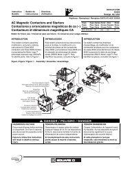
Instruction Bulletin<br />
<strong>Vacuum</strong> <strong>Circuit</strong> <strong>Breaker</strong><br />
Type VAD-3<br />
• 4.76 kV, 29 kA (250 MVA) 1200A & 2000A<br />
• 4.76 kV, 41 kA (350 MVA) 1200A & 2000A<br />
• 8.25 kV, 33 kA (500 MVA) 1200A & 2000A<br />
• 15.0 kV, 18 kA (500 MVA) 1200A & 2000A<br />
• 15.0 kV, 28 kA (750 MVA) 1200A & 2000A<br />
• 15,0 kV, 37 kA (1000 MVA) 1200A & 2000A<br />
© 1993 Square D Company All Rights Reserved<br />
Bulletin 6055-11<br />
October, 1993<br />
1
Bulletin 6055-11<br />
October, 1993<br />
NOTICE<br />
Read these instructions carefully and look at the equipment to become familiar with the device before trying to install,<br />
operate, or maintain it. The following special messages may appear throughout this bulletin to warn of potential<br />
hazards and to call attention to additional information which clarifies or simplifies a procedure.<br />
! DANGER<br />
Used where there is a hazard of severe bodily injury or death. Failure to<br />
follow a “DANGER” instruction will result in severe bodily injury or death.<br />
! WARNING<br />
Used where there is a hazard of bodily injury or death. Failure to follow a<br />
“WARNING” instruction may result in bodily injury or death.<br />
Used where there is a hazard of equipment damage. Failure to follow a<br />
“CAUTION” instruction may result in damage to equipment.<br />
Provides additional information to clarify or simplify a procedure.<br />
Square D and are Registered Trademarks of Square D Company.<br />
!<br />
CAUTION<br />
NOTE<br />
© 1993 Square D Company, all rights reserved. This bulletin may not be copied in whole or in part, or transferred to any other media, without the<br />
written permission of Square D Company.<br />
2 © 1993 Square D Company All Rights Reserved
CONTENTS PAGE<br />
1. INTRODUCTION ................................................................................................... 1<br />
Surge Protection For VAD-3 <strong>Circuit</strong> <strong>Breaker</strong>s—Statement Of Use ........... 1<br />
2. SAFETY PRECAUTIONS ...................................................................................... 2<br />
3. RECEIVING, HANDLING, AND STORAGE .................................................... 3<br />
Receiving .............................................................................................................. 3<br />
Handling .............................................................................................................. 3<br />
Storage .................................................................................................................. 3<br />
4. INITIAL CIRCUIT BREAKER PREPARATION ................................................ 4<br />
Performing A Hi-Pot Test ................................................................................. 4<br />
5. INSTALLATION .................................................................................................... 5<br />
Site Preparation And <strong>Circuit</strong> <strong>Breaker</strong> Installation ........................................ 5<br />
6. VACUUM CIRCUIT BREAKER DESCRIPTION ............................................... 6<br />
<strong>Vacuum</strong> Interrupters.......................................................................................... 6<br />
Primary Disconnects .......................................................................................... 6<br />
Operating Mechanism ....................................................................................... 6<br />
Control <strong>Circuit</strong> .................................................................................................... 6<br />
Auxiliary Switch ................................................................................................. 8<br />
Motor Limit Switch ............................................................................................ 8<br />
Motor Relay ......................................................................................................... 8<br />
Anti-Pump Relay ................................................................................................ 9<br />
Latch Check Switch ............................................................................................ 9<br />
Closing Spring Interlock .................................................................................... 9<br />
Indicators ............................................................................................................. 9<br />
7. OPERATING THE CIRCUIT BREAKER .......................................................... 10<br />
Manual Charging .............................................................................................. 10<br />
Slow Closing Feature ....................................................................................... 10<br />
Drawout Operation .......................................................................................... 11<br />
Racking In Procedure ....................................................................................... 11<br />
Racking Out Procedure ................................................................................... 12<br />
Locking Provision ............................................................................................. 12<br />
Test Position Operation ................................................................................... 12<br />
8. OPERATING MECHANISM .............................................................................. 13<br />
Drive Spring Charging .................................................................................... 13<br />
Closing Operation ............................................................................................ 14<br />
Opening Operation .......................................................................................... 15<br />
9. MAINTENANCE.................................................................................................. 16<br />
<strong>Vacuum</strong> Interrupters........................................................................................ 16<br />
Insulating Surfaces ........................................................................................... 16<br />
Mechanism ......................................................................................................... 17<br />
Lubrication......................................................................................................... 17<br />
<strong>Electric</strong>al ............................................................................................................. 17<br />
10. REPLACEMENT PARTS ..................................................................................... 18<br />
Minimum Requirements ................................................................................. 18<br />
Ordering Instructions ...................................................................................... 18<br />
11. INSTALLATION AND MAINTENANCE LOG ............................................. 19<br />
© 1993 Square D Company All Rights Reserved<br />
Bulletin 6055-11<br />
October, 1993<br />
3
Bulletin 6055-11<br />
October, 1993<br />
ILLUSTRATIONS PAGE<br />
1. <strong>Circuit</strong> breaker, front view .................................................................................... 5<br />
2. <strong>Circuit</strong> breaker, rear view ..................................................................................... 6<br />
3. Contact circuit schematic ...................................................................................... 7<br />
4. <strong>Circuit</strong> breaker, left front view without cover (18 kA, 28 kA, and 29 kA) .... 8<br />
5. <strong>Circuit</strong> breaker, right front view without cover (18 kA, 28 kA, and 29 kA) ....... 8<br />
6. <strong>Circuit</strong> breaker, front view without cover (37 kA and 41 kA) ........................ 9<br />
7. Charging the drive springs ................................................................................... 9<br />
8. Removing the closing spring .............................................................................. 10<br />
9. Slow close feature ................................................................................................. 10<br />
10. Racking mechanism in test position .................................................................. 11<br />
11. Racking mechanism in operating (connected) position ................................. 11<br />
12. Racking mechanism padlock provision ............................................................ 12<br />
13. <strong>Circuit</strong> breaker mechanism, two views ............................................................ 13<br />
14. Mainshaft mechanism .......................................................................................... 14<br />
15. Contact erosion measurement ............................................................................ 14<br />
TABLES PAGE<br />
1. Lubrication Chart ................................................................................................. 17<br />
2. Replacement Parts ................................................................................................ 18<br />
3. Pole Assembly Replacement Parts..................................................................... 18<br />
4 © 1993 Square D Company All Rights Reserved
SECTION 1—INTRODUCTION<br />
© 1993 Square D Company All Rights Reserved<br />
Bulletin 6055-11<br />
October, 1993<br />
This manual provides installation, operation, and maintenance instructions<br />
for the type VAD-3 series of horizontal drawout vacuum circuit breakers.<br />
Surge Protection For VAD-3 medium voltage vacuum circuit breakers are designed and tested<br />
VAD-3 <strong>Circuit</strong> <strong>Breaker</strong>s— in accordance with ANSI/IEEE C37.04, .06, and .09. Used in conjunction with<br />
Statement Of Use switchgear designed and tested to ANSI/IEEE C37.20.2, circuit breakers can<br />
be applied as general purpose devices.<br />
VAD-3 circuit breakers may be installed over a wide range of applications<br />
and system parameters. Several IEEE publications are available to provide<br />
guidance for use in industry practices (IEEE Color Book Series).<br />
Distribution systems can be exposed to lightning or switching surges. Older<br />
systems, with aging insulation or out-of-date standards, may be more<br />
susceptible to damage.<br />
For this reason, consider adding metal oxide surge arrestors to the circuitry<br />
on the load side of the terminals of VAD-3 circuit breakers used in retro-fit<br />
applications. Place the surge protection in the switchgear or at the equipment<br />
being protected, but not on the circuit breaker.<br />
Metal oxide arrestors limit the magnitude of prospective overvoltages, but<br />
do not affect the rate of rise (di/dt) of surge transients. Consider using surge<br />
capacitors for this additional protection.<br />
5
Bulletin 6055-11<br />
October, 1993<br />
SECTION 2—SAFETY PRECAUTIONS<br />
! DANGER<br />
HAZARD OF ELECTRICAL SHOCK OR BURN.<br />
• Only qualified electrical workers with training and experience on<br />
high voltage circuits should perform work described in this set of<br />
instructions. These workers must understand the hazards involved<br />
in working with or near high voltage equipment. Perform such work only<br />
after reading this complete set of instructions.<br />
• The successful operation of circuit breakers depends upon proper<br />
handling, installation, operation, and maintenance. Neglecting<br />
fundamental installation and maintenance requirements may lead<br />
to personal injury, as well as damage to electrical equipment or<br />
other property.<br />
• VAD-3 circuit breakers have features designed to direct proper operation,<br />
but it is not possible to eliminate every hazard with these features.<br />
Therefore, the person using this device is responsible for recognizing the<br />
potential hazards, wearing protective equipment, and taking adequate<br />
safety precautions.<br />
• Do not make any modifications to the equipment or operate the<br />
system with safety features removed. Contact your local Square D<br />
representative for additional instructions if the VAD-3 circuit breaker<br />
does not function as described in this manual.<br />
• Before performing visual inspections, tests, or maintenance on this<br />
device, disconnect all sources of electric power. Assume all circuits<br />
are live until they are completely de-energized, tested, grounded, and<br />
tagged. Pay particular attention to the design of the power system.<br />
Consider all sources of power, including the possibility of backfeeding.<br />
• Before replacing covers, carefully inspect the circuit breaker work area for<br />
tools and objects left inside the equipment.<br />
• All maintenance must be performed by qualified personnel in accordance<br />
with local codes and ordinances, and under the following conditions:<br />
– The circuit breaker must be removed from its cell and isolated from the<br />
high voltage.<br />
– Control voltage must be removed from the controls.<br />
– The circuit breaker must be in the open position.<br />
– All circuit breaker springs must be discharged.<br />
All instructions in this manual assume the customer has taken the above<br />
steps to obtain safe conditions before performing maintenance or testing.<br />
Failure to observe these precautions will result in severe personal<br />
injury or death!<br />
6 © 1993 Square D Company All Rights Reserved
SECTION 3—RECEIVING, HANDLING, AND STORAGE<br />
© 1993 Square D Company All Rights Reserved<br />
Bulletin 6055-11<br />
October, 1993<br />
Receiving Upon receipt, inspect the entire circuit breaker for damage that may have<br />
occurred in transit. Check all items against the packing list provided. Notify<br />
the transportation company and Square D immediately if there are damages<br />
or shortages.<br />
Handling Use care when uncrating and handling the circuit breaker. Roll and<br />
maneuver the circuit breaker by the handle on the front mechanism cover or<br />
by grasping the top edge of the front mechanism cover. When using a hoist,<br />
lift the circuit breaker by the holes in the frame to prevent damage.<br />
HAZARD OF EQUIPMENT DAMAGE.<br />
Never lift the circuit breaker by placing forklift bars beneath the circuit<br />
breaker frame. Never use racking arms or primary disconnects as<br />
handles.<br />
Failure to observe this precaution can result in equipment damage.<br />
Storage If the circuit breaker must be stored before it is put into operation, keep it in<br />
a clean, dry, corrosion-free area where it is protected from damage. Place<br />
the circuit breaker in its permanent location as soon as possible. If the circuit<br />
breaker will be used in switchgear employing space heaters, install it only<br />
after the heaters are operating.<br />
!<br />
CAUTION<br />
When circuit breakers are stored for prolonged periods, inspect them<br />
regularly for rusting and overall condition. Lubricate when necessary.<br />
7
Bulletin 6055-11<br />
October, 1993<br />
SECTION 4—INITIAL CIRCUIT BREAKER PREPARATION<br />
Follow these steps to prepare the circuit breaker for installation in<br />
its enclosure:<br />
1) Examine the entire circuit breaker for damage, dirt, and moisture.<br />
2) Use a clean, dry cloth to remove dirt and moisture that may have<br />
collected on the insulating parts.<br />
3) Operate the circuit breaker several times to check for proper operation.<br />
Performing A Hi-Pot Test 4) To ensure no damage has occurred during shipment, perform a hi-pot<br />
test across the open contacts of each vacuum interrupter. Then, with<br />
the circuit breaker in the closed position, perform a phase-to-ground and<br />
phase-to-phase hi-pot test for each pole. Gradually increase the voltage to<br />
the proper level. The hi-pot test voltage should be 27 kV rms or 38 kVdc<br />
for 15.0 kV, and 14 kV rms or 20 kVdc for 4.76 kV switchgear. The circuit<br />
breaker should sustain this potential for one minute.<br />
HAZARD OF PERSONAL INJURY OR EQUIPMENT DAMAGE.<br />
Observe the following instructions when performing the hi-pot test:<br />
• Do not exceed the voltages specified in step 4 above.<br />
• Keep all people at least six feet away from the circuit breaker<br />
being tested.<br />
• Perform tests only after all insulating parts are installed.<br />
• Discharge to ground the primary disconnects before handling.<br />
These areas can retain a static charge after a hi-pot test.<br />
Failure to observe these precautions can result in severe<br />
personal injury or death!<br />
5) To insert the circuit breaker into its enclosure, follow the applicable<br />
directions provided in the switchgear instruction manual.<br />
6) With the main power off, cycle the circuit breaker several times and check<br />
forproper operation.<br />
The circuit breaker is now ready for normal operation.<br />
8 © 1993 Square D Company All Rights Reserved<br />
!<br />
WARNING
SECTION 5— INSTALLATION<br />
© 1993 Square D Company All Rights Reserved<br />
Bulletin 6055-11<br />
October, 1993<br />
Site Preparation And Refer to the metal-enclosed switchgear instruction bulletin that was shipped<br />
<strong>Circuit</strong> <strong>Breaker</strong> Installation with your equipment; follow the site preparation and installation<br />
instructions found in that manual.<br />
➀ Racking Port<br />
➁ Front Mechanism Cover<br />
➂ Open Lever<br />
√ Close Lever<br />
➄ Secondary Disconnect<br />
Handle<br />
≈ Manual Charging Arm Port<br />
Δ Racking Arm<br />
➇ Counter<br />
➈ Open-Close Indicator<br />
➉ Spring Charge-Discharge<br />
Indicator<br />
➉11 Test Position Interlock<br />
Δ<br />
➀<br />
Figure 1: <strong>Circuit</strong> breaker, front view<br />
➉11<br />
➂<br />
√<br />
➄<br />
➇<br />
➁<br />
➈<br />
➉<br />
≈<br />
9
Bulletin 6055-11<br />
October, 1993<br />
SECTION 6— VACUUM CIRCUIT BREAKER DESCRIPTION<br />
<strong>Vacuum</strong> Interrupters <strong>Vacuum</strong> interrupters (figure 2), mounted vertically within the circuit<br />
breaker frame, perform the circuit breaker interruption. Consisting of a pair<br />
of butt contacts, one movable and one fixed, interrupters require only a<br />
short contact gap for circuit interruption. The resulting high-speed<br />
operation allows the entire operating sequence, from fault to clear, to be<br />
consistently performed in three cycles or less.<br />
Primary Disconnects The primary connection to the associated switchgear is through the six<br />
primary disconnects (figure 2) mounted horizontally at the rear of the<br />
circuit breaker. Do not subject the primary disconnects to rough treatment.<br />
Never use the primary disconnects as handles when maneuvering the<br />
breaker.<br />
Operating Mechanism The operating mechanism is of the stored energy type. It uses charged<br />
springs to perform breaker opening and closing functions. The operating<br />
mechanism contains all necessary controls and interlocks. It is mounted at<br />
the front of the circuit breaker for easy access during inspection and<br />
maintenance.<br />
Control <strong>Circuit</strong> Figure 3 shows a typical schematic diagram for the control circuit. The<br />
following paragraphs discuss operation of the control circuit components.<br />
The control circuit design may vary, depending upon customer requirements.<br />
Always refer to the schematic diagram for the specific equipment in question.<br />
➁<br />
➀ Primary Disconnect<br />
➁ Shutter Roller<br />
➂ Secondary Disconnect<br />
√ Code Plate<br />
➄ Ground Contact<br />
≈ <strong>Vacuum</strong> Interrupter<br />
Δ Racking Arm<br />
Figure 2: <strong>Circuit</strong> breaker, rear view<br />
10 © 1993 Square D Company All Rights Reserved<br />
Δ<br />
➂<br />
√<br />
➄<br />
≈<br />
➀
52/M<br />
1 3<br />
5 7<br />
207<br />
52MR<br />
52MR<br />
200<br />
2<br />
6<br />
201<br />
52/LS 52Y 52MR<br />
Charging/Closing<br />
<strong>Circuit</strong><br />
52Y<br />
21<br />
22<br />
52Y<br />
202<br />
52/b<br />
203<br />
52/CC<br />
209<br />
52/LC<br />
204<br />
52MR<br />
11<br />
12<br />
4<br />
3<br />
8<br />
7<br />
4<br />
9<br />
52/a<br />
205<br />
52/a<br />
210<br />
52/TC<br />
206<br />
52/a<br />
10<br />
5<br />
Trip<br />
<strong>Circuit</strong><br />
Legend<br />
52/M Spring Charging Motor<br />
52MR Motor Relay<br />
52/LS Closing Springs Limit Switch;<br />
Closed When Springs Are Discharged<br />
52Y Anti-Pump Relay<br />
52/CC Closing Coil (Spring Release Coil)<br />
52/TC Tripping Coil<br />
52/a Auxiliary Switch Contact; Open When <strong>Circuit</strong><br />
<strong>Breaker</strong> Is In Tripped (Open) Position<br />
52/b Auxiliary Switch Contact; Closed When <strong>Circuit</strong><br />
<strong>Breaker</strong> Is In Tripped (Open) Position<br />
52/LC Latch Check Switch<br />
Rear View Of <strong>Circuit</strong> <strong>Breaker</strong> Control Plug<br />
1 2 3 4 5 6 7 8 9 10 11 12<br />
5 6 7 9 10 — 13 — 14 51 52 53<br />
54 55 56 57 58 — — — 59 60 61 62<br />
13 14 15 16 17 18 19 20 21 22 23 24<br />
Figure 3: Control circuit schematic<br />
© 1993 Square D Company All Rights Reserved<br />
Bulletin 6055-11<br />
October, 1993<br />
7 10 12 14 16 21 23<br />
13 51 53 55 57 59 61<br />
5 15 9 19 13 23 17<br />
52/b 52/a 52/b 52/a 52/b 52/a 52/b<br />
6 16 10 20 14 24 18<br />
14 52 54 56 58 60 62<br />
9 11 13 15 17 22 24<br />
Auxiliary<br />
Contacts<br />
Note: <strong>Circuit</strong> breaker shown in open<br />
position with closing<br />
springs charged<br />
11
Bulletin 6055-11<br />
October, 1993<br />
Auxiliary Switch The auxiliary switch (figure 4) is a multi-stage switch used to operate circuits<br />
that depend on the position of the circuit breaker contacts. The schematic diagram in<br />
figure 3 (page 7) illustrates how each auxiliary switch stage interconnects with the<br />
circuit breaker circuitry. The stages function as follows:<br />
• Three a-type auxiliary contacts connect in series with the trip coil. Because<br />
these stages are open when the circuit breaker is in the open position,<br />
the auxiliary contacts de-energize the trip coil when the breaker is in the<br />
open position.<br />
• The b-type contact, connected in series with the closing coil, de-energizes<br />
the closing coil when the circuit breaker contacts are in the closed position.<br />
• As shown, several a-type and b-type contacts are provided for optional use.<br />
Motor Limit Switch The motor limit switch (figure 4) energizes the motor relay (figure 4) when<br />
a drive spring charging operation is required. The motor limit switch<br />
de-energizes the motor relay when the drive springs (figure 5) reach the<br />
fully charged position. As shown in the schematic diagram (figure 3), the motor<br />
limit switch is connected in the normally open position. When the drive<br />
springs are not in the fully charged position, the motor limit switch is<br />
closed.<br />
Motor Relay When energized by the closing of the motor limit switch, the motor relay<br />
energizes the spring charging motor (figure 4) through a pair of normally<br />
open contacts. The motor relay disables the closing coil (figure 5) through a<br />
pair of normally closed contacts.<br />
➈<br />
➀<br />
➂<br />
➀ MOC Operator<br />
➁ Motor Limit Switch<br />
➂ Opening Coil<br />
√ Latch Check Switch<br />
➄ Auxiliary Switch<br />
➁ √<br />
Figure 4: <strong>Circuit</strong> breaker, left front view without<br />
cover (18 kA, 28 kA, and 29 kA)<br />
➀ Return Spring (2 places)<br />
➁ Shock Absorber<br />
➂ Manual Charging Arm<br />
√ Crank Arm (2 places)<br />
12 © 1993 Square D Company All Rights Reserved<br />
➇<br />
≈ Motor Relay<br />
Δ Anti-Pump Relay<br />
➇ Spring Charging Motor<br />
➈ Return Spring<br />
Δ<br />
≈<br />
➄<br />
➁<br />
➀<br />
➄ Ratchet Arm<br />
≈ Drive Spring (2 places)<br />
Δ Closing Coil<br />
Figure 5: <strong>Circuit</strong> breaker, right front view<br />
without cover (18 kA, 28 kA, and 29 kA)<br />
➂<br />
Δ<br />
≈<br />
√<br />
➄
Figure 6: <strong>Circuit</strong> breaker, front view without<br />
cover (37 kA and 41 kA)<br />
➀ Open-Close Indicator<br />
➁ Manual Charging Arm<br />
➂ Charge-Discharge<br />
Indicator<br />
© 1993 Square D Company All Rights Reserved<br />
Figure 7: Charging the drive springs<br />
Bulletin 6055-11<br />
October, 1993<br />
Anti-Pump Relay If the closing coil circuit (52/CC, figure 3, page 7) is continuously energized, the<br />
anti-pump relay (figure 4) ensures that the circuit breaker does not “pump” open<br />
and closed in the event that a trip signal is also present. The anti-pump relay<br />
performs this function by allowing the closing coil to activate only if:<br />
• the circuit is energized<br />
• the drive springs are fully charged, and<br />
• the motor relay is de-energized<br />
The anti-pump relay activates when the close circuit and motor relay are energized.<br />
If the close circuit is energized continuously, the anti-pump relay will be latched<br />
in the energized position after the motor relay is de-energized by a pair of its own<br />
normally open contacts. When the anti-pump relay is energized, a pair of its<br />
normally closed contacts, in series with the closing coil, ensure that the closing<br />
coil cannot be energized. The closing coil activates only when the closing circuit is<br />
de-energized (de-energizing the anti-pump relay), then closed again.<br />
Latch Check Switch The latch check switch (figure 4) allows the circuit breaker to be used for<br />
instantaneous reclosing. The contacts of the latch check switch connect in series<br />
with the closing coil. When the guide cam moves out of its normal position, it<br />
activates the latch check switch. The closing circuit cannot be energized until the<br />
guide cam fully returns to its normal position and the mechanism is in position to<br />
allow a close operation.<br />
Closing Spring Interlock An interlock located between the manual trip and close lever at the bottom of the<br />
circuit breaker prevents the closing springs from “dumping” when the circuit<br />
breaker is closed. An interlock bar slides under the closing lever after the circuit<br />
breaker closes and prevents the closing lever from being pushed down.<br />
Indicators There are two indicators on the operating mechanism. The open-close indicator<br />
(figure 7) designates whether the vacuum interrupter contacts are open or closed.<br />
The charge-discharge indicator (figure 7) displays the state (charged<br />
or discharged) of the drive springs.<br />
➀<br />
➂<br />
➁<br />
13
Bulletin 6055-11<br />
October, 1993<br />
SECTION 7—OPERATING THE CIRCUIT BREAKER<br />
Manual Charging To manually charge the drive springs (figure 7, page 9), use the handle supplied<br />
with the circuit breaker to move the manual charging arm (figure 7) up and<br />
down until the drive springs are fully charged. The drive springs are fully<br />
charged when the charge-discharge indicator (figure 7) reads charged and the<br />
manual charging arm no longer advances the gear.<br />
Slow Closing Feature Occasionally, it may be necessary to manually slow close the circuit breaker.<br />
The operating mechanism has a built-in feature for this purpose. Follow the<br />
steps below to manually slow close.<br />
➀ Manual Charging Handle<br />
➁ 1/2" Bolt<br />
➂ Drive Spring<br />
HAZARD OF BODILY INJURY.<br />
Only qualified personnel should perform this operation. Stored energy in<br />
springs and sudden operation of mechanisms can cause serious bodily<br />
injury if a person touches or comes in close proximity of the mechanism.<br />
Failure to observe this precaution can result in personal injury!<br />
1. With the circuit breaker in the open position and the drive springs<br />
discharged, slide the manual charging handle onto one of the drive spring<br />
brackets (figure 8). Press up on the manual charging handle just enough to<br />
off-load the drive spring; remove the upper 1/2" bolt (figure 8). Release the<br />
drive spring pressure; remove the spring. Repeat with the other drive<br />
spring.<br />
2. Using the manual charging handle as described in the Manual Charging<br />
section above, advance the gear until the drive pawl (figure 13, page 13)<br />
rides up on the lift cam. Remove the manual charging handle.<br />
14 © 1993 Square D Company All Rights Reserved<br />
➀<br />
➁<br />
➂<br />
!<br />
➀ Close Lever<br />
➁ 1" Open-End<br />
Wrench<br />
WARNING<br />
Figure 8: Removing the closing spring Figure 9: Slow close feature<br />
➀<br />
➁
➀ Racking Arm<br />
➁ Roller In Test Position<br />
➂ Racking Port<br />
➀ Roller In Operating Position<br />
© 1993 Square D Company All Rights Reserved<br />
Bulletin 6055-11<br />
October, 1993<br />
Slow Closing Feature (cont.) 3. While pressing down on the close lever (figure 9), use a 1" open-end wrench<br />
to rotate the drive shaft until the drive pawl clears the lift cam and once<br />
again engages the gear. See figure 9 for use of the wrench. Press down on<br />
the wrench to achieve the correct direction of rotation.<br />
4. Release the close lever. Remove the 1" wrench.<br />
5. Continue using the manual charging handle to perform manual charging.<br />
The circuit breaker slowly closes with each advance of the gear.<br />
Drawout Operation The circuit breaker must be in the open position when it is racked in or out of<br />
its cubicle. The racking mechanism (figures 10 and 11) interlocks with the<br />
circuit breaker mechanism. This prevents the racking shaft from being turned<br />
when the circuit breaker is in the closed position.<br />
Racking In Procedure 1. The racking arms (figure 10) must be in the drawout position before<br />
inserting the breaker into the cell. In the drawout position, the racking arms<br />
extend toward the rear of the breaker and are just below the horizontal.<br />
2. If required, move the racking arms to the drawout position. Follow<br />
these steps:<br />
a. Open the circuit breaker.<br />
b. Insert the racking handle into the racking port (figure 10).<br />
c. Rotate the racking handle counterclockwise until the racking mechanism<br />
comes to a stop. Do not over-torque.<br />
Figure 10: Racking mechanism in test position<br />
➀<br />
➁<br />
➂<br />
!<br />
➀<br />
WARNING<br />
HAZARD OF BODILY INJURY OR EQUIPMENT DAMAGE.<br />
When the switchgear is energized, always open and close the circuit breaker<br />
and rack the circuit breaker from one position to another with the door closed.<br />
Never use force to move the circuit breaker inside the circuit breaker cell.<br />
Failure to observe these precautions can result in severe personal injury<br />
or death!<br />
Figure 11: Racking mechanism in operating<br />
(connected) position<br />
15
Bulletin 6055-11<br />
October, 1993<br />
Racking In Procedure (cont.) 3. Insert the circuit breaker into the cell until the rollers on the racking arms<br />
come into contact with the channels on the sides of the cell.<br />
4. Rotate the racking handle clockwise until the racking mechanism stops. Do<br />
not over-torque.<br />
Racking Out Procedure 1. Open the circuit breaker.<br />
2. Insert the racking handle into the racking port.<br />
3. Rotate the racking handle counterclockwise until the racking mechanism<br />
stops. Do not over-torque.<br />
4. Press down on the test position interlock (figure 1, page 5) at the lower<br />
left front of the circuit breaker; roll the circuit breaker out of the cell.<br />
Locking Provision The racking mechanism of the circuit breaker can be locked in either the test or<br />
the operating position with a multiple padlock hasp and a padlock, as shown in<br />
figure 12.<br />
Test Position Operation The secondary disconnect (figure 2, page 6) mounts on a retractable slide so that<br />
it can connect to the control circuit of the cell while the cell shutters are down<br />
and the primary connections have not been made. This provides a convenient<br />
and safe method for electrically testing the operation of the circuit breaker<br />
mechanism and control circuit. Test position operation is achieved by following<br />
these steps:<br />
1. Insert the circuit breaker into the test position of the cell by following<br />
steps 1through 3 of the Racking In Procedure section on page 11. (Do not<br />
rack the circuit breaker into the cell.)<br />
2. Pull the secondary disconnect handle (figure 2, page 6) out of its<br />
retaining clip; rotate it down so that it protrudes straight out from the<br />
circuit breaker.<br />
3. Lift slightly on the secondary disconnect handle and push it into the<br />
circuit breaker until the control circuits connect.<br />
4. The control circuit of the circuit breaker is now connected with that of<br />
the cell.<br />
5. Retract the secondary disconnect by reversing the above procedure.<br />
Figure 12: Racking mechanism<br />
padlock provision<br />
16 © 1993 Square D Company All Rights Reserved
SECTION 8—OPERATING MECHANISM<br />
© 1993 Square D Company All Rights Reserved<br />
Bulletin 6055-11<br />
October, 1993<br />
Drive Spring Charging Place the interrupter contacts in the open position; ensure that the drive<br />
springs (figure 13) and return springs (figure 5, page 8) are discharged. When<br />
power is supplied to the circuit breaker control circuit, the charging motor<br />
(figure 13) is energized. The eccentric, mounted on the charging motor shaft,<br />
drives the ratchet arm (figure 13) backward and forward.<br />
➇<br />
➈<br />
➄<br />
➀ Ratchet Arm<br />
➁ Drive Pawl<br />
➂ Lift Cam<br />
√ Gear<br />
➄ Drive Shaft<br />
≈ Manual<br />
Charging Arm<br />
Δ Mainshaft<br />
➇ Drive Springs<br />
➈ Crank Arm<br />
➉ Closing Coil<br />
➉11 Charging Motor<br />
With each forward stroke of the ratchet arm, the spring-loaded drive pawl<br />
(figure 13) mounted on the ratchet arm engages a tooth on the gear (figure 13).<br />
The gear advances a few degrees clockwise. The drive pawl (figure 13) holds<br />
the gear in position while the drive pawl makes its reverse stroke to engage<br />
another tooth. The gear is free to rotate on the drive shaft (figure 13).<br />
As the gear advances, the drive pin mounted on the gear face engages and<br />
rotates the lift cam (figure 13). Because the lift cam is keyed to the drive shaft,<br />
the drive shaft rotates with the lift cam.<br />
The crank arms (figure 13) rotate with the drive shaft and pull the drive springs<br />
to the charged position. As the springloads pass top dead center and attempt to<br />
discharge, the closing roller on the drive cam contacts the close cam (figure 14,<br />
page 14). The drive springs stay in this charged position until closing is<br />
initiated.<br />
When the drive springs are fully charged, the charging motor limit switch<br />
contacts open, de-energizing the charging motor. Simultaneously, the raised<br />
➉11<br />
Figure 13: <strong>Circuit</strong> breaker mechanism, two views<br />
➂<br />
≈<br />
Δ<br />
➉<br />
➇<br />
➀<br />
➁<br />
≈<br />
√<br />
➄<br />
17
Bulletin 6055-11<br />
October, 1993<br />
Drive Spring Charging (cont.) surface on the lift cam lifts the drive pawl above the gear. This allows the<br />
charging motor and ratchet arm to coast smoothly to a stop.<br />
Closing Operation Once the drive springs are charged, close the circuit breaker by energizing the<br />
closing coil (figure 13) or by manually pressing the close lever (figure 9, page<br />
10).<br />
➀ Close Cam<br />
➁ Drive Cam<br />
➂ Drive Cam Roller<br />
√ Guide Cam<br />
➄ Trip Cam<br />
≈ Drive Cam Follower<br />
Δ Main Link<br />
➇ Cross Bar Pivot<br />
➈ Cross Bar<br />
➉ Racking Arm<br />
➂<br />
➄<br />
√<br />
➉<br />
Figure 14: Mainshaft mechanism<br />
➈<br />
18 © 1993 Square D Company All Rights Reserved<br />
➀<br />
➁<br />
≈<br />
Δ<br />
➇<br />
!<br />
WARNING<br />
HAZARD OF BODILY INJURY OR EQUIPMENT DAMAGE.<br />
The manual closing lever should be used only in the test position, or if the<br />
power to the circuit breaker has been removed.<br />
Failure to observe this precaution can result in personal injury or<br />
equipment damage!<br />
This disengages the close cam (figure 14) from the closing roller and allows the<br />
drive springs to discharge. The discharging drive springs rotate the drive shaft<br />
(figure 13) counterclockwise. This rotation also gives the drive cam (figure 14) a<br />
counterclockwise rotation.<br />
The rotation of the drive cam pushes the drive cam follower (figure 14) down.<br />
Linkage with the mainshaft (figure 13) causes a downward motion of the<br />
racking arms (figure 14). The resulting upward motion of the rear of the<br />
racking arms closes the vacuum interrupter contacts and charges the bias<br />
springs (figure 15).<br />
➀<br />
➁<br />
➀ <strong>Vacuum</strong> Interrupter<br />
➁ Bias Spring<br />
“E”<br />
Figure 15: Contact erosion measurement
Bulletin 6055-11<br />
October, 1993<br />
Closing Operation (cont.) The counterclockwise rotation of the drive shaft also rotates the lift cam out<br />
of contact with the drive pin. Because the gear rotates freely on the drive<br />
shaft, the gear remains stationary. The rotation of the lift cam allows the<br />
drive pawl to engage the gear. The motor limit switch (figure 4, page 8)<br />
energizes the charging motor which once again charges the drive springs.<br />
Opening Operation With the return springs charged and the circuit breaker closed, the<br />
operating mechanism is ready to perform an opening operation. If the open<br />
lever (figure 1, page 5) is pushed or if the opening coil (figure 4, page 8) is<br />
energized, the trip cam rotates counterclockwise away from the guide cam<br />
(figure 14). The force of the charged return springs pulling up on the<br />
mainshaft causes the guide cam to move out toward the front of the<br />
mechanism. This allows the drive cam follower to collapse off the top of the<br />
drive cam. The mainshaft is pulled up, pulling the front of the racking arms<br />
up. The resulting downward motion of the rear of the racking arms opens<br />
the vacuum interrupter contacts (figure 15).<br />
© 1993 Square D Company All Rights Reserved<br />
19
Bulletin 6055-11<br />
October, 1993<br />
SECTION 9 —MAINTENANCE<br />
Because of wide variations in operating uses and environments, each<br />
operating company should develop a maintenance schedule, based on<br />
operating experience, which will ensure proper circuit breaker condition.<br />
Until such a schedule is determined, inspect circuit breakers after three<br />
years or every 3,000 operations, whichever occurs first.<br />
Also inspect circuit breakers after severe fault operations and record any<br />
contact erosion. The following paragraphs discuss proper inspection and<br />
maintenance procedures.<br />
HAZARD OF PERSONAL INJURY OR EQUIPMENT DAMAGE.<br />
Always remove the circuit breaker from its cubicle, and discharge the<br />
drive springs and return springs, before performing any maintenance or<br />
repair work.<br />
Failure to observe these precautions could result in personal injury<br />
or death, or equipment damage!<br />
<strong>Vacuum</strong> Interrupters To ensure reliable interruption, perform the following two checks:<br />
1. Contact erosion: Any contact erosion results in a reduction of spring<br />
overtravel. Contact erosion can be determined by closing the circuit<br />
breaker and measuring spring overtravel. Spring overtravel is<br />
represented by dimension “E” in figure 15. The difference between this<br />
measurement and the original spring overtravel, measured when the<br />
interrupter was first put into service, represents contact erosion.<br />
Spring overtravel is factory set at 0.210" (5.3 mm) for a new circuit<br />
breaker rated 23 kA or less maximum interrupting. For a new circuit<br />
breaker rated above 23 kA maximum interrupting, spring overtravel is<br />
0.188" (4.8 mm). The vacuum interrupter reaches the end of its life when<br />
spring overtravel has been reduced to 0.085" (2.2 mm) on a circuit<br />
breaker rated 23 kA or less maximum interrupting, or 0.060" (1.5 mm) on<br />
a circuit breaker rated above<br />
23 kA maximum interrupting.<br />
2. Hi-pot test: Hi-pot test the circuit breaker in accordance with the<br />
instructions provided in the Initial <strong>Breaker</strong> Preparation section, page 4,<br />
item 4.<br />
If, because of contact erosion or hi-pot test failure, a vacuum bottle must<br />
be replaced, order a complete pole assembly (see table 3 on page 16).<br />
<strong>Vacuum</strong> interrupter contacts are sealed using fragile metal bellows and<br />
are sensitive to excessive torque and handling. See the caution on page<br />
16.<br />
Insulating Surfaces Using a clean, dry cloth, remove all dirt and moisture from insulating parts.<br />
20 © 1993 Square D Company All Rights Reserved<br />
!<br />
WARNING
© 1993 Square D Company All Rights Reserved<br />
!<br />
WARNING<br />
Bulletin 6055-11<br />
October, 1993<br />
Mechanism Inspect the entire circuit breaker and operating mechanism for loose<br />
hardware and worn or broken parts. Check all wiring for loose connections<br />
and damaged insulation. Inspect all bearings and contact surfaces for<br />
damage or excessive wear.<br />
Lubrication All ball and roller bearings used in these circuit breakers are sealed; they do<br />
not require lubrication.<br />
The lubrication chart in table 1 gives the location of each lubrication point<br />
and the method of lubrication required. Lubricate after 3,000 operations or<br />
three years, whichever occurs first.<br />
Severe operating conditions may warrant different lubrication intervals and<br />
procedures. Variations should be based on the experience of the operating<br />
company.<br />
<strong>Electric</strong>al Ensure that all electrical connections are tight and clean.<br />
HAZARD OF BODILY INJURY OR EQUIPMENT DAMAGE.<br />
Work which requires disassembly of the mechanism or pole<br />
assembly must be performed by qualified electrical workers who<br />
have access to appropriate adjustment instructions. See section 10<br />
of this manual for these adjustment instructions.<br />
When not following these instructions, disassembly and reassembly<br />
of this circuit breaker can cause improper operation, resulting in<br />
damage to the circuit breaker and injury to the operator. If you have<br />
questions, contact the Square D Company, Smyrna service<br />
department, at<br />
(615) 459-5026.<br />
Failure to observe this precaution can result in personal injury<br />
or equipment damage!<br />
Lubrication Point<br />
Table 1<br />
Lubrication Chart<br />
Method of Lubrication<br />
During Maintenance Period<br />
Gear teeth Wipe clean and apply lubricant.*<br />
Contact surfaces on guide cams Wipe clean and apply lubricant.*<br />
and trip latch<br />
Motor eccentric and eccentric roller Wipe clean and apply lubricant to the slot<br />
in the ratchet arm.*<br />
Silver-plated primary disconnect Wipe clean and apply an extreme<br />
contacts and grounding contacts pressure grease, such as Mobilux EP 1,<br />
Square D part number 1615-100790.<br />
* Use Mobilgrease 28, Square D part number 1615-100950, or equivalent.<br />
21
Bulletin 6055-11<br />
October, 1993<br />
SECTION 10—REPLACEMENT PARTS<br />
Minimum Requirements Maintain sufficient replacement parts in stock to ensure prompt<br />
replacement of worn, broken, or damaged parts.<br />
Tables 2 and 3 list factory-recommended replacement parts. Each<br />
replacement part is shipped with complete assembly and adjustment<br />
instructions.<br />
Because of wide variation in operating uses and environments, the<br />
recommended parts are presented only as a minimum requirement. Each<br />
operating company should develop its own parts stock, based on operating<br />
experience, to maintain proper circuit breaker condition.<br />
Ordering Instructions When ordering replacement parts:<br />
• Always specify the complete rating information and circuit breaker<br />
serial number.<br />
• Specify part number, description of part, and the catalog from which this<br />
information is taken.<br />
Table 2<br />
Replacement Parts<br />
Description Part No.<br />
Rated<br />
Voltage<br />
Charging Motor 44068-505-50 48 Vdc<br />
44068-505-51 125 Vdc<br />
44068-505-52 250 Vdc<br />
44068-505-51 120 Vac<br />
44068-505-52 240 Vac<br />
Motor Relay 44068-506-50 48 Vdc<br />
44068-506-51 125 Vdc<br />
44068-506-52 250 Vdc<br />
44068-506-53 120 Vac<br />
44068-506-54 240 Vac<br />
Anti-Pump Relay 44068-507-50 48 Vdc<br />
44068-507-51 125 Vdc<br />
44068-507-52 250 Vdc<br />
44068-507-53 120 Vac<br />
44068-507-54 240 Vac<br />
Closing Solenoid 44068-508-50 48 Vdc<br />
44068-508-51 125 Vdc<br />
44068-508-52 250 Vdc<br />
44068-508-53 120 Vac<br />
44068-508-54 240 Vac<br />
Trip Solenoid 44068-509-50 24 Vdc<br />
44068-509-51 48 Vdc<br />
44068-509-52 125 Vdc<br />
44068-509-53 250 Vdc<br />
44068-509-54 120 Vac<br />
44068-509-55 240 Vac<br />
Main Contact (1200A) 44068-516-50 —<br />
Main Contact (2000A) 44068-516-51 —<br />
Ground Contact 44068-510-50 —<br />
Latch Check Switch 44068-511-50 —<br />
Control Power Plug Ass’y 44068-503-50 —<br />
Auxiliary Switch 44068-512-50 —<br />
Closing Spring Limit Switch 44068-513-50 —<br />
22 © 1993 Square D Company All Rights Reserved<br />
Table 3<br />
Pole Assembly Replacement Parts<br />
<strong>Circuit</strong><br />
<strong>Breaker</strong><br />
Part No.<br />
4.76 kV 29 kA 1200 A 44068-514-50<br />
4.76 kV 29 kA 2000A 44068-515-50<br />
4.76 kV 41 kA 1200A 44068-514-51<br />
4.76 kV 41 kA 2000A 44068-515-51<br />
8.25 kV 33 kA 1200A 44068-514-52<br />
8.25 kV 33 kA 2000A 44068-515-52<br />
15.0 kV 18 kA 1200A 44068-514-53<br />
15.0 kV 18 kA 2000A 44068-515-53<br />
15.0 kV 28 kA 1200A 44068-514-54<br />
15.0 kV 28 kA 2000A 44068-515-54<br />
15.0 kV 37 kA 1200A 44068-514-55<br />
15.0 kV 37 kA 2000A 44068-515-55
SECTION 11—INSTALLATION AND MAINTENANCE LOG<br />
© 1993 Square D Company All Rights Reserved<br />
Bulletin 6055-11<br />
October, 1993<br />
23
Square D Company<br />
330 Weakley Road<br />
Smyrna, TN 37167 U.S.A.<br />
Order No. 6055IM9207 FP 5M 10/93<br />
Printed in U.S.A.<br />
Replaces bulletin dated 4/90 Part No. 6055-11