rfi : project for creation of specialized test facilities - Indian Army
rfi : project for creation of specialized test facilities - Indian Army
rfi : project for creation of specialized test facilities - Indian Army

You also want an ePaper? Increase the reach of your titles
YUMPU automatically turns print PDFs into web optimized ePapers that Google loves.
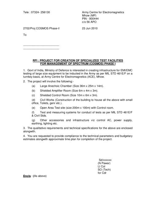
Tele : 07324- 256130 <strong>Army</strong> Centre <strong>for</strong> Electromagnetics<br />
Mhow (MP)<br />
PIN - 900444<br />
c/o 56 APO<br />
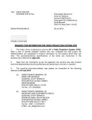
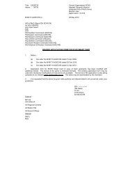
2702/Proj COSMOS Phase-I/ 23 Jun 2010<br />
To<br />
_______________________<br />
_______________________<br />
RFI : PROJECT FOR CREATION OF SPECIALIZED TEST FACILITIES<br />
FOR MANAGEMENT OF SPECTRUM (COSMOS) PHASE I<br />
1. Govt <strong>of</strong> India, Ministry <strong>of</strong> Defence is interested in creating infrastructure <strong>for</strong> EMI/EMC<br />
<strong>test</strong>ing <strong>of</strong> large size equipment to be inducted in the <strong>Army</strong> as per MIL STD 461E/F on a<br />
turnkey basis, at <strong>Army</strong> Centre <strong>for</strong> Electromagnetics (ACE), Mhow.<br />
2. The <strong>project</strong> will involve the following:-<br />
(a) Large Anechoic Chamber (Size 36m x 25m x 14m).<br />
(b) Shielded Amplifier Room (Size 6m x 4m x 3m).<br />
(c) Shielded Control Room (Size 10m x 6m x 3m).<br />
(d) Civil Works (Construction <strong>of</strong> the building to house all the above with small<br />
<strong>of</strong>fice, Toilets, genr etc.).<br />
(e) Open Area Test site (size 200m x 100m) with Control room.<br />
(f) Test and measuring systems <strong>for</strong> conduct <strong>of</strong> <strong>test</strong>s as per MIL STD 461E/F<br />
& Civil Stds.<br />
(g) Other accessories and infrastructure viz control AC, power supply,<br />
earthing, lighting etc.<br />
3. The qualitative requirements and technical specifications <strong>for</strong> the above are enclosed<br />
alongwith.<br />
4. You are requested to provide compliance to the technical parameters and budgetary<br />
estimates alongwith approximate time plan <strong>for</strong> completion <strong>of</strong> the <strong>project</strong>.<br />
Encls : (As above)<br />
Sd/xxxxxx<br />
(N Pawar)<br />
Lt Col<br />
SO (Tech)<br />
<strong>for</strong> Cdr
Introduction<br />
PART I - GENERAL INFORMATION<br />
1. As per DPP – 08, all Communication Electronic (CE) and Non CE equipment that are<br />
proposed <strong>for</strong> induction into the <strong>Indian</strong> <strong>Army</strong> are to be evaluated <strong>for</strong> compliance to<br />
Electromagnetic Compatibility (EMC) as per laid down Military Standards (MIL-STD) or<br />
Commercial Standards like FCC, CISPR, EN, etc.<br />
2. The <strong>test</strong>s are conducted as per MIL-STDs inside an anechoic chamber which provides<br />
adequate attenuation from the atmospheric ambient electromagnetic (EM) level. This chamber<br />
is required to house the EMC <strong>test</strong> system which is required to capture and analyse the<br />
emissions from the Equipment under Test (EUT).<br />
3. It is proposed to establish <strong>test</strong> and evaluation <strong>facilities</strong> to be set up at Mhow as part <strong>of</strong><br />
Creation <strong>of</strong> Specialised Test Facilities <strong>for</strong> Management <strong>of</strong> Spectrum (Project COSMOS). The<br />
<strong>project</strong> has been <strong>for</strong>mulated <strong>for</strong> a 3 phased implementation.<br />
4. This RFI lays down the DPR <strong>for</strong> such <strong>test</strong> and evaluation setup to be procured/<br />
developed/ constructed during Phase – I <strong>of</strong> the Project COSMOS.<br />
Proposed Employment<br />
5. The large anechoic chamber, OATS and associated <strong>test</strong> and measurement equipment<br />
will be employed <strong>for</strong> conduct <strong>of</strong> EMI/ EMC compliance <strong>test</strong>ing <strong>of</strong> CE and Non-CE equipment<br />
that are proposed <strong>for</strong> induction into the <strong>Indian</strong> <strong>Army</strong> <strong>for</strong> usage at ACE, Mhow. The detailed<br />
purpose is as given below:-<br />
(a) The large anechoic chamber, OATS and the associated <strong>test</strong> and measurement<br />
equipment will be used to per<strong>for</strong>m plat<strong>for</strong>m level EMC compliance <strong>test</strong>ing on weapon<br />
systems, avionics and sub-systems, CE and Non CE equipments, military vehicles and<br />
systems, Commercial <strong>of</strong>f the Shelf (COTS) equipment, etc <strong>of</strong> large dimensions (L x W x<br />
H= 10 m x 10 m x 08 m) and weighing upto 80 tons<br />
(b) Proposed chamber and OATS should be fully compliant to per<strong>for</strong>m EMC<br />
measurements according to the following EMC standards adopted by <strong>Indian</strong> Defence<br />
Forces:-<br />
(i) JSG – 0261 (1999), MIL-STD-461E and F. Radiated Emission (RE)/<br />
Radiated Susceptibility (RS) measurements, at 1m measurement distance from<br />
30 Hz to 40 GHz or any other Military Standards adopted by the <strong>Indian</strong> <strong>Army</strong> at<br />
the time <strong>of</strong> execution <strong>of</strong> the <strong>project</strong>.<br />
(ii) Commercial Standards like FCC, CISPR, EN, IEC, IEEE, ANSI, etc.<br />
(c) Important note: It is also planned to use the chamber <strong>for</strong> antenna and radio<br />
frequency measurements in higher frequency ranges. There<strong>for</strong>e it is required that the<br />
chamber is not lined with ferrite and hybrids, due to their limited reflectivity, but with<br />
pyramidal foam absorbers only, <strong>of</strong>fering suitable per<strong>for</strong>mances at high frequencies.<br />
6. Compliance <strong>of</strong> SI Units. The proposed system along with its components, manuals<br />
and s<strong>of</strong>tware should be based on the International System <strong>of</strong> Units (SI Units).<br />
7. Date <strong>of</strong> Availability. The complete system should be available <strong>for</strong> user trials within<br />
eighteen months <strong>of</strong> allotment <strong>of</strong> <strong>project</strong>.
General<br />
PART II – PHYSICAL CHARACTERISTICS<br />
8. The large anechoic chamber, OATS and associated <strong>test</strong> and measurement equipment<br />
will be used <strong>for</strong> <strong>test</strong> and measurement purpose only is required to function in a controlled<br />
environment without any reduction in its per<strong>for</strong>mance level.<br />
9. Classification.<br />
(a) The large anechoic chamber will be classified as Test Chamber (Large).<br />
(b) The Open Area Test Site will be classified as OATS.<br />
(c) The <strong>test</strong> and measurement equipment will be classified as EMC Test Equipment.<br />
10. Cabling. All cabling will be concealed either underground or in the walls running<br />
through good quality conduit pipes. The cabling will be so designed that the connectors are<br />
easily accessible as well as provide favourable ergonomic environment.<br />
PART – III: OPERATIONAL PARAMETERS<br />
11. The detailed specifications <strong>of</strong> the large anechoic chamber, OATS and associated <strong>test</strong><br />
and measurement equipment to be procured are given in succeeding paragraphs as mentioned<br />
below:-<br />
(a) Part – III (a). Large Anechoic Chamber.<br />
(b) Part – III (b). Open Area Test Site (OATS).<br />
(c) Part – III (c). Test and Measurement Equipment.<br />
Part – III (a): LARGE ANECHOIC CHAMBER<br />
12. Large Anechoic Chamber Details. The chamber shall be divided into the following<br />
segments:-<br />
(a) Anechoic Chamber.<br />
(b) Control Room.<br />
(c) Shielded Amplifier Room.<br />
(d) Power Control and Distribution Room.<br />
(e) Associated civil works including construction <strong>of</strong> the parent building.<br />
13. Dimension <strong>of</strong> Parent Building <strong>for</strong> Housing Large Anechoic Chamber. The anechoic<br />
chamber, control room, amplifier room and <strong>of</strong>fice areas will be housed inside a parent building<br />
<strong>of</strong> dimension L x W x H = 56 m x 30 m x 16 m. The power control and distribution room will be<br />
housed inside a building <strong>of</strong> dimension L x W x H = 6 m x 6 m x 5 m adjoining the parent<br />
building. The details <strong>of</strong> the construction and other aspects are given in succeeding paragraphs.<br />
A diagrammatic representation <strong>of</strong> the parent building is given at Appendix ‘A’.
(a) Requirement <strong>for</strong> Building Housing Large Size Anechoic Chamber (AC)<br />
Complete structure including the walls and ceiling to be RCC. The size <strong>of</strong> this<br />
portion <strong>of</strong> the building will be 40m x 30m x 16m. (Inner dimensions). In order to<br />
withstand the load <strong>of</strong> vehicle under <strong>test</strong>, floor in AC should be realized by copper foil<br />
shielding. Proposed steps and scope <strong>of</strong> work are:-<br />
(i) Ground Plane <strong>of</strong> minimum 10mm sheet steel welded RF contact to the<br />
shielding at the peripheral. Such realized floor should withstand tracked and<br />
wheeled vehicles up to 80 tons.<br />
(ii) Building to have a main door (pneumatic) <strong>of</strong> size not less than 12m (W) x<br />
10m (H).<br />
(iii) Building to have two more doors <strong>of</strong> size not less than 1538mm (W) x<br />
2118mm (H).<br />
(b) Requirement <strong>for</strong> Building Housing Shielded Control Room. The size <strong>of</strong> this<br />
portion <strong>of</strong> the building will be 14m x 10m x 05m. The details <strong>of</strong> the building are given<br />
below:-<br />
(i) Building to have a main door <strong>of</strong> size not less than 1013mm (W) x<br />
2118mm (H).<br />
(ii) Building to have other door <strong>of</strong> size not less than 1538mm (W) x 2118mm<br />
(H) (Common door between AC and CR).<br />
(c) Requirement <strong>for</strong> Building Housing Shielded Amplifier Room. The size <strong>of</strong><br />
this portion <strong>of</strong> the building will be 14m x 08m x 05m. The details <strong>of</strong> the building are given<br />
below:-<br />
(i) Building to have a main door <strong>of</strong> size not less than 1238mm (W) x<br />
2118mm (H).<br />
(ii) Building to have other door <strong>of</strong> size not less than 1538mm (W) x 2118mm<br />
(H) (Common door between AC and AR).<br />
(d) Miscellaneous Requirements.<br />
(i) There is a requirement <strong>of</strong> a room <strong>of</strong> dimension 6m x 6m x 5m <strong>for</strong> housing<br />
two x 11.25 KVA generators.<br />
(ii) There is a requirement <strong>of</strong> a room <strong>of</strong> dimension 10m x 6m x 5m <strong>for</strong><br />
housing two toilets (01 x Gents and 01 x Ladies Toilet).<br />
(iii) There is a requirement <strong>of</strong> a room <strong>of</strong> dimension 12m x 8m x 5m <strong>for</strong><br />
housing the <strong>of</strong>fice complex.<br />
(e) Protection against Lightning. Suitable lightning protection infrastructure to<br />
cater <strong>for</strong> umbrella coverage <strong>of</strong> 100meter diameter area at 25 meter centre height will be<br />
provided <strong>for</strong>.<br />
(f) Requirement <strong>of</strong> Internal Cabling <strong>for</strong> Internet, LAN and Cable TV. There is a<br />
requirement <strong>of</strong> providing Fiber optic type <strong>of</strong> cabling <strong>for</strong> extending internet services and<br />
LAN to the control room <strong>of</strong> the specialised building. In addition provision <strong>of</strong> providing<br />
cable TV access <strong>for</strong> viewing the system inside the anechoic chamber from the control<br />
room must also be catered <strong>for</strong> with required Fiber optic cabling.
14. Shielded Rooms Dimensions<br />
(a) The Anechoic Chamber (AC) should have following minimum shield to shield<br />
dimensions: L x W x H = 36 m x 25 m x 14 m.<br />
(b) Control Room (CR) should have following minimum shield to shield dimensions:<br />
L x W x H = 10 m x 06 m x 03 m.<br />
(c) Shielded Amplifier Room (AR) should have following minimum shield to shield<br />
dimensions: L x W x H = 06 m x 04 m x 03 m.<br />
Operational Characteristics<br />
15. The large anechoic chamber control room and shielded amplifier room should have the<br />
following minimum capabilities:-<br />
(a) The chamber should be modular, self-standing (self-supported), and independent<br />
from host building.<br />
(b) The chamber wall and ceiling construction should consist <strong>of</strong> pre-fabricated<br />
shielding modules <strong>of</strong> technical characteristics as given in subsequent paragraphs.<br />
(c) The structure design should take into consideration the seismic conditions <strong>of</strong> the<br />
site <strong>of</strong> the installation.<br />
(d) The structure must be guaranteed against corrosion <strong>for</strong> a minimum <strong>of</strong> 20 years.<br />
(e) The shielding effectiveness must be in consonance with requirements laid down<br />
in MIL-STD 285 and IEEE 299.<br />
(f) The shielded enclosure must provide good earthing with resistance not<br />
exceeding 0.5 Ω.<br />
Technical Characteristics<br />
16. The technical characteristics and design details <strong>of</strong> the construction <strong>of</strong> each room/<br />
chamber are given in succeeding paragraphs.<br />
17. Large Size Anechoic Chamber<br />
(a) Walls and Ceiling Construction.<br />
(i) The Anechoic Chamber should be modular, self-standing (selfsupported),<br />
and independent from host building.<br />
(ii) The chamber wall and ceiling construction should consist <strong>of</strong> prefabricated<br />
shielding modules compliant with DIN1623 and EN10142 standards.<br />
(iii) The panels should be linked together seamlessly without gaps (without<br />
gaskets, inserts or washers).<br />
(b) Absorbers. RF Pyramidal absorbers will be affixed on all four walls and the<br />
ceiling. In addition, removable RF absorbers will be laid on ground plane as required.<br />
The technical specifications <strong>of</strong> the RF absorbers will be as given below:-<br />
(i) All pyramidal absorbers assembly should be non combustible and must<br />
comply to fire class DIN 4102 A2<br />
(ii) Absorbers should be capable <strong>of</strong> handling upto 200 V/m continuous and<br />
600 V/m pulse power (20% duty cycle).<br />
(iii) Power handling capability <strong>of</strong> the absorbers should be greater than 1.2<br />
Watt/ cm 2 .<br />
(iv) The absorption at normal incidence <strong>for</strong> entire range <strong>of</strong> the RF absorbers<br />
will be as per Table – I given below.
TABLE – I Absorption at normal incidence<br />
Frequency Minimum absorption<br />
80 MHz - 250 MHz 6 dB<br />
above 250 MHz 10 dB<br />
(v) The shielding effectiveness must be in consonance with requirements laid<br />
down in MIL-STD 285 and IEEE 299 or as per la<strong>test</strong> active IEEE standards.<br />
(c) Doors. The proposed chambers should be fitted with RF shielded doors, in order<br />
to allow entrance <strong>of</strong> EUT and personnel. The general characteristics <strong>of</strong> the doors are<br />
given below:-<br />
(i) Very strong mechanical construction to guarantee long term per<strong>for</strong>mance.<br />
(ii) RF sealing should be made to prevent leakage <strong>of</strong> emissions from within<br />
the chamber enclosure.<br />
(iii) Following number <strong>of</strong> doors are required:-<br />
(aa) One piece automatic sliding door with clear dimensions <strong>of</strong><br />
minimum 12 m (W) x 10 m (H) fully automatic operation with pneumatic<br />
latching and with manual override.<br />
(ab) One piece automatic plat<strong>for</strong>m <strong>for</strong> sliding door, capable <strong>of</strong> taking a<br />
tracked vehicle’s load <strong>of</strong> approximately 100 tons when latched.<br />
(ac) Two pieces <strong>of</strong> hinged personnel access doors with clear<br />
dimensions <strong>of</strong> not less than 1538mm (W) x 2118mm (H), automatic<br />
operation with pneumatic latching and with manual override will be<br />
provided. One door <strong>for</strong> direct access to the control room and the other <strong>for</strong><br />
direct access to the amplifier room from the anechoic chamber.<br />
(ad) The two personnel doors will be provided with separate manual<br />
removable ramp <strong>for</strong> material handling with load bearing capacity <strong>of</strong> 500<br />
Kg.<br />
(iv) All doors must have interlock systems fitted <strong>for</strong> automatic operation <strong>of</strong><br />
safety locks.<br />
(d) Air conditioning. The entire building housing the anechoic chamber, control<br />
room, amplifier room and <strong>of</strong>fices must be centrally air conditioned.<br />
(e) Exhaust Gas Extraction System. The exhaust gas extraction system must be<br />
capable <strong>of</strong> gas extraction at the rate <strong>of</strong> 25000m 3 per hour with matching high<br />
temperature resistant hoses and tubes capable <strong>of</strong> withstanding temperatures up to<br />
1800 0 C.
(f) Ventilation. The shielded rooms should be equipped with honeycomb air<br />
vents, to ensure right air flow and ventilation inside the chamber.<br />
(i) All honeycombs must have cut <strong>of</strong>f frequency <strong>of</strong> 40 GHz.<br />
(ii) All honeycombs must be delivered with a connection flange in order to<br />
facilitate the fixation <strong>of</strong> air ducts <strong>for</strong> exhaust system.<br />
(iii) 40 pieces <strong>of</strong> honeycomb inserts <strong>of</strong> dimensions (400mm x 400mm) with<br />
cut-<strong>of</strong>f frequency <strong>of</strong> 40 GHz are <strong>for</strong>eseen as a minimum requirement.<br />
(g) Electrical Installation. The electrical distribution should be made from the<br />
filters to the connection panel using steel electrical ducts with covers fixed and grounded<br />
under the raised floor. As the chamber would be lined with absorbers on the inner walls,<br />
and in order to facilitate the access to the electrical distribution box, all distribution boxes<br />
must be made up <strong>of</strong> shielded material with an opening available outside the chamber.<br />
(h) Lighting. Lighting should be homogeneous with 300 Lux on the floor. For this<br />
adequate number <strong>of</strong> light points with electrical lifting (up/ down) system should be made<br />
available.<br />
(j) Automation <strong>of</strong> Antenna Mast. A fully automatic antenna mast system<br />
capable <strong>of</strong> scanning from 0.9m to 6m height needs to be provided.<br />
(k) Automation <strong>of</strong> Turntable. There is a requirement <strong>of</strong> a fully automatic<br />
turntable capable <strong>of</strong> withstanding a load <strong>of</strong> 60 Tons with rotation <strong>of</strong> + 190 0 and – 190 0 by<br />
an AC Drive which can be switched ON/ OFF during <strong>test</strong>ing.<br />
(l) CCTV Systems. Quantity three colour CCTV systems capable <strong>of</strong> functioning in<br />
a RF field <strong>of</strong> 200 V/m must be provided.<br />
(m) Intercom System. 1 x audio system capable <strong>of</strong> functioning in a RF field <strong>of</strong> 200<br />
V/m must be provided.<br />
(n) Fire Detection System. A centralised firedetection unit common to the AC, CR,<br />
AR and <strong>of</strong>fices must be installed.<br />
(o) Tests to be conducted inside the AC. The following compliance level <strong>test</strong>s are<br />
to be per<strong>for</strong>med inside the AC:-<br />
(i) MIL-STD 461 F edition 10 Dec 2007.<br />
(ii) CISPR 11 and CISPR 22.<br />
(iii) EN 55011 and EN 55022.<br />
(iv) IEC 61000-4-3<br />
(v) Automotive Directive 95/54/EG<br />
(vi) ISO 7637 and 11452-2<br />
(vii) CISPR 25<br />
18. Control Room(CR) (Shielded Room).<br />
(a) Dimensions. The internal dimensions <strong>of</strong> the CR would be 10m (L) x 6m<br />
(W) x 3m (H).<br />
(b) Entrance Door The entrance door would be a single wing edge door<br />
pneumatic latching with a clear opening dimension <strong>of</strong> not less than 1013mm (W) x<br />
2118mm (H). The threshold would be situated at 150mm height with an indication <strong>of</strong><br />
“Test in progress” mark.
(c) Honeycombs <strong>for</strong> ventilation. Quantity six units <strong>of</strong> 400mm x 400mm (40<br />
GHz cut-<strong>of</strong>f) with flange <strong>for</strong> easy connection <strong>of</strong> HVAC conduits must be provided.<br />
(d) Per<strong>for</strong>mance. The CR must provide shielding effectiveness in consonance with<br />
requirements laid down in MIL-STD 285 and IEEE 299 or as per la<strong>test</strong> active IEEE<br />
standards.<br />
19. Amplifier Room (Shielded Room).<br />
(a) Dimensions. The internal dimensions <strong>of</strong> the AR would 6m (L) x 4m (W)<br />
x 3m (H).<br />
(b) Entrance Door The entrance door would be a single wing edge door<br />
pneumatic latching with a clear opening dimension <strong>of</strong> not less than 1238mm (W) x<br />
2118mm (H). The threshold would be situated at 150mm height with an indication <strong>of</strong><br />
“Test in progress” mark.<br />
(c) Honeycombs <strong>for</strong> ventilation. Quantity six units <strong>of</strong> 400mm x 400mm (40<br />
GHz cut-<strong>of</strong>f) with flange <strong>for</strong> easy connection <strong>of</strong> HVAC conduits must be provided.<br />
(d) Per<strong>for</strong>mance. The AR must provide shielding effectiveness in consonance with<br />
requirements laid down in MIL-STD 285 and IEEE 299 or as per la<strong>test</strong> active IEEE<br />
standards.<br />
Part – III (b): OPEN AREA TEST SITE<br />
20. Open Area Test Site Details. The Open Area Test Site (OATS) is required <strong>for</strong> the<br />
conduct <strong>of</strong> <strong>test</strong>s in actual EM environment. An open area <strong>of</strong> 200m x 100m with a ground plane<br />
<strong>of</strong> dimensions as given below will be required to establish the facility. The ground plane must<br />
have an automatic turntable with load bearing capacity <strong>of</strong> 60 Tons. The facility should have an<br />
underground air conditioned equipment room <strong>for</strong> housing the control system <strong>for</strong> the turntable as<br />
well as high frequency equipments like amplifiers and switching units, etc,. This room will be<br />
connected to the control room <strong>of</strong> the large anechoic chamber by means <strong>of</strong> an air-conditioned<br />
underground tunnel. The control room <strong>of</strong> the large size anechoic chamber will also act as the<br />
control room <strong>for</strong> the OATS. The detailed design specifications <strong>of</strong> the required OATS are given in<br />
succeeding paragraphs. A diagrammatic representation <strong>of</strong> the OATS is given at Appendix ‘B’.<br />
21. Area <strong>of</strong> OATS. 200m (L) x 100m (W).<br />
22. Ground Plane. The diameter <strong>of</strong> the ground plane will be 17m.<br />
(a) Material <strong>of</strong> Ground plane. The material used <strong>for</strong> construction will be light<br />
gauge galvanized steel. It will be ensured that the sheet <strong>of</strong> steel used <strong>for</strong> the ground<br />
plane is <strong>of</strong> maximum width preferably 4 ft so as to reduce the number <strong>of</strong> seams. The<br />
ground plane will be then buried under a layer <strong>of</strong> removable cement slabs <strong>for</strong> its<br />
protection. The removable slabs will ensure that regular inspection <strong>of</strong> the ground plane is<br />
possible.<br />
(b) Ground Plane/ Earth Interface. The ground plane will be interfaced to a<br />
good earth <strong>of</strong> loop resistance not exceeding 0.5Ω.<br />
23. Turntable. A turntable <strong>of</strong> diameter 10m will be provided at the centre <strong>of</strong> the ground<br />
plane. The turntable will be flushed with the ground plane with contacts being provided by<br />
means <strong>of</strong> finger stock. The load bearing capacity <strong>of</strong> the turntable will be 60 Tons. The turntable<br />
will provide rotation <strong>of</strong> ± 190 0 . The complete control mechanism and cabling in respect <strong>of</strong> the<br />
turntable would be located in a pit dug below the turn table. An underground air conditioned<br />
tunnel would be provided <strong>for</strong> extending these interfaces to the control room from where the<br />
movement <strong>of</strong> the turntable would be controlled.
24. Equipment Room. Some <strong>of</strong> the high frequency equipments like RF Power Amplifiers,<br />
switching units, and their drive mechanisms need to be housed in the underground air<br />
conditioned pit below the turntable. These equipments need to be interfaced to the control<br />
system in the main control room.<br />
25. Antenna Mast. A fully automatic antenna mast system at a distance <strong>of</strong> 30 m from<br />
the circumference <strong>of</strong> the ground plane capable <strong>of</strong> scanning from 0.9m to 6m height needs to be<br />
provided.<br />
26. CCTV Systems. Quantity two colour CCTV systems capable <strong>of</strong> functioning in a RF<br />
field <strong>of</strong> 200 V/m must be provided.<br />
27. Intercom System. 1 x audio system capable <strong>of</strong> functioning in a RF field <strong>of</strong> 200 V/m<br />
must be provided.<br />
Part – III(c): TEST AND MEASUREMENT EQUIPMENT<br />
28. Test and Measurement Equipment Details. The equipments mentioned herein<br />
are required <strong>for</strong> per<strong>for</strong>ming EMC compliance <strong>test</strong>ing as per MIL-STD 461E/ F and other<br />
commercial EMC norms/ standards. The details are as given below.<br />
Military Standard 461 E/ F Compliance Testing Equipment<br />
29. System Specifications. Test and measurement equipment <strong>for</strong> conduct <strong>of</strong> following<br />
<strong>test</strong>s as per MIL-STD 461 E/ F are required to be installed in the large anechoic chamber being<br />
constructed at <strong>Army</strong> Centre <strong>for</strong> Electromagnetics (ACE), Mhow.<br />
(a) Basic EMI Test System (40 GHz) in accordance to Mil-STD 461 E/F.<br />
(b) Basic EMS Test System (40 GHZ) in accordance to Mil-STD 461 E/F.<br />
(c) CE101, Conducted Emissions, Power Leads, 30 Hz to 10 KHz (Sub System<br />
Level Test and Measurement equipment along with all accessories <strong>for</strong> conduct <strong>of</strong> the<br />
<strong>test</strong> as per MIL-STD 461E/ F).<br />
(d) CE102, Conducted Emissions, Power Leads, 10 KHz to 10 MHz (Sub System<br />
Level Test and Measurement equipment along with all accessories <strong>for</strong> conduct <strong>of</strong> the<br />
<strong>test</strong> as per MIL-STD 461E/ F).<br />
(e) CE106, Conducted Emissions, Antenna Terminal, 10 KHz to 40 GHz <strong>for</strong> EUT<br />
output power between 200 W and 3.5 KW depending on frequency (Sub System Level<br />
Test and Measurement equipment along with all accessories <strong>for</strong> conduct <strong>of</strong> the <strong>test</strong> as<br />
per MIL-STD 461E/F).<br />
(f) CS101, Conducted Susceptibility, Power Leads, 30 Hz to 150 KHz (Sub System<br />
Level Test and Measurement equipment along with all accessories <strong>for</strong> conduct <strong>of</strong> the<br />
<strong>test</strong> as per MIL-STD 461E/F).<br />
(g) CS103, Conducted Susceptibility, Antenna Port, Intermodulation, 15 KHz to 10<br />
GHz (Sub System Level Test and Measurement equipment along with all accessories <strong>for</strong><br />
conduct <strong>of</strong> the <strong>test</strong> as per MIL-STD 461E/F).<br />
(h) CS104, Conducted Susceptibility, Antenna Port, Rejection <strong>of</strong> Undesired Signals,<br />
30 Hz to 20 GHz (Sub System Level Test and Measurement equipment along with all<br />
accessories <strong>for</strong> conduct <strong>of</strong> the <strong>test</strong> as per MIL-STD 461E/F).<br />
(j) CS105, Conducted Susceptibility, Antenna Port, Cross-Modulation, 30 Hz to 20<br />
GHz (Sub System Level Test and Measurement equipment along with all accessories <strong>for</strong><br />
conduct <strong>of</strong> the <strong>test</strong> as per MIL-STD 461E/ F).<br />
(k) CS106, Conducted Susceptibility, Transients, Power Leads, 30 Hz to 20 GHz<br />
(Sub System Level Test and Measurement equipment along with all accessories <strong>for</strong><br />
conduct <strong>of</strong> the <strong>test</strong> as per MIL-STD 461E/ F).
(l) CS109, Conducted Susceptibility, Structure Current, 60 Hz to 100 KHz (Sub<br />
System Level Test and Measurement equipment along with all accessories <strong>for</strong> conduct<br />
<strong>of</strong> the <strong>test</strong> as per MIL-STD 461E/ F).<br />
(m) CS114, Conducted Susceptibility, Bulk Cable Injection, 10 KHz to 200 MHz (Sub<br />
System Level Test and Measurement equipment along with all accessories <strong>for</strong> conduct<br />
<strong>of</strong> the <strong>test</strong> as per MIL-STD 461E/ F).<br />
(n) CS115, Conducted Susceptibility, Bulk Cable Injection, Impulse Excitation (Sub<br />
System Level Test and Measurement equipment along with all accessories <strong>for</strong> conduct<br />
<strong>of</strong> the <strong>test</strong> as per MIL-STD 461E/ F).<br />
(o) CS116, Conducted Susceptibility, Damped Sinusoidal Transients, Cables and<br />
Power Leads, 10 KHz to 100 MHz (Sub System Level Test and Measurement equipment<br />
along with all accessories <strong>for</strong> conduct <strong>of</strong> the <strong>test</strong> as per MIL-STD 461E/ F).<br />
(p) RE – 101 Radiated Emissions, Magnetic Field, 30 Hz to 100 KHz (Sub System<br />
Level Test and Measurement equipment along with all accessories <strong>for</strong> conduct <strong>of</strong> the<br />
<strong>test</strong> as per MIL-STD 461E/ F).<br />
(q) RE – 102 Radiated Emissions, Electric Field, 10 KHz to 40 GHz (Sub System<br />
Level Test and Measurement equipment along with all accessories <strong>for</strong> conduct <strong>of</strong> the<br />
<strong>test</strong> as per MIL-STD 461E/ F).<br />
(r) RE – 103 Radiated Emissions, Antenna Spurious and Harmonic Outputs, 10 KHz<br />
to 40 GHz (Sub System Level Test and Measurement equipment along with all<br />
accessories <strong>for</strong> conduct <strong>of</strong> the <strong>test</strong> as per MIL-STD 461E/ F).<br />
(s) RS – 101 Radiated Susceptibility, Magnetic Field, 30 Hz to 100 KHz (Sub<br />
System Level Test and Measurement equipment along with all accessories <strong>for</strong> conduct<br />
<strong>of</strong> the <strong>test</strong> as per MIL-STD 461E/ F).<br />
(t) RS – 103 Radiated Susceptibility, Electric Field, 2 MHz to 40 GHz (Sub System/<br />
vehicle level Testing with stripline antenna and high power amplifiers <strong>for</strong> a field strength<br />
<strong>of</strong> 200 Volts/m at a distance <strong>of</strong> 1m Test distance. Stripline antenna height adjustable<br />
from 4 to 8 m along with all accessories <strong>for</strong> conduct <strong>of</strong> the <strong>test</strong> as per MIL-STD 461E/ F).<br />
(u) RS – 105 Radiated Susceptibility, Transient Electro-Magnetic Field (Sub System<br />
Level Test and Measurement equipment along with all accessories <strong>for</strong> conduct <strong>of</strong> the<br />
<strong>test</strong> as per MIL-STD 461E/ F).<br />
COTS Equipment Test Facility<br />
30. System Specifications. Test and measurement equipment <strong>for</strong> conduct <strong>of</strong> sub<br />
system level <strong>test</strong>s as per following commercial EMC standards/ norms are required to be<br />
installed in the large anechoic chamber being constructed at <strong>Army</strong> Centre <strong>for</strong> Electromagnetics<br />
(ACE), Mhow.<br />
(a) CISPR – 11<br />
(b) CISPR – 13<br />
(c) CISPR – 15<br />
(d) CISPR – 22<br />
(e) CISPR – 25<br />
(f) IEC – 61000-4-3<br />
(g) IEC – 61000-4-6<br />
(h) EN – 55011<br />
(j) EN – 55013<br />
(k) EN – 55022
(l) FCC Part 15<br />
(m) FCC Part 18<br />
31. Additional Items to be supplied.<br />
(a) EMC S<strong>of</strong>tware with multi user license.<br />
(b) System Controllers<br />
(c) Work Stations with la<strong>test</strong> configuration (Hardware and s<strong>of</strong>tware) and applicable<br />
s<strong>of</strong>tware including anti virus solutions.<br />
32. System Design, Engineering, Manufacturing, Project Management will <strong>for</strong>m part <strong>of</strong> the<br />
<strong>of</strong>fer.<br />
33. On site installation, Training, Site Acceptance <strong>test</strong>s and System Commissioning is the<br />
responsibility <strong>of</strong> the selected vendor.<br />
34. Miscellaneous Requirements.<br />
(a) All cabling should be treated with overall shielding.<br />
(b) Repair and maintenance support should be assured <strong>for</strong> the entire anticipated life<br />
<strong>of</strong> the system.<br />
(c) Functioning <strong>of</strong> the system should be easy, simple and user friendly.<br />
(d) Documents and manuals provided should be exhaustive and in simple and easy<br />
to understand English language.<br />
(e) It should be easy to train newly inducted personnel on the functioning and routine<br />
maintenance <strong>of</strong> the system.<br />
35. Important Note. A large number <strong>of</strong> <strong>test</strong> and measurement equipments<br />
including antennas, probes, etc, mentioned under different categories <strong>of</strong> <strong>test</strong> are<br />
common to various <strong>test</strong>s. It will be ensured that the minimum numbers <strong>of</strong> equipment/<br />
accessories that are required to per<strong>for</strong>m all <strong>test</strong>s as per applicable MIL-STD 461E/F<br />
procedures are provided.