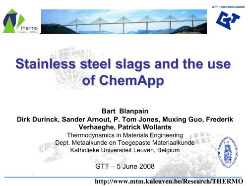
Stainless steel slags and the use of ChemApp - RWTH Aachen ...
Stainless steel slags and the use of ChemApp - RWTH Aachen ...
Stainless steel slags and the use of ChemApp - RWTH Aachen ...

Create successful ePaper yourself
Turn your PDF publications into a flip-book with our unique Google optimized e-Paper software.
<strong>Stainless</strong> <strong>steel</strong> <strong>slags</strong> <strong>and</strong> <strong>the</strong> <strong>use</strong><br />
<strong>of</strong> <strong>ChemApp</strong><br />
Bart Blanpain<br />
Dirk Durinck, S<strong>and</strong>er Arnout, P. Tom Jones, Muxing Guo, Frederik<br />
Verhaeghe, Patrick Wollants<br />
Thermodynamics in Materials Engineering<br />
Dept. Metaalkunde en Toegepaste Materiaalkunde<br />
Katholieke Universiteit Leuven, Belgium<br />
GTT – 5 June 2008<br />
http://www.mtm.kuleuven.be/Research/THERMO
Introduction<br />
Outline<br />
EAF process in stainless <strong>steel</strong> production<br />
Slag stabilisation <strong>and</strong> microstructure calculation
Katholieke Universiteit Leuven
Thermodynamics<br />
in<br />
Materials Engineering<br />
Research Group<br />
Department<br />
<strong>of</strong><br />
Metallurgy <strong>and</strong> Materials Engineering
I. Pyrometallurgical processing<br />
Vessel integrity<br />
Slag practice <strong>and</strong><br />
properties<br />
Steel cleanliness<br />
Modelling
Centre for high temperature processes,<br />
metallurgy <strong>and</strong> refractory materials<br />
Cooperation with industrial partners active in<br />
high temperature metals processing:<br />
ArcelorMittal, Heraeus Electro-Nite <strong>and</strong> Umicore<br />
Fly wheel function for intense collaboration<br />
through substantial research projects <strong>and</strong><br />
doctoral research programs
II. Phase relations in materials systems<br />
Determination <strong>and</strong><br />
optimisation <strong>of</strong> phase<br />
diagrams in metallic<br />
systems<br />
Phase relations in slag<br />
systems<br />
Thermodynamics <strong>of</strong><br />
nanomaterials systems<br />
Sp K<br />
Fe Ti<br />
Fe<br />
Al<br />
Fe<br />
Ni<br />
Bcc phases in th<br />
ternary Al-Fe-N<br />
sub-systems
III. Microstructure evolution modelling<br />
Grain growth<br />
Lead-free solder systems<br />
Dissolution <strong>of</strong> ferro-alloys in liquid <strong>steel</strong><br />
Solidification <strong>of</strong> <strong>slags</strong>
<strong>Stainless</strong> <strong>steel</strong> <strong>slags</strong>
Steel production sites in Belgium
Steel production sites in Belgium
<strong>Stainless</strong> <strong>steel</strong> <strong>slags</strong><br />
General<br />
- By-product/waste <strong>of</strong> stainless <strong>steel</strong> production<br />
- Metallurgical functions:<br />
* Oxidation shielding<br />
* Impurity removal<br />
* Thermal insulation<br />
Amounts<br />
- Slag-to-<strong>steel</strong> ratio: 275 kg slag / 1000 kg <strong>steel</strong><br />
- Global stainless <strong>steel</strong> production: 25 Mt <strong>steel</strong><br />
(source: ISSF,IISI)<br />
~ 7 Mt stainless <strong>steel</strong> slag / year
Assumptions: density = 2.5 ton/m³, Gizeh pyramid dimensions = 230m.230m.137m
World <strong>steel</strong> production: ~ 1.25•10 9 tons<br />
Slag/<strong>steel</strong> ratio: 1/3 ~ 1/4<br />
World iron <strong>and</strong> <strong>steel</strong> slag production: ~ 350•10 6 tons<br />
Assumptions: density = 2.5 ton/m³, Gizeh pyramid dimensions = 230m.230m.137m
<strong>Stainless</strong> <strong>steel</strong> production<br />
3-step process (before casting)<br />
- EAF: scrap melting<br />
- AOD/VOD: de-C <strong>and</strong> de-S<br />
- Ladle refining: de-S<br />
EAF slag<br />
125 kg/ton <strong>steel</strong><br />
De-C slag<br />
180 kg/ton <strong>steel</strong><br />
Ladle slag<br />
20 kg/ton <strong>steel</strong>
<strong>Stainless</strong> <strong>steel</strong><br />
EAF <strong>slags</strong><br />
<strong>Stainless</strong> <strong>steel</strong><br />
De-C <strong>slags</strong><br />
<strong>Stainless</strong> <strong>steel</strong><br />
ladle <strong>slags</strong><br />
Overview slag compositions<br />
Motz <strong>and</strong> Kuhn., Scanmet II, 2004
Process Modelling:<br />
Chromium recovery<br />
<strong>and</strong> foaming in <strong>the</strong> EAF<br />
S. Arnout, F. Verhaeghe, B. Blanpain, P. Wollants, R. Hendrickx, G. Heylen,, Steel<br />
Research International, 77 (5) (2006), 317 - 323<br />
S. Arnout, D. Durinck, M. Guo. B. Blanpain, P. Wollants, J. American Ceramic Society, 91<br />
(2008) 1237-1243<br />
M.X. Guo, D. Durinck, P.T. Jones, G. Heylen, R. Hendrickx, R. Baeten, B. Blanpain, P.<br />
Wollants, Steel Research International, 78 (2) (2007), 117 - 124<br />
D. Durinck, P.T. Jones, M.X. Guo, F. Verhaeghe, G. Heylen, R. Hendrickx, R. Baeten, B.<br />
Blanpain, P. Wollants, Steel Research International, 78 (2) (2007), 125 – 135
Slag in <strong>the</strong> EAF
The EAF process<br />
Slag issues during EAF refining<br />
Early liquid slag formation prevent over-oxidation<br />
<strong>of</strong> Cr<br />
Slag foaming increase furnace productivity,<br />
refractory lifetime, energy <strong>and</strong> material efficiency<br />
Chromium recovery economical & environmental<br />
reasons<br />
Immobilisation <strong>of</strong> CrO x enhance slag valorisation<br />
potential<br />
All affected by high-T slag microstructure
Two distinct 120t EAFs<br />
Furnace types<br />
EAF1 = Eccentric Bottom Tapping Furnace<br />
No C/O 2 lance no foaming<br />
EAF2 = Spout Tapping Furnace<br />
C/O 2 lance slag foaming<br />
EAF1 (EBTF) EAF2 (STF)
EAF operations
Raw data<br />
Selection<br />
Heat Data<br />
Reconciliation<br />
Total weights<br />
<strong>of</strong> additions<br />
Mass additions<br />
times<br />
Time evolution<br />
energy input<br />
Dynamic model<br />
Input:<br />
Scrap<br />
Fluxes<br />
Oxygen<br />
...<br />
Equilibrium 1<br />
Equilibrium 2<br />
Equilibrium 3<br />
...<br />
Equilibrium n<br />
Output 1 = Input 2<br />
Output 2 = Input 3<br />
Output<br />
Efficiency<br />
Energy loss<br />
Energyinput
Temperature evolution
Steel composition
Slag composition
Phases in <strong>the</strong> slag
Slag Sampling<br />
Schematic diagram <strong>of</strong> EAF process (STF) <strong>and</strong> sampling moments
Results – Evolution slag composition<br />
Evolution in STF-slag composition:<br />
(C+M)/S (basicity) decreases during process (FeSi additions for Crrecovery)<br />
FeO drops significantly<br />
CrO x mainly drops during tapping<br />
Evolution in EBTF-slag composition:<br />
Higher final CrO x levels due to tapping procedure<br />
Observed range <strong>of</strong> global slag composition during STF-process
Results – Final CrO x values (tapping)<br />
Difference in Cr recovery due to tapping procedure<br />
EBTF: poor mixing<br />
STF: excellent mixing<br />
Evolution ‘Cr 2 O 3 ’ level (global slag composition) during STF-process<br />
EBTF tapping:<br />
first <strong>steel</strong>, <strong>the</strong>n<br />
slag, poor mixing<br />
in transfer ladle<br />
STF tapping: first slag,<br />
<strong>the</strong>n <strong>steel</strong>, good mixing<br />
in transfer ladle
Slag microstructure<br />
Metal droplet<br />
Spinel particle<br />
Slag matrix
Results – Evolution slag microstructure<br />
STF – Before blowing<br />
(bar = 250 µm)<br />
STF – After blowing<br />
(bar = 250 µm)<br />
Process time<br />
STF – After tapping<br />
(bar = 250 µm)
Slag microstructure – metal droplets<br />
Type 1: large (>50 µm): stainless<br />
<strong>steel</strong> particles (originating from <strong>steel</strong><br />
bath)<br />
Type 2: small (< 5 µm)<br />
Type 2a (25%): stainless <strong>steel</strong><br />
composition<br />
Type 2b (75%): Fe/Cr (no Ni) from<br />
two reactions:<br />
FeO slag (l) + CO(g) = Fe(l) + CO 2 (g)<br />
CrO x,slag (l) + x.CO(g) = Cr Fe (l) + x.CO 2 (g)<br />
Composition metallic droplets in <strong>the</strong> slag
Slag microstructure – spinel particles<br />
Size: ~20 µm, shape: angular<br />
Present at high temperature<br />
Composition: (Mg,Fe,Mn)O.(Cr,Al) 2 O 3<br />
Evolution in composition (see table)<br />
Amount <strong>of</strong> particles decreases with process time (~ FeSi<br />
addition & Cr-recovery)<br />
STF-samples after tapping: almost no particles left<br />
Compositional evolution spinel particles during STF-process<br />
Sample Cr 3+<br />
Al 3+ Mg 2+<br />
Fe 2+ Mn 2+<br />
Ca 2+ M 3+ /M 2+<br />
448032 A 25.0 2.6 6.4 5.9 1.8 0.9 1.8<br />
448032 B 25.0 2.7 7.4 2.2 2.9 1.4 2.0<br />
448032 C 24.9 3.6 8.3 0.8 3.4 0.9 2.1<br />
448032 D 24.9 3.5 9.2 1.1 2.5 0.9 2.1<br />
448032 E 19.5 6.3 12.3 0.3 1.6 0.7 1.8<br />
Spinel particles in slag<br />
(bar = 100 µm)
Slag microstructure – spinel particles<br />
Formation <strong>and</strong> dissolution <strong>of</strong><br />
spinel particles controlled by:<br />
Cr 2 O 3 /Al 2 O 3 (l) + MgO (l) <br />
MgO.(Cr,Al) 2 O 3 (s)<br />
Equilibrium influenced by T, pO 2<br />
(influences CrO/Cr 2 O 3 level) ,<br />
C+M/S, CrO x <strong>and</strong> MgO level<br />
FactSage 5.2 + Chemapp<br />
V5.1.6 qualitative phase<br />
diagram<br />
Process evolution shown by<br />
arrow: from L/spinel L region<br />
without spinel Qualitative phase diagram: C/S, p, p O2 <strong>and</strong> T are<br />
kept constant
Results: liquidus<br />
Tests in different known p O2 , no Al 2 O 3<br />
T=1600°C<br />
p O2 =10 -10.16 atm<br />
B=1.2
Results: liquidus<br />
Tests in known p O2 , changing Al 2 O 3<br />
T=1600°C<br />
p O2 =10 -9.36 atm<br />
B=1.2
O<strong>the</strong>r examples <strong>of</strong> process modelling<br />
VOD stainless <strong>steel</strong> refining<br />
S. Smets et al., unpublished.<br />
Zinc fuming (including freeze lining formation)<br />
Cooperation with E. Jak <strong>and</strong> P. Hayes<br />
K. Verscheure et al., Met. Trans. B, 38B (2007), 13 – 33<br />
Lead Blast Furnace<br />
Cooperation with E. Jak <strong>and</strong> P. Hayes<br />
F. Verhaeghe et al., Proc. CSIRO, 4th Australian Melt Chemistry<br />
Symposium , 10-11 December 2002<br />
Exergy analysis <strong>of</strong> pyrometallurgical processes<br />
B. Klaasen et al, master <strong>the</strong>sis K.U.Leuven, 2008 (in dutch)
Slag Valorisation:<br />
<strong>the</strong> importance <strong>of</strong> microstructure<br />
Roadways to a stable slag product<br />
D. Durinck, S. Arnout, G. Mertens, E. Boydens, P.T. Jones, J. Elsen, B. Blanpain, P. Wollants,<br />
JOURNAL OF THE AMERICAN CERAMIC SOCIETY 91(2008) 548-554<br />
D. Durinck, P.T. Jones, B. Blanpain, P. Wollants, G. Mertens, J. Elsen, Journal <strong>of</strong> The<br />
American Ceramic Society, 90 (4) (2007), 1177 - 1185
Dumping<br />
Valorisation
Slag valorisation chain
Slow slag solidification<br />
24 h
Main applications:<br />
Slag valorisation chain<br />
- Flemish environmental law:<br />
“aggregates within o<strong>the</strong>r<br />
products”<br />
Concretes<br />
- Cementitious concrete<br />
- Asphalt concrete
Slag valorisation chain<br />
Required slag properties for aggregate for asphalt concrete:<br />
- Particle size > 2 mm<br />
- Resistance against polishing<br />
- Abrasion resistance<br />
- Strength<br />
- Cr leaching<br />
- Volume stability
1,2<br />
Slag composition<br />
‘CaO’ SiO 2 MgO Al 2 O 3 Amount<br />
wt%<br />
Ton slag/100 ton <strong>steel</strong><br />
DS1 40 26 7 9 6<br />
DS2 40 30 11 9 7<br />
AOD 51 34 11 1 8<br />
VOD 51 34 11 1 5<br />
FS/CC 64 21 9 1 2<br />
3,4<br />
5<br />
6<br />
7
EAF = Al 2 O 3 containing<br />
Slag composition
EAF = Al 2 O 3 containing<br />
Slag composition<br />
CaF 2 <strong>and</strong> CaS<br />
measured as CaO
Slag disintegration<br />
FS/CC slag after cooling: Too fine to valorise<br />
Lab simulation
Slag disintegration<br />
Visual observation at <strong>the</strong> slag yard
Ca<strong>use</strong> <strong>of</strong> slag disintegration<br />
Presence <strong>of</strong> 2CaO.SiO 2 (C 2 S)<br />
- several phase transformations during<br />
cooling<br />
- β to γ transformation ca<strong>use</strong>s a 12%<br />
volume expansion<br />
Chan et al., J. Am. Cer. Soc., 1992 Kim et al., J. Am. Cer. Soc., 1992
Internal slag recycling<br />
What can be done?<br />
Benefits: Ca resource, fluxing agent, possible heat source<br />
Problems: Logistics (dry slag required / molten slag addition)<br />
Physical slag stabilisation<br />
Grain size<br />
Matrix constraint<br />
Cooling rate<br />
Chemical slag stabilisation<br />
Stabilise β-C 2S to room temperature by doping
Laboratory experiment<br />
Slag composition Cooling path<br />
CaO-SiO 2-MgO<br />
• Well known system<br />
•p O2 independent<br />
• <strong>Stainless</strong> <strong>steel</strong>making slag<br />
• Peritectic reaction<br />
Cooling rate 1°C/min<br />
• Simple cooling path<br />
• Used in o<strong>the</strong>r references<br />
• Comparable to industry<br />
(not equal!)
Common approaches to solidification<br />
modelling<br />
Diffusion rate in liquid<br />
∞<br />
X<br />
0<br />
Scheil-Gulliver<br />
Diffusion controlled<br />
0 ∞<br />
Diffusion rates in solids<br />
Thermodynamic<br />
equilibrium
Assumptions<br />
Thermodynamic equilibrium model<br />
• Equilibrium @ L/S interface<br />
• Infinitely rapid diffusion in L<br />
• Infinitely rapid diffusion in S<br />
f<br />
Amount <strong>of</strong> A:<br />
s,<br />
equil<br />
=<br />
a<br />
i<br />
bi<br />
+<br />
b<br />
i<br />
T 1<br />
A B<br />
> T 2<br />
> T 3<br />
> T 4
Assumptions<br />
• Equilibrium @ L/S interface<br />
• Infinitely rapid diffusion in L<br />
• No diffusion in S<br />
f<br />
Amount <strong>of</strong> A:<br />
bi<br />
=<br />
a + b<br />
s,<br />
SG<br />
∑<br />
i= 1→N<br />
i i<br />
Scheil-Gulliver model<br />
T 1<br />
A B<br />
> T 2<br />
> T 3<br />
> T 4
Mineralogy<br />
Experiment Equilibrium Scheil-Gulliver<br />
L + M + C 2 S C 3 MS 2
Microstructure<br />
Syn<strong>the</strong>tic<br />
Industrial With B2O3 With B2O31460°C L + M + C 2 S C 3 MS 2<br />
2.C 2 S + C 3 MS 2 C 7 MS 4
Air-cooled solidification<br />
pO 2 independent systems (i.e. CaO-MgO-SiO 2 )<br />
Scheil-solidification model<br />
Lab experiments + QXRD<br />
Validated with industrial samples
Air-cooled solidification<br />
Preliminary results<br />
CS<br />
C 2 S<br />
Cr 2 O 3<br />
C 3 K 2 S 3<br />
Cr
Microstructural calculations<br />
CaO-SiO 2 -MgO-CrO x model system – pO 2<br />
dependent<br />
D. Durinck et al., J. Am. Cer. Soc., accepted<br />
Description <strong>of</strong> <strong>the</strong> formation <strong>of</strong> freeze lining<br />
systems<br />
Cooperation with E. Jak <strong>and</strong> P. Hayes<br />
M. Campforts et al., Met. Trans. B. , 38B(2007)6,<br />
p.841-851<br />
Phase field modelling for <strong>the</strong> solidification <strong>of</strong><br />
oxide systems<br />
Cooperation with GTT <strong>and</strong> Access<br />
J. Heulens <strong>and</strong> N. Moelans
Conclusions<br />
Basic research tools in high temperature<br />
metallurgical research<br />
Thermodynamic modeling (<strong>ChemApp</strong> <strong>and</strong> FactSage)<br />
• Process modelling<br />
• Microstructure calculations<br />
Laboratory <strong>and</strong> industrial experiments<br />
Microstructural <strong>and</strong> (micro-)analytical characterization