Some aspects of safe-life and damage tolerant design of railway axles
Some aspects of safe-life and damage tolerant design of railway axles
Some aspects of safe-life and damage tolerant design of railway axles

You also want an ePaper? Increase the reach of your titles
YUMPU automatically turns print PDFs into web optimized ePapers that Google loves.
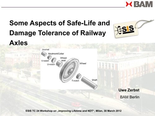
<strong>Some</strong> Aspects <strong>of</strong> Safe-Life <strong>and</strong><br />
Damage Tolerance <strong>of</strong> Railway<br />
Axles<br />
ESIS TC 24 Workshop on „Improving Lifetime <strong>and</strong> NDT“, Milan, 30 March 2012<br />
Uwe Zerbst<br />
BAM Berlin
Axle fracture ICE3, 9 July 2008<br />
Press photo<br />
ICE 518, Hohenzollern Bridge<br />
Fracture after 10 9 loading cycles<br />
Expert‘s report (BAM)<br />
Cause: non-metallic inclusions<br />
in the highly stressed volume?<br />
Source: ARD, Monitor<br />
2008-11-06
Design <strong>and</strong> operation: Safety levels<br />
State-<strong>of</strong>-the-art
Primary (Basic) Safety Level<br />
Present state: Quasi-static <strong>design</strong><br />
- dynamic magnification factors<br />
- synchrone loading<br />
- Safety margins for VHCF etc.<br />
- Corrosion: Reduction <strong>of</strong> stress level to 70% (EN 13261)
Effect <strong>of</strong> corrosion<br />
Effect <strong>of</strong> corrosion medium<br />
(rain water) on S-N curve<br />
Beretta et al.;<br />
Polimi Mail<strong>and</strong>, 2010<br />
Dramatic Limitation <strong>of</strong> Service Time<br />
or<br />
Protection<br />
Measures<br />
LURSAK ®
Basic Safety Level<br />
Present state: Quasi-static <strong>design</strong><br />
- dynamic magnification factors<br />
- synchrone loading<br />
- Safety margins for VHCF etc.<br />
- Corrosion: Reduction <strong>of</strong> stress level to 70% (EN 13261)<br />
Proposals: Damage accumulation <strong>design</strong> (Eisenbahnfahrwerke 1; WIDEM; etc.)<br />
- different approaches<br />
- classified load spectra necessary
Does load accumulation<br />
„cover“ VHCF?<br />
Concepts for Fatigue<br />
Strength Design<br />
VHCF<br />
Beretta et al.
Basic Safety Level<br />
Present state: Quasi-static <strong>design</strong><br />
- dynamic magnification factors<br />
- synchrone loading<br />
- Safety margins for VHCF etc.<br />
- Corrosion: Reduction <strong>of</strong> stress level to 70% (EN 13261)<br />
Proposals: Damage accumulation <strong>design</strong> (Eisenbahnfahrwerke 1; WIDEM; etc.)<br />
- different approaches<br />
- classified load load spectra necessary<br />
„One million miles axle“ (A. Lawton, 2003; WIDEM)<br />
- Design such, that 10 9 LC realised under most<br />
disadvantageous conditions<br />
- Inclusion <strong>of</strong> fracture mechanics
Conventional S-N Curve <strong>and</strong> S-N Curve Based<br />
on Fracture Mechanics<br />
(Initial Crack depth: 2 mm)<br />
Beretta et al.
Factors, which reduce fatigue strength<br />
during service (1)<br />
Service conditions Max. Corrosion pit depth in in mm<br />
Relatively well protected against<br />
corrosion<br />
Corrosion typical or a bit more<br />
severe than typical<br />
Significantly more severe (wagon<br />
carrying corrosion freight<br />
Korrosionseinfluss<br />
* British Rail Safety <strong>and</strong> St<strong>and</strong>ards Board<br />
TWI<br />
0.043<br />
0.076<br />
0.346<br />
Estimated<br />
maximum<br />
(1 axle)<br />
0.1<br />
0.24<br />
0.82<br />
Beretta et al.<br />
Estijmated<br />
maximum<br />
(fleet)<br />
0.13<br />
0.35<br />
1.02<br />
Corrosion pits<br />
(mainly freight wagons)<br />
T278 Projekt <strong>of</strong><br />
BRSSB*<br />
Watson
Factors, which reduce fatigue strength<br />
during service (2)<br />
Failure case Australia 2007<br />
Beretta et al.<br />
T278 Projekt <strong>of</strong> BRSSB:<br />
Average depth: 0,8 mm<br />
95% Maximum depth: 2 mm<br />
Stress concentration<br />
(Ceril et al. 2009)<br />
for a/c = 1 K t = 2.15<br />
However:<br />
Flying ballast impacts<br />
(above all high speed traffic)<br />
- Complex residual stress field<br />
- Cracks at notch root?<br />
- Combination with corrosion<br />
K<br />
t<br />
<br />
<br />
1 6.6 a 2c<br />
<br />
1 2 a 2c<br />
With respect to corrosion <strong>and</strong> ballast<br />
impacts protection measures possible
Optimised Geometry:<br />
Berlin 1940s<br />
based on fatigue<br />
<strong>life</strong> experiments<br />
K which, by its nature, not a stress concentration<br />
but kind <strong>of</strong> a fatigue notch factor, although reciprocally<br />
proportional to the usual definition, i.e., K > 1<br />
Depends not only on the notch geometry but also on<br />
material<br />
Empirically derived for A1 steel (UIC Leaflet 881-V,<br />
1979); tensile strength between 550 <strong>and</strong> 650 MPa<br />
K solutions cannot be simply applied to higher<br />
strength <strong>railway</strong> axle steels<br />
Note further: stress state at the geometrical transitions<br />
not only influenced by applied loading <strong>and</strong> notch geo-<br />
metry but also by the press fits (additional axial tensile<br />
stresses adjacent to the press seat regions)<br />
More fundamental investigation is necessary<br />
for deviating geometries:<br />
EN 13103 <strong>and</strong> EN 13104
Loading <strong>of</strong> an Axle<br />
Static <strong>and</strong> dynamic axle loads<br />
Bending <strong>and</strong> axial tension at curved<br />
track sections, crossovers <strong>and</strong><br />
switches<br />
Torsion during traction <strong>and</strong> braking,<br />
Higher frequency loading due to<br />
stick-slip behaviour<br />
Press fit loading<br />
Residual stresses<br />
from manu-<br />
facturing<br />
Hirakawa et al., 1998<br />
Madia et al., 2008
Problem: non-metallic Inclusions<br />
ICE3 axle <strong>of</strong> Köln<br />
Failure investigations: BAM<br />
C. Klinger et al.<br />
ultrasonic immersion technique
Non-metallic<br />
Inclusions:<br />
Origin in<br />
Manufacturing<br />
Process<br />
Effect on Lifetime:<br />
C-Steel; Ma et al., 2010
Non-metallic inclusions<br />
Allowed maximum depth(EN 13261 referring to ISO 4967)<br />
Verification: metallographic; requirerd test area min. 200 mm 2<br />
no specification on sampling volume<br />
Problem: Inclusions <strong>of</strong> critical size at critical position<br />
rather seldom.<br />
Statistics <strong>of</strong> European Railway Agency for the EU 2006 - 2009:<br />
- 1 fracture event per 2 Billions axle kilometers<br />
- also other mechanicsm than fatigue (e.g., hot box failure)<br />
It is certainly inconsistent to look for seldom events by a very limited sample!
Proposal:<br />
Establish as-is state <strong>of</strong> inclusions<br />
Establish NDT method (e.g. US immersion<br />
technique for throughout detection <strong>of</strong> inclusions<br />
above a certain size<br />
Realistic (limit) size: 0.5 mm?<br />
(relevant: Inclusion dimensions normal to axle)<br />
Inclusions smaller than those found by NDT assumed as existent<br />
Establish correction factor for fatigue strength
Design <strong>and</strong> operation: Safety levels
Secondary Safety Level<br />
PoD = probability <strong>of</strong> detection
Inspektion interval<br />
Aim: Economically justifiable inspektion interval combined with a high probability<br />
for crack detection (PoD)<br />
Non-detection probability (PoND) corresponds with probability that a potential<br />
crack will be found in due time bevor the axle fails<br />
Parameters affecting overall PoD:<br />
<br />
PODoverall 1PONDi i <br />
- Inspektion interval (respectively number <strong>of</strong> inspections)<br />
- Residual <strong>life</strong>time (Fracture mechanics analysis)<br />
- PoD-crack depth-characteristics (NDT)<br />
i = i-th inspection
Potential Margins with<br />
Respect to Inspektion<br />
intervals<br />
Improved Fracture mechanics<br />
analysis, particularly in the threshold<br />
range (S)<br />
Variable amplitude loading<br />
- Both not unproblematic<br />
- Effect rather small (?)
Problem: Threshold region <strong>of</strong><br />
Fatigue crack propagation DK th
Potential Margins with<br />
Respect to Inspektion<br />
intervals<br />
Improved Fracture mechanics<br />
analysis, particularly in the threshold<br />
range (S)<br />
Variable amplitude loading<br />
- Both not unproblematic<br />
- Effect rather small (?)<br />
Improvement <strong>of</strong> POD<br />
Results: WIDEM (manual testing)
Potential for Improvement <strong>of</strong> the PoD (1)<br />
Interpretation <strong>of</strong> A-scans instead <strong>of</strong> gate mode technique<br />
Optimisation <strong>of</strong> angle <strong>of</strong> incidence with respect to geometry<br />
(Phased Array Technik)<br />
Advanced methods such as echo tomograpgy, SAFT, etc.<br />
Regions <strong>of</strong> increased danger: generally „Analyseprüfung“<br />
However: limited time for a test as a second essential goal<br />
Validation <strong>and</strong> calibration <strong>of</strong> test equipment for real cracks!
Potential for Improvement <strong>of</strong> the PoD (2)<br />
Caution: real cracks behalf<br />
different to saw cuts in<br />
ultrasonic testing!
Thanks for your attention<br />
More detailled information:<br />
uwe.zerbst@bam.de