Code of practice for overhauling of dc motors with anti-friction/sliding ...
Code of practice for overhauling of dc motors with anti-friction/sliding ...
Code of practice for overhauling of dc motors with anti-friction/sliding ...

You also want an ePaper? Increase the reach of your titles
YUMPU automatically turns print PDFs into web optimized ePapers that Google loves.
IPSS<br />
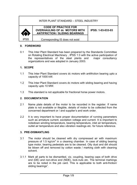
0. FOREWORD<br />
INTER PLANT STANDARD – STEEL INDUSTRY<br />
CODE OF PRACTICE FOR<br />
OVERHAULING OF <strong>dc</strong> MOTORS WITH<br />
ANTIFRICTION / SLIDING BEARINGS<br />
Corresponding IS does not exist<br />
IPSS: 1-03-033-03<br />
0.1 This Inter Plant Standard has been prepared by the Standards Committee<br />
on Rotating Electrical Machinery , IPSS 1:3 <strong>with</strong> the active participation <strong>of</strong><br />
the representatives <strong>of</strong> the steel plants and major consultancy<br />
organizations and was adopted in January 2003.<br />
1. SCOPE<br />
1.1 This Inter Plant Standard covers <strong>dc</strong> <strong>motors</strong> <strong>with</strong> <strong>anti</strong><strong>friction</strong> bearing upto a<br />
capacity <strong>of</strong> 1000 kW.<br />
1.2 This Inter Plant Standard covers <strong>dc</strong> <strong>motors</strong> <strong>with</strong> <strong>sliding</strong> bearing and having<br />
capacity upto 10 MW.<br />
1.3 This standard is not applicable <strong>for</strong> fractional horse power <strong>motors</strong>.<br />
2. DOCUMENTATION<br />
2.1 Name plate details <strong>of</strong> the motor to be recorded in the register. If name<br />
plate is not available or illegible, details <strong>of</strong> motor to be collected from the<br />
concerned department or / and supplier’s and work order.<br />
2.2 It is very important to have proper documentation <strong>of</strong> running parameters<br />
such as armature current, excitation voltage and current. It is important to<br />
notedown winding temperature, bearing temperature, inlet air temperature,<br />
outlet air temperature and also vibration readings etc. <strong>for</strong> future reference.<br />
3. PRE-DISMANTLING<br />
3.1 The motor should be cleaned <strong>with</strong> dry compressed air <strong>with</strong> maximum<br />
pressure <strong>of</strong> 1.5 kg/cm 2 in a cleaning chamber. In case <strong>of</strong> <strong>sliding</strong> bearing<br />
type motor, bearing pedestals are to be cleaned. Oily dust and dirt should<br />
be blown <strong>of</strong>f and removed by cotton waste / marking cloth <strong>with</strong> cleaning<br />
solvent.<br />
3.1.1 Mark all parts to be dismantled, viz, coupling, bearing caps <strong>of</strong> both drive<br />
end (DE) and non-drive end (NDE), lock-nuts etc. The terminal markings<br />
are to be noted in the job card. This is applicable to both <strong>anti</strong>-<strong>friction</strong>/<br />
<strong>sliding</strong> bearings”.<br />
Page 1/9
IPSS:1-03-033-03<br />
3.2 In case <strong>of</strong> <strong>sliding</strong> bearing type motor, visual inspection and proper marking<br />
<strong>of</strong> all external parts in addition to clause 3.1.1 including oil pipe line<br />
connections and thermometer installation should be done. Also take<br />
bearing clearance wherever possible. The pre movement <strong>of</strong> oil ring may<br />
be checked be<strong>for</strong>e dismantling.<br />
3.3 Check the IR value <strong>of</strong> the armature, IP and compensating winding and<br />
field circuit and record the readings. Wherever insulated bearing are there,<br />
they should be meggered and values recorded.<br />
3.4 Make a physical inspection in respect <strong>of</strong> the following and prepare a<br />
defect list prior to dismantling.<br />
3.4.1 Take the beating <strong>of</strong> coupling shaft.<br />
3.4.2 Check the condition <strong>of</strong> brushes w.r.t. its remaining wearing depth,<br />
condition <strong>of</strong> pigtails, carbon brush holders, brush boxes, tension adjustors,<br />
etc.<br />
3.4.3 Note the condition <strong>of</strong> the shaft, fan, fan cover, foundation legs, terminal<br />
board and terminals.<br />
3.4.4 Check the air gap between main pole and armature.<br />
3.4.5 Make a physical and schematic diagram <strong>of</strong> connection <strong>of</strong> armature,<br />
interpole, compensating winding, main pole coils.<br />
Make a sketch <strong>of</strong> terminal board connections and their markings.<br />
3.5 On the basis <strong>of</strong> above pre dismantling inspection/ checking, prepare a<br />
consolidated defect list to take up necessary rectification during<br />
<strong>overhauling</strong>.<br />
4. DISMANTLING<br />
4.1 General<br />
4.1.1 Remove ventilation system i.e. blower, ventilation duct, if any. Disconnect<br />
the connections at the terminal board, brush holder arms, rocker<br />
assembly, etc after marking suitable identifying marks on the parts which<br />
are connected electrically i.e. bus bars/cables and are to be disconnected.<br />
4.1.2 Proper identifying marks are put on all the parts to be dismantled so that<br />
the respective parts could be assembled as per the original assembly after<br />
repair.<br />
Page 2 <strong>of</strong> 9
IPSS:1-03-033-03<br />
4.1.3 The dismantling is to be carried out as per the following procedure :<br />
- Take out the coupling <strong>with</strong> the help <strong>of</strong> a hydraulic puller. In some cases<br />
heating may be required. Care is to be taken not to overheat. Inspect the<br />
shaft surface, bore <strong>of</strong> coupling, key/keyway <strong>for</strong> any marks <strong>of</strong> wear &<br />
de<strong>for</strong>mation.<br />
- Open top / bottom half fixing bolts along <strong>with</strong> bearing cartridge bolts to<br />
falcilitate removal <strong>of</strong> top half <strong>of</strong> the motor field body. (This is required <strong>for</strong> split<br />
frame <strong>dc</strong> <strong>motors</strong>). The armature then is lifted up from the bottom half and<br />
placed on work bench.<br />
- In the case <strong>of</strong> a non-split construction, the armature is required to be threaded<br />
out after dismantling the end shields on both sides.<br />
4.2 Dismantling <strong>of</strong> motor <strong>with</strong> <strong>anti</strong>-<strong>friction</strong> bearings.<br />
4.2.1 Remove ventilation system i.e. blower, ventilation duct, if any. Disconnect<br />
the connections at the terminal board, brush holder arms, rocker<br />
assembly, etc after marking suitable identifying marks on the parts which<br />
are connected electrically i.e. bus bars/cables and are to be disconnected.<br />
4.2.2 In case <strong>of</strong> non-split construction, the armature is to be threaded out.<br />
Follow the instructions <strong>for</strong> dismantling <strong>of</strong> the motor as supplied by the<br />
machine manufacturer”.<br />
4.2.3 Wherever field system is in two halves, mark properly the interpole<br />
connections, current collecting half bus bars and rocker assembly position<br />
be<strong>for</strong>e taking them out.<br />
4.2.4 Open the bearing and take out the top covers. Put proper identification.<br />
Take out top half <strong>of</strong> the bearing (if the bearing is in two halves, after<br />
marking properly). Take out labyrinths from both ends <strong>of</strong> the bearings.<br />
4.2.5 In case <strong>of</strong> large <strong>motors</strong>, sufficient room is normally not available <strong>for</strong><br />
threading out <strong>of</strong> the armature from the field body (non-split type) at the<br />
drive location. In this case, both armature and the stator body is to be<br />
taken out from its position and shifted to a place where EOT crane is<br />
available.<br />
4.2.5.1 Threading out <strong>of</strong> the armature is to be done after removing the<br />
motor/generator to a place where the stools have been prepared<br />
be<strong>for</strong>e hand. Depending upon the situation, either the field body or the<br />
armature can be threaded out. Use <strong>of</strong> balance beam which facilitates<br />
easy thread out should be preferred. S<strong>of</strong>t gasket may be inserted in<br />
the air gap to avoid damage to core/winding.<br />
4.2.6 In case <strong>of</strong> non-split construction, the armature is to be threaded out. S<strong>of</strong>t<br />
gasket may be inserted in the air gap to avoid damage to coir/winding.<br />
Page 3 <strong>of</strong> 9
IPSS:1-03-033-03<br />
4.2.7 In the case <strong>of</strong> split type <strong>of</strong> field body the top half and the armature is lifted<br />
one after the another and placed in suitable location <strong>for</strong> further jobs. The<br />
top half should be suitably placed so that access to cleaning/repairing is<br />
available.<br />
4.3 Dismantling <strong>of</strong> <strong>motors</strong> <strong>with</strong> <strong>sliding</strong> bearings<br />
4.3.1 Remove thermometer and oil pipeline connection to <strong>sliding</strong> bearings.<br />
5. POST-DISMANTLING CHECKS AND REPAIRS - Clean the armature and<br />
field thoroughly, first by blowing <strong>with</strong> dry and clean compressed air & suitable<br />
cleaning agent or putting under vaccum where such facility exists, and then<br />
<strong>with</strong> a suitable cleaning agent to remove dust, oil and grease. In the mean<br />
time, look <strong>for</strong> any abnormality both in the armature as well as in the field<br />
body, viz, broken/missing wedges, dry solders in risers, looseness in banding,<br />
cracks in armature equalizer connections, cracks in insulators, etc and rectify.<br />
Minor repairs <strong>of</strong> these nature is to be done be<strong>for</strong>e it is put to oven / heat<br />
chamber <strong>for</strong> drying. If it is possible, it should be allowed to dry in furnace <strong>for</strong> a<br />
required duration to stabalize desired IR value at the specified temperature as<br />
per class <strong>of</strong> insulation. In case the dirt is too much, sometimes it is preferred<br />
to heat the armature & field be<strong>for</strong>e actual cleaning <strong>of</strong> armature upto a safe<br />
value is done.<br />
5.1 Armature<br />
5.1.1 Take the beating <strong>of</strong> coupling shaft.<br />
5.1.2 Carry out mica undercutting and bevelling <strong>of</strong> commutator.<br />
5.1.3 Carry out DROP TEST on commutator. If drop across certain pair <strong>of</strong><br />
segments are high (greater than 5%), these are to be resoldered, cleaned<br />
thoroughly & rechecked. If the drop is low (less than 5%) then those<br />
segments are to be thoroughly cleaned by a cleaning agent, dried & redroptested<br />
(Segments showing variation in drop test more than +5% / -5%<br />
upto a maximum limit <strong>of</strong> 5% <strong>of</strong> total commutator bars spread over the<br />
circumference can be allowed).<br />
5.1.4 Check condition <strong>of</strong> wedges, coil insulation and bandages. If the wedges<br />
are bad, it should be changed. If the banding is not proper it should be<br />
replaced. If coils are damaged, repair or replace them. For banding<br />
purpose, resiglass banding tapes may be used <strong>with</strong> suitable no. <strong>of</strong> turns.<br />
Banding tape curing is to be done at a particular temperature & <strong>for</strong> a<br />
specified time as prescribed in the brochure.<br />
5.1.5 Check the Condition <strong>of</strong> Bearings :<br />
5.1.5.1 In case <strong>of</strong> motor <strong>with</strong> <strong>anti</strong><strong>friction</strong> bearing, check the condition <strong>of</strong><br />
bearings and their tightness on shaft. If loose, the damaged bearing<br />
Page 4 <strong>of</strong> 9
IPSS:1-03-033-03<br />
seating should be built up by metallising and machining. Similarly the<br />
coupling seating is to be repaired. This machining job should be<br />
carried out together <strong>with</strong> the turning <strong>of</strong> commutator.<br />
After repair <strong>of</strong> the bearing seating, mount the bearings as per the<br />
original catalogue recommendation.<br />
5.1.5.1.1 Filling and drain out passages in grease cups are to be cleaned and<br />
the old used grease is to be taken out. During cleaning, bearing and<br />
housing is simultaneously cleaned. Thin mineral oil should be used as<br />
solvent and should be pre-heated to around 60-70 o C or as<br />
recommended by the solvent manufacturer. Bearings, grease cups and<br />
accessories to be wiped clean and covered <strong>with</strong> cloth.<br />
5.1.5.1.2 Check proper bearing clearance <strong>with</strong> feeler gauge as per the<br />
procedure laid down in the bearing catalogue.<br />
5.1.5.2 In case <strong>of</strong> motor <strong>with</strong> <strong>sliding</strong> bearing, check the shaft journal condition.<br />
Carry out polishing <strong>of</strong> shaft journal <strong>with</strong> fine emery tapes, if the surface<br />
needs re-dressing. Otherwise <strong>for</strong> finish polishing, use coir rope <strong>for</strong><br />
polishing using fine chalk powder.<br />
Check the conditions <strong>of</strong> oil rings and their ovality. If required, arrange<br />
<strong>for</strong> spare oil rings.<br />
5.1.5.2.1 Check the condition <strong>of</strong> white / babbit metal <strong>of</strong> both halves <strong>of</strong> the<br />
bearings. Touch up <strong>with</strong> a skilled hand, if required, to remove scars on<br />
the bearing surface. Clean oil passages including jacking oil passages<br />
etc.<br />
5.1.5.2.2 Measure the internal diameter <strong>of</strong> the bearing <strong>with</strong> an internal<br />
micrometer by averaging readings taken atleast at 3 places. Note<br />
down the readings.<br />
5.1.6 Measure the IR value, ensure healthiness and take up <strong>for</strong> varnishing<br />
measure IR the armature after ensuring healthy IR. Varnish the armature<br />
<strong>with</strong> a suitable insulating varnish/insulating enamel depending on the class<br />
<strong>of</strong> insulation <strong>of</strong> the machine mentioned in the name plate or brochure.<br />
5.2 Field<br />
5.2.1 Tighten all pole fixing bolts. Tighten all connection bolts. Tighten all<br />
compensating winding and interpole connections. Replace damaged<br />
cables. Check conditions <strong>of</strong> lugs and if required, change the lugs. Anchor<br />
all the inter-connection cables.<br />
In case <strong>of</strong> multipolar machine (except bipolar), pole bore between different<br />
pair <strong>of</strong> segments (main pole & commutating pole) is to be compared &<br />
made as nearly equal as possible.<br />
Page 5 <strong>of</strong> 9
IPSS:1-03-033-03<br />
5.2.2 Check the looseness <strong>of</strong> coils. If necessary, give packing retape coils.<br />
5.2.3 Test the field <strong>for</strong> ensuring correct polarity, equality <strong>of</strong> resistance,<br />
soundness <strong>of</strong> joints etc. Check field winding <strong>for</strong> inter-turn shorts wherever<br />
possible (by surge comparison method).<br />
5.2.4 Varnish the field <strong>with</strong> suitable air drying varnish after insuring healthy IR.<br />
5.3 For Motor <strong>with</strong> Anti<strong>friction</strong> Bearings<br />
5.3.1 End covers shall be checked up <strong>for</strong> their proper fitment and sealing on<br />
bearings. If found loose the covers are to be fitted <strong>with</strong> a metallic sleeve<br />
and machined to size.<br />
5.3.2 If the motor is fitted and sealing <strong>with</strong> bearing capsules, the same operation<br />
as above is to be carried out to ensure proper fitment <strong>of</strong> bearing in the<br />
capsule.<br />
5.4 For Motors <strong>with</strong> Sliding Bearings<br />
5.4.1 Sliding Bearings<br />
5.4.1.1 Check babbit condition and match surfaces <strong>of</strong> lower and upper bushes<br />
<strong>of</strong> babbit bearings. Defective bearings to be replaced and matched.<br />
Bearing gaps and collar clearances to be measured.<br />
5.4.1.2 Ovality de<strong>for</strong>mation and cracks etc to be checked in oil rings.<br />
5.4.1.3 Labyrinths are to be checked and oil grooves, holes are to be cleaned.<br />
5.4.1.4 Rotor journal radial run out is to be checked <strong>for</strong> proper fitting & sealing.<br />
For a shaft diameter <strong>of</strong> 100 to 200 mm, the permissible radial run out<br />
<strong>of</strong> shaft journal is not to exceed 0.02 mm and that <strong>of</strong> a shaft diameter<br />
above 200 mm, it is not to be over 0.03 mm. However, in case <strong>of</strong><br />
working armature having vibration <strong>with</strong>in norm, it could be overlooked.<br />
5.4.1.5 While fitting the bushes <strong>of</strong> journal bearings, shaft journal diameter <strong>with</strong><br />
outside micrometer and the bush hole diameter <strong>with</strong> an internal<br />
micrometer are to be measured. Feeler gauges may be used to<br />
measure the gaps <strong>of</strong> an assembled bearing. The clearance between<br />
shaft journal and the bush must be <strong>with</strong>in norm given in Table-1.<br />
5.4.1.6 Oil sumps are to be cleaned after draining out the used oil. Pedestal<br />
insulation is to be checked. Oil indicating glass and reflectors are to be<br />
cleaned.<br />
Page 6 <strong>of</strong> 9
5.4.2 Other Components<br />
IPSS:1-03-033-03<br />
5.4.2.1 Carry out inspection <strong>of</strong> insulators <strong>of</strong> rocker assembly and defective<br />
insulators to be changed. Current collecting bus bars and insulators<br />
between them should also be checked.<br />
5.5 Spring tension <strong>of</strong> brush holders and condition <strong>of</strong> holder to be checked.<br />
Change wherever necessary.<br />
5.6 Condition <strong>of</strong> ventilation ducts and its connection to be checked.<br />
6. ASSEMBLY<br />
6.1 Motor <strong>with</strong> <strong>anti</strong><strong>friction</strong> bearings – Megger voltage to be specified.<br />
6.1.1 Thread in the armature exactly in reverse order as that followed while<br />
dismantling.<br />
6.1.2 Fit back end shields, grease caps, coupling, etc. Make sure the bearings,<br />
grease cups, etc are filled <strong>with</strong> initial grease (lithium based greases are<br />
preferred <strong>for</strong> <strong>motors</strong>/generators).<br />
6.1.3 Fix back brush rocker arms, position them as accurately as possible as<br />
per the original marking, put carbon brushes into the brush boxes, check<br />
freeness <strong>of</strong> the brush w.r.t. the brush box, bed the brushes so that a<br />
minimum <strong>of</strong> 70% <strong>of</strong> its contact surface is in contact <strong>with</strong> the commutator.<br />
Check the spring tension <strong>of</strong> each carbon brush. This should con<strong>for</strong>m to<br />
carbon brush manufacturer’s recommendation. Ensure that brushes <strong>of</strong><br />
same grade are put back.<br />
6.1.4 Ensure proper connection as per the sketch.<br />
6.1.5 Ensure free rotation <strong>of</strong> armature by rotating armature.<br />
6.1.6 Measure IR value again and record.<br />
6.1.7 Check neutral axis and adjust, if required.<br />
6.2 Motors <strong>with</strong> sleeve bearings.<br />
6.2.1 Thread in armature into the stator exactly in reverse steps as that was<br />
followed while threading out in the case <strong>of</strong> <strong>motors</strong>/generators <strong>with</strong> nonsplit<br />
bearings<br />
6.2.2 For split halved <strong>motors</strong>, place back the armature and the field top half in<br />
reverse sequence as that followed during dismantling. Complete all top<br />
and bottom half connections including carbon brush rocker connections.<br />
Page 7 <strong>of</strong> 9
IPSS:1-03-033-03<br />
6.2.3 Fix back brush rocker arms, position them as accurately as possible as<br />
per the original marking, put carbon brushes into the brush boxes, check<br />
freeness <strong>of</strong> the brush w.r.t. the brush box, bed the brushes so that a<br />
minimum <strong>of</strong> 70% <strong>of</strong> its contact surface is in contact <strong>with</strong> the commutator.<br />
Check the spring tension <strong>of</strong> each carbon brush. This should con<strong>for</strong>m to<br />
carbon brush manufacturer’s recommendation. Ensure that brushes <strong>of</strong><br />
same grade are put back.<br />
6.2.4 Lift assembled motor and place it on the bed plate and locate in its original<br />
position <strong>with</strong> the help <strong>of</strong> dowels or any other reference marking done<br />
be<strong>for</strong>e the removal.<br />
6.3 Ensure proper connection as per the sketch.<br />
6.4 Check the air gap and match its uni<strong>for</strong>mity/compare <strong>with</strong> original value.<br />
6.5 Ensure free rotation <strong>of</strong> armature by rotating armature<br />
6.6 Measure IR value again and record.<br />
6.7 Connect the ventilation system i.e. blower, ventilation duct, if any.<br />
6.8 Check neutral axis and adjust, if required.<br />
7. TESTING & TRIAL<br />
7.1 Measure IR <strong>of</strong> all components and record.<br />
7.1.1 Take R60/R15 value <strong>of</strong> the armature and the field separately and record.<br />
7.2 Assemble the motor.<br />
7.3 Ensure proper connection as per the sketch.<br />
7.4 Ensure free rotation <strong>of</strong> the armature by hand.<br />
7.5 Measure IR value and PI (R60/R15) again and record.<br />
7.6 Check neutral axis <strong>of</strong> the brush holders and adjust, if required as per the<br />
original mark.<br />
7.7 No load test and if possible load test is to be carried out. Take vibration<br />
reading & Pass rated current to field and see any joint heating.<br />
Page 8 <strong>of</strong> 9
IPSS:1-03-033-03<br />
TABLE – 1<br />
PERMISSIBLE CLEARANCES BETWEEN THE SHAFT JOURNAL AND<br />
BUSH OF A JOURNAL BEARING<br />
Shaft<br />
Diameter<br />
(mm)<br />
Back<br />
Clearances Between Shaft Journal and<br />
Bush <strong>of</strong> Journal Ring Lubricated Bearing (mm)<br />
Free Running Fit <strong>for</strong><br />
Machines Running at Upto<br />
1000 rpm<br />
Loose Running Fit <strong>for</strong><br />
Machines running at 1000<br />
rpm and Higher Speed<br />
Minimum Maximum Minimum Maximum<br />
80-120 0.08 0.12 0.12 0.17<br />
120-180 0.10 0.15 0.15 0.21<br />
180-260 0.12 0.18 0.18 0.25<br />
260-360 0.14 0.21 0.21 0.29<br />
360-500 0.17 0.24 0.25 0.34<br />
_____________________________________<br />
Page 9 <strong>of</strong> 9