SAC Clutch tool set SAC KupplungswerkzeugSatz Outil de ... - Unior
SAC Clutch tool set SAC KupplungswerkzeugSatz Outil de ... - Unior
SAC Clutch tool set SAC KupplungswerkzeugSatz Outil de ... - Unior

Create successful ePaper yourself
Turn your PDF publications into a flip-book with our unique Google optimized e-Paper software.
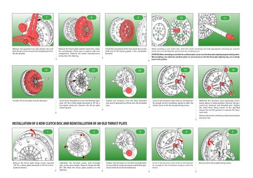
Remove the grooved nuts and remove the <strong>tool</strong><br />
from the pins, then remove the threa<strong>de</strong>d pins from<br />
the thrust plate.<br />
Position the thrust plate onto the flywheel.<br />
7 8 9<br />
10<br />
11<br />
12<br />
Remove the thrust plate and the clutch disc. Clean<br />
the components, check wear or replace with new<br />
components. Observe the clutch manufacturer's<br />
instructions for cleaning.<br />
Screw three threa<strong>de</strong>d pins into the flywheel (spacing<br />
120° for a three-spoke tensioner or 90° for a<br />
four-spoke tensioner). Observe the thrust plate<br />
centering pins.<br />
Check free movement of the new clutch disc on the<br />
shaft and of the bearing gui<strong>de</strong> in the crankshaft/<br />
flywheel.<br />
Position the tensioner onto the three threa<strong>de</strong>d<br />
pins and fit grooved nuts flush onto the threa<strong>de</strong>d<br />
pins.<br />
INSTALLATION OF A NEW CLUTCH DISC AND REINSTALLATION OF AN OLD THRUST PLATE<br />
Remove the thrust plate fixing screws (spacing<br />
120° for a three-spoke tensioner or 90° for a fourspoke<br />
tensioner).<br />
Substitute the removed screws with threa<strong>de</strong>d<br />
pins, at the same height. Observe thread size M6,<br />
M7, M8. Mark the thrust plate position on the<br />
flywheel.<br />
Position the tensioner on the three threa<strong>de</strong>d pins<br />
(in case of three-spoke tensioner) and fit three grooved<br />
nuts flush on the threa<strong>de</strong>d pins.<br />
When installing a new clutch disc, insert the clutch centering <strong>tool</strong> with appropriate centering pin and the<br />
clutch disc into the flywheel and tension the centering <strong>tool</strong>.<br />
ATTENTION! When reinstalling an old clutch disc and thrust plate, do not re<strong>set</strong> the thrust plate adjusting ring into initial position.<br />
When installing a new clutch disc and thrust plate, it is not necessary to re<strong>set</strong> the thrust plate adjusting ring, as it is already<br />
pre<strong>set</strong> in this position.<br />
13 14 15 16<br />
Screw in the tensioner stem (with an S24 spanner)<br />
far enough for the membrane spring to enter the<br />
limiter. Screw in the thrust plate fixing screws.<br />
1 2 3 4<br />
Screw in the tensioner stem (with an S24 spanner)<br />
far enough for the membrane spring to enter the<br />
limiter.<br />
Withdraw the tensioner stem backwards (membrane<br />
spring in initial position). Remove the grooved<br />
nuts, tensioner and threa<strong>de</strong>d pins. Tighten<br />
the other three fixing screws to the specified<br />
torque Use an S24 spanner to unscrew the tensioner<br />
stem.<br />
Remove the clutch centering <strong>tool</strong> by loosening the<br />
tensioner nut.<br />
Remove other thrust plate fixing screws.<br />
5