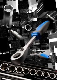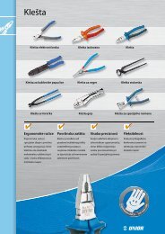
SAC Clutch tool set SAC KupplungswerkzeugSatz Outil de ... - Unior
SAC Clutch tool set SAC KupplungswerkzeugSatz Outil de ... - Unior
SAC Clutch tool set SAC KupplungswerkzeugSatz Outil de ... - Unior

Create successful ePaper yourself
Turn your PDF publications into a flip-book with our unique Google optimized e-Paper software.
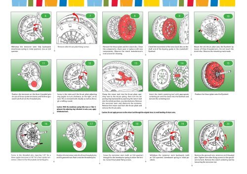
Withdraw the tensioner stem fully backwards<br />
(membrane spring in initial position). Use an S24<br />
spanner.<br />
11<br />
Position the tensioner on the three threa<strong>de</strong>d pins<br />
(in case of three-spoke tensioner) and fit three grooved<br />
nuts flush on the threa<strong>de</strong>d pins.<br />
Screw in the threa<strong>de</strong>d pins (spacing 120° for a<br />
three-spoke tensioner or 90° for a four-spoke tensioner).<br />
Observe the thrust plate centering pins.<br />
6 7 8 9 10<br />
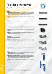
Remove other thrust plate fixing screws. Remove the thrust plate and the clutch disc. Clean Check free movement of the new clutch disc on the<br />
the components, check wear or replace with new shaft and of the bearing gui<strong>de</strong> in the crankshaft/<br />
components. Observe the clutch manufacturer's<br />
instructions for cleaning.<br />
flywheel.<br />
12<br />
Screw in the stem until the thrust plate adjusting<br />
ring begins to turn clockwise, to the right, on its<br />
own. This is noticed both visually as well as through<br />
a rattling sound.<br />
Caution: With the membrane spring fully loose or fully tightened,<br />
the adjusting ring is blocked. In such a case, apply<br />
withdrawal <strong>tool</strong>s.<br />
Position the tensioner onto the three threa<strong>de</strong>d pins<br />
and fit grooved nuts flush onto the threa<strong>de</strong>d pins.<br />
Clamp the return <strong>tool</strong> into the thrust plate opening<br />
next to the return spring, then turn the adjusting<br />
ring backwards by opening the return <strong>tool</strong><br />
into the initial position, counterclockwise. Remove<br />
the tensioner stem and dismount the tensioner.<br />
Remove the return <strong>tool</strong> from the thrust plate and<br />
remove the thrust plate.<br />
Caution: Do not apply pressure on the return <strong>tool</strong> through the original stem, to avoid bending of return arms.<br />
Screw the tensioner stem (with an S24 spanner)<br />
enough for the membrane spring to enter the limiter.<br />
Screw thrust plate fixing screws.<br />
Withdraw the tensioner stem backwards (with<br />
an S24 spanner) (membrane spring in initial position).<br />
Mount the old thrust plate onto the flywheel, by<br />
means of three threa<strong>de</strong>d pins. Do not insert the<br />
clutch disc. Observe the mounting mark ma<strong>de</strong>.<br />
13 14<br />
15<br />
Insert the clutch centering <strong>tool</strong> with appropriate<br />
centering pin and the clutch into the flywheel and<br />
tension the centering <strong>tool</strong>.<br />
16 17 18 19<br />
Position the thrust plate onto the flywheel.<br />
20<br />
Remove the grooved nuts, tensioner and threa<strong>de</strong>d<br />
pins. Tighten the other fixing screws to the specified<br />
moment. Remove the clutch centering <strong>tool</strong> by<br />
loosening the tensioner nut.