Body builder guidelines LT - Umbauportal
Body builder guidelines LT - Umbauportal
Body builder guidelines LT - Umbauportal

Create successful ePaper yourself
Turn your PDF publications into a flip-book with our unique Google optimized e-Paper software.
<strong>Body</strong> <strong>builder</strong> <strong>guidelines</strong> 2007<br />
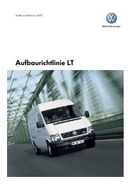
<strong>Body</strong> <strong>builder</strong> <strong>guidelines</strong> <strong>LT</strong>
The body <strong>builder</strong> <strong>guidelines</strong> define the requirements for custom body <strong>builder</strong>s and equipment fitters designing and<br />
mounting bodies or performing conversions to base vehicles of the Volkswagen Commercial Vehicles brand.<br />
The body <strong>builder</strong> <strong>guidelines</strong> must be strictly adhered to when performing any modifications to the vehicle.<br />
Ensure that no modification adversely affects the functional reliability and safety of the running gear, the body or the<br />
electric system. Modifications must only be performed by qualified specialists and in accordance with the generally<br />
acknowledged rules of the automotive industry.<br />
Prerequisites for modifications to used vehicles: The vehicle must be in a good overall condition, i.e. structural parts such<br />
as longitudinal and cross members, pillars etc. must not be corroded to such an extent that structural stability might be<br />
adversely affected.<br />
Vehicles whose modifications might affect the validity of general certificate of roadworthiness must be presented to an<br />
authorised testing centre for approval. It is recommended to clarify in advance with the relevant authority whether approval<br />
is required.<br />
When inquiring about planned modifications, please enclose two sets of design drawings of the complete scope of the<br />
modification, including weights, centre of gravity and dimensions, which also clearly show how the body is attached to the<br />
chassis. Please use the online contact form:<br />
http://www.vwn-aufbaurichtlinien.de/de/kontaktformular<br />
Please also provide information about the intended operating conditions of the vehicle. If bodies, installations or<br />
conversions comply with the present <strong>guidelines</strong>, no additional approval by Volkswagen AG is required for the presentation<br />
of the vehicle at the relevant authority examining roadworthiness.<br />
The work safety regulations of the trade association and the EU machine directive apply.<br />
When making modifications to vehicles, all corresponding and applicable legal regulations, rules, laws and directives must<br />
be observed.<br />
Note: Subject to errors and technical amendments. The electronic version of the body <strong>guidelines</strong> is the decisive source of up-to-date data on body <strong>guidelines</strong> (online body<br />
<strong>guidelines</strong>). Data status March 2009<br />
1
The body <strong>builder</strong>'s or fitter's warranty conditions apply to the body <strong>builder</strong>'s or fitter's scope of supply. Therefore, warranty<br />
claims associated with complaints to this scope of supply cannot be made under the warranty conditions applicable to<br />
Volkswagen Commercial Vehicles.<br />
Volkswagen vehicles delivered after 01. January 2005 are covered by a 2-year warranty without mileage limitation for the<br />
flawless condition of the product (Volkswagen warranty).<br />
Defects of bodies, installations and conversions provided by third parties as well as defects of the vehicle caused by the<br />
said bodies, installations or conversions are excluded from the Volkswagen warranty and also from the Volkswagen paint<br />
and body warranty. This also applies to accessories which were not installed and/or supplied by the vehicle manufacturer.<br />
The body <strong>builder</strong> or fitter is solely responsible for the design and assembly of bodies and the execution of conversions.<br />
All conversions must be documented by the body <strong>builder</strong> or fitter in the service schedule provided with every Volkswagen<br />
vehicle.<br />
Due to the multitude of conversions and diversity of operating conditions, the information provided by Volkswagen AG is<br />
subject to the reservation that modified vehicles are not tested by Volkswagen AG. Modifications may affect the properties<br />
of the vehicle.<br />
For reasons of liability, the body <strong>builder</strong>s or fitters must provide the following information in writing to their<br />
customers:<br />
"Due to the modifications* to your Volkswagen Commercial Vehicles base vehicle, the properties of your base vehicle may<br />
have changed.<br />
Please understand that Volkswagen AG does not assume any liability for any negative effects resulting from the<br />
modifications* to the vehicle."<br />
* At this point, the term "modification" may be substituted by a more precise description of the work performed, e.g. by<br />
"camping equipment installation", "wheelbase extension", "box body".<br />
In individual cases, Volkswagen AG reserves the right to demand proof of the information being passed on to the<br />
customer.<br />
No general legal entitlement for the approval of a body modification exists, even if such approval was previously granted.<br />
Bodies, installations or conversions complying with the present <strong>guidelines</strong> do not require additional approval by<br />
Volkswagen AG to be presented at the authorised examining body.<br />
Note: Subject to errors and technical amendments. The electronic version of the body <strong>guidelines</strong> is the decisive source of up-to-date data on body <strong>guidelines</strong> (online body<br />
<strong>guidelines</strong>). Data status March 2009<br />
2
Extended storage times cannot always be avoided. The following measures are recommended to ensure that vehicle<br />
quality is not affected by long-term storage:<br />
At vehicle delivery:<br />
• Fill tank<br />
• Do not park the vehicle under trees, poles; etc.<br />
• Open all ventilation flaps, set blower to maximum speed<br />
• Disconnect battery(ies)<br />
• Remove dirt, snow and moisture from vehicle (footwell)<br />
• Close windows, doors, front lid, rear lid and sunroof<br />
• Put manual gearbox into 1st gear or lever of automatic gearbox into park position. Do not engange reverse gear.<br />
Do not apply the parking brake.<br />
• Remove the windscreen wiper bags and prop up the wiper arm using a foam pad, remove any loose protective<br />
film. ("Aero wipers": remove and store in suitable location inside vehicle).<br />
• Check tyre pressures; increase to 4.5 bar for commercial vehicles, if required.<br />
Check vehicles weekly for contamination by aggressive media (e.g. bird droppings, industrial dusts) and clean, if required.<br />
Check battery open-circuit voltage every three months. Open-circuit voltage means the voltage of the disconnected<br />
battery after a minimum storage period of 12 hours. Recharge battery in due time before it reaches an open-circuit voltage<br />
of 12.4 volt ('magic eye' changes from green to black). Batteries with an open-circuit voltage of less than 11.6 volt are in<br />
state of exhaustive discharge and should be disposed of soon.<br />
Batteries must be recharged only with current-controlled and voltage-limited chargers. A maximum charging voltage of<br />
14.4 volt must not be exceeded.<br />
It is recommended to check the tyre inflation pressure every three months and to increase it to 4.5 bars for commercial<br />
vehicles, if required.<br />
Reconnect battery negative lead(s) before recommissioning the vehicle.<br />
Note: Subject to errors and technical amendments. The electronic version of the body <strong>guidelines</strong> is the decisive source of up-to-date data on body <strong>guidelines</strong> (online body<br />
<strong>guidelines</strong>). Data status March 2009<br />
3
Fitters of accessories and body <strong>builder</strong>s must ensure that they comply with all applicable environmental rules and<br />
regulations, especially EU directive 2000/53/EC concerning end-of-life vehicles and EU directive 2003/11/EC relating to<br />
restrictions on the marketing and use of certain dangerous substances and preparations.<br />
The vehicle owner must keep all assembly documentation concerning the modification and hand them over together with<br />
the vehicle to the dismantler. This ensures that modified vehicles are processed in compliance with environmental rules<br />
and regulations at the end of their lifecycle.<br />
Note: Subject to errors and technical amendments. The electronic version of the body <strong>guidelines</strong> is the decisive source of up-to-date data on body <strong>guidelines</strong> (online body<br />
<strong>guidelines</strong>). Data status March 2009<br />
4
Maintenance instructions or service schedules outlining inspection and servicing work should be provided for the<br />
modifications performed by the body <strong>builder</strong> or accessories fitter. These instructions or schedules must include the<br />
maintenance and inspection intervals as well as the required operating fluids and materials and the spare parts. Parts and<br />
components with a limited service life which must be checked in regular intervals to ensure service reliability and timely<br />
replacement must be explicitly stated.<br />
This should be supported by a repair manual including tightening torques, settings and tolerances as well as other<br />
relevant specifications. Special tools, including their source of supply, must also be stated.<br />
The manual must also state which type of work must be performed only by the body <strong>builder</strong>s and accessories fitters or<br />
their authorised workshops.<br />
If the body <strong>builder</strong>s or accessory fitter's scope of supply includes electric, electronic or mechatronic, hydraulic or<br />
pneumatic systems, circuit diagrams and diagnosis routines or similar documentation facilitating a systematic search for<br />
faults must be provided.<br />
Note: Subject to errors and technical amendments. The electronic version of the body <strong>guidelines</strong> is the decisive source of up-to-date data on body <strong>guidelines</strong> (online body<br />
<strong>guidelines</strong>). Data status March 2009<br />
5
<strong>Body</strong> <strong>builder</strong>s must ensure that the fitted components, conversions, bodies and modifications comply with applicable legal<br />
rules and regulations as well as all regulations regarding work safety and accident prevention. All safety rules and the<br />
information material provided by accident insurance providers must be observed.<br />
All technically feasible measures must be taken to prevent unsafe operation.<br />
Country-specific laws, directives and approval regulations must be observed.<br />
The body <strong>builder</strong> or device or equipment manufacturer is responsible for the compliance with these laws, rules and<br />
regulations.<br />
For further information about commercial freight traffic in the Federal Republic of Germany please contact:<br />
Berufsgenossenschaft für Fahrzeughaltung<br />
Fachausschuss "Verkehr"<br />
Sachgebiet "Fahrzeuge"<br />
Ottenser Hauptstraße 54<br />
22765 Hamburg, Germany<br />
Homepage: www.bg-verkehr.de<br />
E-Mail: info@bg-verkehr.de<br />
Note: Subject to errors and technical amendments. The electronic version of the body <strong>guidelines</strong> is the decisive source of up-to-date data on body <strong>guidelines</strong> (online body<br />
<strong>guidelines</strong>). Data status September 2010<br />
6
Extras: The standard vehicle can be prepared ex-works for the desired attachment. Please, check the attachment-relevant<br />
extras before ordering the vehicle. Ordering options and prices are included in the sales documents.<br />
7
• Exhaust gas pipe, lateral<br />
• End cross-member (omitted at chassis)<br />
• Increase of axle load, front (<strong>LT</strong> 35)<br />
8
• Reductions of total weight<br />
• Absorption of external noise<br />
• Exterior mirror (bracket)<br />
• Battery power / 2nd battery<br />
• Flashing indicators, lateral (for wide attachments)<br />
• Damping for high attachments<br />
• Differential lock<br />
• Rpm governor<br />
• Tachograph<br />
• Generator power / 2nd generator<br />
• Rear axle gear ratio<br />
• Coolant compressor<br />
• Auxiliary drive of standard transmission<br />
• Spare-wheel support<br />
• SBBR line (700 mm reserve)<br />
• SBBR lamp preparation<br />
• Stabilizers<br />
• Connection socket 12 V in the seat box<br />
• Telephone/D-Netz [mobile phone network] preparation<br />
• Underrun protection<br />
• Wheel chocks<br />
• Periphery lamps<br />
• Fastening lugs box-type delivery van/station wagon<br />
• VW emblem, rear doors (steering)<br />
• Warning lamp, triangle and first-aid kit<br />
• Heat isolation<br />
• Cowl<br />
• Auxiliary heating<br />
• Auxiliary instruments (switches for electronic installations)<br />
Note: Subject to errors and technical amendments. The electronic version of the body <strong>guidelines</strong> is the decisive source of up-to-date data on body <strong>guidelines</strong> (online body<br />
<strong>guidelines</strong>). Data status March 2009<br />
9
• standard design<br />
• favourable traction with full payload<br />
• service-friendly<br />
• low air resistance<br />
• good entrance and passing-through possibility<br />
• high load-carrying capacity of the chassis<br />
• highly chargeable torsion-resistant cap-profile frame<br />
• even upper belt<br />
• attachment fixing already installed<br />
• appropriate wheel bases<br />
• selectable rear axle gear ratio for individual operating conditions<br />
• efficient engine offer - environmentally friendly and consumption-oriented<br />
• high trailing load<br />
• easy to write on, large-surface side walls at box-type delivery van<br />
• full standing height in high-space box-type delivery vans (high roof made of steel)<br />
• Volkswagen quality<br />
Note: Subject to errors and technical amendments. The electronic version of the body <strong>guidelines</strong> is the decisive source of up-to-date data on body <strong>guidelines</strong> (online body<br />
<strong>guidelines</strong>). Data status March 2009<br />
10
The weights and axle loads (permissible/empty) for the <strong>LT</strong> attachment variants - box-type delivery van, chassis with<br />
cab/double cab, can be downloaded in the download area, together with the appropriate drawings. For the chassis with<br />
cowl (without roof and back wall), the weight has to be reduced by approx. 50 kg compared to the chassis with cab.<br />
Note:<br />
To ensure a sufficient manoeuvrability of the vehicle, the minimum front axle load must amount to 25% of the total weight.<br />
In the case of vehicles with loading tailboard, the minimum front axle load must amount to 30% of the total weight.<br />
The indicated unloaded-state weights refer to the standard vehicle equipment (including driver, spare wheel, tool and filled<br />
fuel tank). Weight tolerances of +5% are permitted according to STVZO [German traffic regulations] and are to be taken<br />
into consideration, where appropriate.<br />
If extras are installed, the permitted unloaded weight increases. If required, the final unloaded vehicle weight is to be<br />
determined using a scale.<br />
Note: Subject to errors and technical amendments. The electronic version of the body <strong>guidelines</strong> is the decisive source of up-to-date data on body <strong>guidelines</strong> (online body<br />
<strong>guidelines</strong>). Data status August 2007<br />
11
The weights must never exceed the<br />
• permissible total weight<br />
• permissible front axle load<br />
• permissible rear axle load.<br />
When projecting attachments, it has to be ensured that a single-sided weight distribution is avoided - in particular if fixed<br />
attachments are to be installed. If it is not possible to adhere to this recommendation, the single-sided load may only result<br />
in a maximum difference between the wheel loads of 8%.<br />
Note:<br />
Observe the tyre load-carrying capacity!<br />
Example:<br />
Permitted axle load 2.000 kg<br />
theoretical wheel load left/right 1.000/1.000 kg<br />
4% of this wheel load 40 kg<br />
Permitted wheel load distribution left/right 1.040 kg/960 kg<br />
Note: Subject to errors and technical amendments. The electronic version of the body <strong>guidelines</strong> is the decisive source of up-to-date data on body <strong>guidelines</strong> (online body<br />
<strong>guidelines</strong>). Data status August 2007<br />
12
The chassis dimensions are shown in the drawings. The drawings are available in the "Download" section. They can be<br />
downloaded and used for planning/constructing.<br />
When you are using tyre sizes which are differing from the standard equipment, the vehicle and chassis heights<br />
(measured from ground level) may change. In this case, it is necessary to consider these deviations during projecting.<br />
Important note:<br />
• The minimum distance between cab and attachment must be at least 50 mm.<br />
• The rear overhang of the attachments may under no circumstances exceed the default values indicated in the<br />
following table.<br />
• The distance between the rear edge of the attachment and the rear edge of the end cross-member/underrun<br />
protection must not exceed 400 mm.<br />
[Translate to English:] Aufbauaußenlängen und Fahrzeugüberhänge für Fahrgestelle mit Fahrerhaus/Doppelkabine<br />
(Doka):<br />
Modell Karosserie Radstand<br />
(mm)<br />
<strong>LT</strong> 28 Fahrerhaus/-<br />
Fahrerhaus/Doka<br />
<strong>LT</strong> 35 Fahrerhaus/-<br />
Fahrerhaus/Doka<br />
Fahrerhaus/Doka<br />
3.000<br />
3.550<br />
3.000<br />
3.550<br />
4.025<br />
max.<br />
Fahrzeugüberhang<br />
mit<br />
Überhangverlängerung/<br />
spezif.<br />
Unterfahrschutz<br />
(mm)<br />
1.500/-<br />
1.775/-<br />
1.500/-<br />
1.775/-<br />
2.060<br />
Empfohlener<br />
Fahrzeugüberhang<br />
ohne<br />
Überhangverlängerung<br />
(mm)<br />
1.340/-<br />
1.340/1.410<br />
1.340/-<br />
1.340/1.410<br />
1.620/1.490<br />
Empfohlene<br />
Aufbauaußenlänge<br />
ohne<br />
Überhangverlängerung<br />
(mm)<br />
2.980/-<br />
3.530/2.800<br />
2.980/-<br />
3.530/2.800<br />
4.290/3.350<br />
13
<strong>LT</strong> 46 Fahrerhaus/-<br />
Fahrerhaus/Doka<br />
3.550<br />
4.025<br />
1.775/-<br />
2.060<br />
1.690/1.480<br />
1.940/1.840<br />
3.880/2.870<br />
4.600/3.700<br />
Bei Fahrgestellen mit Doka sind größere Fahrzeugüberhänge (als empfohlen) nur nach Rücksprache mit der<br />
Volkswagen AG zulässig. Auch bei den empfohlenen Aufbaulängen ist durch eine Lastverteilungsrechnung die<br />
Einhaltung der Mindest-Vorderachslast und der zulässigen Achslasten zu überprüfen.<br />
Note: Subject to errors and technical amendments. The electronic version of the body <strong>guidelines</strong> is the decisive source of up-to-date data on body <strong>guidelines</strong> (online body<br />
<strong>guidelines</strong>). Data status August 2007<br />
14
Numerous <strong>guidelines</strong> are to be adhered to, when chassis is to be transported on their own axles:<br />
• Wheel cover<br />
• Ballast weight for braking<br />
• Lateral starting protection<br />
• Lighting equipment<br />
These parts are neither developed nor on-stock, thus making the transport on own axle unnecessarily expensive. For this<br />
reason, the self-pickup of chassis is no longer possible. It is recommended to deliver the chassis by rail or truck.<br />
Note: Subject to errors and technical amendments. The electronic version of the body <strong>guidelines</strong> is the decisive source of up-to-date data on body <strong>guidelines</strong> (online body<br />
<strong>guidelines</strong>). Data status August 2007<br />
15
For attaching a loading tailboard, it is required to consider the following instructions:<br />
• The permitted rear-axle load must not be exceeded.<br />
• Consider minimum front-axle load (i. e. 30% of the total vehicle weight).<br />
• Check the stability.<br />
• Calculate the load distribution including all extras.<br />
• If required, shorten attachment length and rear overhang.<br />
• Guide subframe as far as possible to the front and realise a force-locked connection with the chassis frame.<br />
• Standard box-type delivery vans require no subframe.<br />
• A stabilizer bar is necessary for the front and rear axle.<br />
• If possible, use only hydraulic supporting devices. Do not lift the vehicle with the supporting device (chassis may<br />
be damaged)<br />
• Load distance max. 500 mm<br />
• Security<br />
The regulations for the prevention of industrial accidents and the EC Machinery Directive are to be adhered to.<br />
Check for underrun protection and lighting devices.<br />
• The standard vehicle can be provided ex-works with the required extras item 1.3).<br />
Vehicles with double cab may only be provided with a loading tailboard in special cases. The mounting is only permitted<br />
with the permission of Volkswagen AG.<br />
Maximum load-carrying capacity and profile<br />
dimensions:<br />
Models WheelbaseLifting<br />
Minimum<br />
(mm) power dimensions<br />
to n KN Subframe<br />
side rail*<br />
<strong>LT</strong> 28-chassis 3.000<br />
3.550<br />
<strong>LT</strong> 35-chassis 3.000<br />
3.550<br />
4.025<br />
<strong>LT</strong> 46-chassis 3.550<br />
4.025<br />
<strong>LT</strong> 28-box-type 3.000<br />
delivery van 3.550<br />
<strong>LT</strong> 35-box-type 3.000<br />
delivery van 4.550<br />
3.025<br />
<strong>LT</strong> 46-box-type 3.550<br />
delivery van 4.025<br />
5<br />
5<br />
5<br />
5<br />
5<br />
7,5<br />
7,5<br />
3<br />
3<br />
3<br />
3<br />
3<br />
3<br />
3<br />
80 x 45 x 3<br />
80 x 45 x 3<br />
80 x 45 x 3<br />
80 x 45 x 3<br />
120 x 50 x 4<br />
120 x 50 x 4<br />
140 x 60 x 5<br />
-<br />
-<br />
-<br />
-<br />
-<br />
-<br />
-<br />
The specified minimum dimensions refer to normal operating conditions and applications without overhang extension.<br />
16
For example, when working with a lifting hoist, the entire vehicle may be lifted on 4 hydraulic pillars -the wheels lose all<br />
contact with the ground. Due to the heavy weight of the front of the vehicle, this causes impermissibly high tension in the<br />
longitudinal frame members in the area of the front support.<br />
A reinforcement of the chassis frame is essential for such applications. To this end, fit a mounting frame through the rear<br />
wall of the cab under the base of the seats and secure this with an additional console and a bolt connection. A suggestion<br />
as to how this can be implemented can be given on request by the responsible department.<br />
An additonal battery as per PR-No. 8FV (location underbase of co-driver's seat) is not possible with this configuration and<br />
also for the <strong>LT</strong> 46.<br />
Note: Subject to errors and technical amendments. The electronic version of the body <strong>guidelines</strong> is the decisive source of up-to-date data on body <strong>guidelines</strong> (online body<br />
<strong>guidelines</strong>). Data status August 2007<br />
17
When laying out the loading crane attachments, it is required to observe - apart from the necessary stability - the<br />
connection between loading crane and chassis (item 3.4).<br />
Loading crane and vehicle attachment are to be arranged in such a way, that the permitted axle loads are kept in every<br />
loading state.<br />
Loading crane attachment behind the drivers cab<br />
• Maximum crane-load moment: 25 KNm<br />
Moments of resistance for mounting-frame side rails: Wx = 45cm3 •<br />
(45cm3 (profile dimensions according to<br />
diagram under item 3.3)<br />
• Determine the flatbed length depending on the loading-crane attachment.<br />
• Due to the load distribution, it may be necessary to lengthen the chassis.<br />
• A permission is required for deviating crane attachments.<br />
• The necessary supporting devices should be hydraulically actuated.<br />
• Do not lift the vehicle with the supporting device (chassis may be damaged)<br />
• Crane attachments and supporting devices must neither impair other equipment, modules, units, etc., nor the<br />
associated functions.<br />
• Loading crane attachments must meet the requirements of the regulations for the prevention of industrial<br />
accidents and the EC Machinery Directive.<br />
Note: Subject to errors and technical amendments. The electronic version of the body <strong>guidelines</strong> is the decisive source of up-to-date data on body <strong>guidelines</strong> (online body<br />
<strong>guidelines</strong>). Data status December 2007<br />
18
According to article §51b. of the German motor vehicle traffic regulations (STVZO), vehicles with a width of more than<br />
2,100 mm must be provided with parking lamps when they are to be used in the Federal Republic of Germany.<br />
As standard, all chassis and chassis with flatbed attachment are not provided with parking lamps (standard vehicle width<br />
1,922 mm and 1,990 mm).<br />
In the <strong>LT</strong> delivery program, the tipper with single and double cab as well as the <strong>LT</strong>46 Pick up with single and double cab<br />
exceeds the pre-set vehicle width (standard width: 2,120 mm). At these vehicles, parking lamps are assembled in front on<br />
the side on the cab roof. In addition, the outside chambers of the 6-chamber lamps at the vehicle rear are designed as<br />
parking lamps (series equipment: PR-No. 6S1).<br />
When ordering a chassis that is to be used for an attachment with a width of more than 2,100 mm, it is required to order<br />
also back and front parking lamps (PR-No. 6S1).<br />
If the intended vehicle width exceeds 2,100 mm and if the rear parking lamps are to be mounted by the attachment<br />
manufacturer, it is only possible to order parking lamps that are to be mounted on the roof in front (PR-No. 6S3) (SBBR<br />
lamps can be left out at PR-No. 8SZ; preparation SBBR lamp).<br />
Note: Subject to errors and technical amendments. The electronic version of the body <strong>guidelines</strong> is the decisive source of up-to-date data on body <strong>guidelines</strong> (online body<br />
<strong>guidelines</strong>). Data status August 2007<br />
19
According to article §51a. of the German motor vehicle traffic regulations (STVZO), vehicles with a length of more than 6<br />
m must be provided with yellow side marker lamps and lateral reflectors.<br />
In the <strong>LT</strong> delivery program, only the chassis with long wheel base exceeds the pre-set vehicle length.<br />
If required, all standard vehicles are to be provided with reflecting side marker lamps.<br />
All chassis with long wheel base are prepared ex-works for side marker lamps (wiring harness). The attachment<br />
manufacturer is responsible for installing side marker lamps.<br />
Note: Subject to errors and technical amendments. The electronic version of the body <strong>guidelines</strong> is the decisive source of up-to-date data on body <strong>guidelines</strong> (online body<br />
<strong>guidelines</strong>). Data status August 2007<br />
20
According to article §54 of the German motor vehicle traffic regulations (STVZO), multitrack vehicles must be provided at<br />
the long sides with additional flashing indicators to be mounted in the first third of the front section.<br />
If the permitted total weight is more than 3.5 t, the light intensity of these flashing indicators must lie between 50 cd (min.)<br />
and 200 cd (max.). All vehicles with a permitted total weight of less than 3.5 t are to be provided with small lateral flashing<br />
indicators (5W). All vehicles with a total weight of more than 3.5 t are to be provided with large lateral<br />
flashing indicators (21W).<br />
Minimum visual angle ranges are pre-defined for mounting of lateral flashing indicators. As a result, it is mandatory to<br />
mount various flashing indicators, depending on the attachment width: Small lateral flashing indicators<br />
• Width up to 2,100 mm<br />
Large lateral flashing indicators<br />
• Width between 2,101 and 2,200 mm<br />
Large lateral flashing indicators with adapter<br />
• Width between 2,201 and 2,500 mm<br />
Due to the confinements imposed by vehicle length (cf., item 3.13), permitted total weight and attachment width, the<br />
required combinations of flashing indicators/marker lamps are already pre-defined for standard vehicles. Only attachment<br />
widths of more than 2,200 mm require large lateral flashing indicators with adapter (can be ordered, PR-No. 8F8).<br />
Note: Subject to errors and technical amendments. The electronic version of the body <strong>guidelines</strong> is the decisive source of up-to-date data on body <strong>guidelines</strong> (online body<br />
<strong>guidelines</strong>). Data status August 2007<br />
21
According to EU Directive 76/756 EEC and article §54 of the German motor vehicle traffic<br />
regulations (STVZO), motor cars that are to be used in the Federal Republic of Germany must<br />
be provided with mirrors. These mirrors must be designed and installed in such a way to permit<br />
the driver to look backwards and sideways - also if a trailer is hooked up to the vehicle - so that<br />
he or she is capable of observing the traffic.<br />
As standard, all <strong>LT</strong>-model are equipped with an interior mirror and a exterior mirror - for a max.<br />
attachment width of up to 2,150 mm.<br />
For attachment widths between 2,150 mm and 2,400 mm, exterior bracket mirrors are available<br />
(normal/large bow).<br />
Availability of <strong>LT</strong> exterior mirrors<br />
(see also Sales Manual):<br />
• Standard mirror (serial) - attachment widths up to 2,150 mm<br />
• Bracket exterior mirror, normal (standard dump truck and <strong>LT</strong> 46 chassis) - attachment<br />
widths between 2,151 mm and 2,300 mm<br />
• Bracket exterior mirror, large - attachment widths between 2,301 mm and 2.400 mm<br />
Note: Subject to errors and technical amendments. The electronic version of the body <strong>guidelines</strong> is the decisive source of up-to-date data on body <strong>guidelines</strong> (online body<br />
<strong>guidelines</strong>). Data status August 2007<br />
22
The attachment manufacturer has to ensure that<br />
• it is possible to mount the largest permissible tyre size,<br />
• the distance between tyres and mudguard or wheel housing is sufficient, even with mounted snow chains or<br />
antiskid protection chains and with full single-sided or two-sided compression. Consider the dimensions that are<br />
specified in the chassis drawings.<br />
<strong>LT</strong> wheels/tyres/allocation<br />
Disk wheel Tyre<br />
<strong>LT</strong> 28 5 1 / 2 J x 15 H2<br />
(press-in depth<br />
195/70 R15 C 104/102 R<br />
(Special equipment)<br />
83 mm)<br />
6 J x 15 H2 225/70 R15 C 112/110 R<br />
<strong>LT</strong> 35 6 J x 15 H2 225/70 R15 C 112/110 R<br />
Twin tyres at the back<br />
<strong>LT</strong> 46 5 1 / 2 J x 15 H2<br />
(press-in depth<br />
115 mm)<br />
195/70 R15 C 104/102 R<br />
Note: Subject to errors and technical amendments. The electronic version of the body <strong>guidelines</strong> is the decisive source of up-to-date data on body <strong>guidelines</strong> (online body<br />
<strong>guidelines</strong>). Data status August 2007<br />
23
The standard spare-wheel positions, depending on car-body design and motorization and according to the following<br />
overview/assignment matrix, are shown in the box-type delivery van and chassis drawings.<br />
Assignment - <strong>LT</strong> spare wheel/spare wheel support<br />
Car-body design Model Engine PR-Nr.<br />
1BO 1B1 1B2 1B5 1B9<br />
Box-type delivery van <strong>LT</strong> 28/35/46 Diesel o x - o -<br />
Chassis with cab <strong>LT</strong> 28/35 Diesel o o x - o<br />
<strong>LT</strong> 46 Diesel o x - - -<br />
Chassis with double cab <strong>LT</strong> 28/35 Diesel o o x - o<br />
<strong>LT</strong> 46 Diesel o x - - -<br />
x = Standard production type<br />
o = Special equipment<br />
PR-No. 1B0 = Without spare wheel support (enforces "Without spare wheel (PR-No. 1G0)")<br />
PR-No. 1B1 = Normal spare wheel support - behind the rear axle, below the frame<br />
PR-No. 1B2 = Spare wheel support for double cab and drivers cab - on the right side rail<br />
PR-No. 1B5 = Spare wheel support in the interior - behind the wheel housing<br />
PR-No. 1B9 = Spare wheel support for double cab and driver's cab - provisionally attached on the right side rail. The<br />
attachment manufacturer is responsible for the final attachment according to official regulations (easy access, simple<br />
operation, dual protection against losing) ("1B9" enforces: "Without flatbed bottom frame (PR-No. 5HA/5HJ)")<br />
In case of deviations from the ex-works spare-wheel attachments (this does not apply to fastenings at the<br />
attachment), it is required to ask the responsible department for a permission<br />
Note: Subject to errors and technical amendments. The electronic version of the body <strong>guidelines</strong> is the decisive source of up-to-date data on body <strong>guidelines</strong> (online body<br />
<strong>guidelines</strong>). Data status August 2007<br />
24
According to EU Directive 70/221 EEC and article §32 b. of the German motor vehicle traffic<br />
regulations (STVZO), motor cars at which the distance between rear limitation and rear axle is<br />
more than 1,000 mm and which have, in unloaded condition, a headroom of more than 700<br />
mm (applying either to the total width of the rear chassis or the main car-body parts) above<br />
lane, must be provided with an underrun protection.<br />
At all <strong>LT</strong> vehicles, the main car-body parts lie less than 700 mm above lane. For this reason,<br />
standard vehicles require no underrun protection. As standard, all <strong>LT</strong> 46 chassis models<br />
(with/without flatbed) are equipped with a rear underrun protection.<br />
The maximum distance between the rear edge of the attachment and the main car-body parts<br />
(at the chassis, this applies to the bulb retainers) is 400 mm. If 400 mm are exceeded, the<br />
attachment manufacturer is obliged to construct and install an underrun protection<br />
corresponding to the relevant EU Directives.<br />
For this purpose, it is recommended to use the screw connections at the frame that are<br />
provided for the trailer coupling.<br />
Note: Subject to errors and technical amendments. The electronic version of the body <strong>guidelines</strong> is the decisive source of up-to-date data on body <strong>guidelines</strong> (online body<br />
<strong>guidelines</strong>). Data status August 2007<br />
25
According to EU Directive 89/297 EEC and article §32 c. of the German motor vehicle traffic<br />
regulations (STVZO), motor cars whose permitted total weight exceeds 3.5 t and whose main<br />
car-body parts have a headroom of more than 500 mm above lane, must be provided with<br />
lateral protectors, if these vehicles are to be used in the Federal Republic of Germany.<br />
Excluded from this regulation are tractive units, driven machines and special vehicles whose<br />
operational purpose cannot be fulfilled by the lateral protectors.<br />
As standard, all <strong>LT</strong> 46 flatbed models are provided with lateral protectors. At the <strong>LT</strong> chassis<br />
(cab/double cab without flatbed), no lateral protectors are mounted. The lateral protectors must<br />
be constructed and installed by the attachment manufacturer relating to the attachments<br />
according to the relevant EU directive.<br />
If lateral protectors are to be installed subsequently, the following instructions apply:<br />
• Component parts, such as battery box, air receivers, petrol tanks, lamps, reflectors,<br />
spare wheels and tool boxes, may be installed if the prescribed distance dimensions<br />
are kept. Brake, air or hydraulic lines and other parts must not be attached to the<br />
lateral protector.<br />
• Function and accessibility of all equipment, modules, units, etc. of the vehicle must<br />
not be impaired.<br />
Note: Subject to errors and technical amendments. The electronic version of the body <strong>guidelines</strong> is the decisive source of up-to-date data on body <strong>guidelines</strong> (online body<br />
<strong>guidelines</strong>). Data status August 2007<br />
26
There are clear instructions available for handling vehicles with longer service lives (see manual Service Technology,<br />
volume: Inspection and Maintenance, item 3.2.4, Storage of Brand-New Vehicles). These instructions are defined by the<br />
customer service and are to be adhered to. Observe the following note when handling the tachograph: If the acceptance<br />
stamp is older than six months, the tachograph should be re-submitted to an acceptance test.<br />
Note: Subject to errors and technical amendments. The electronic version of the body <strong>guidelines</strong> is the decisive source of up-to-date data on body <strong>guidelines</strong> (online body<br />
<strong>guidelines</strong>). Data status August 2007<br />
27
General information<br />
• The attachment of the trailer coupling must correspond to the specific directives of the relevant country. In the<br />
Federal Republic of Germany, standard DIN 74 050 has to be complied with.<br />
• Consider free-space dimensions*. In the Federal Republic of Germany, standard DIN 74.058 has to be complied<br />
with.<br />
• If deviations from the German regulations for the prevention of industrial accidents (UVV) are necessary, it is<br />
required in the Federal Republic of Germany to request an import certificate ["Unbedenklichkeitsbescheinigung"]<br />
from: Berufsgenossenschaft für Fahrzeughaltung [German Trade Co-operative Association for Matters<br />
Associated with Car Owning], 22757 Hamburg (phone +49 [0] 40/38 10 91).<br />
• If trailer couplings are to be installed subsequently, only products which have been approved by us and original<br />
Volkswagen end cross-members may be used. Attachment points are available at our end cross-member and/or<br />
side rail.<br />
• The size of the trailer coupling is defined according to the D-value.<br />
The size of the trailer coupling is defined according to the D-value<br />
D = control-shaft value<br />
mk = permitted total weight of the tractor (motor car) in t<br />
mA = permitted total weight of the trailer in t<br />
g = 9,80665 m/s 2<br />
The permitted trailing load can be taken from the valid sales documents or the guide "Trailer<br />
Operation". In order to permit the trailers being exchanged in transborder traffic, the distance<br />
dimension, x, must not exceed 300 mm.<br />
* If the trailer is extremely low lying or if a special attachment is extremely overhanging, it may<br />
be prohibited to use a trailer coupling.<br />
Mouth clutch (can be ordered ex works under PR-No.1D5)<br />
• Max. distance between the middle of clutch bolt of the trailer coupling and attachment<br />
end: 420 mm. Keep clearances.<br />
• In special cases, it is permitted to exceed the distance dimension of 420 mm: Max.<br />
distance 650 mm for vehicles with tiltable attachments or rear attachments. Max.<br />
distance 1,320 mm, if the headroom between lane and the lower attachment edge is<br />
at 1,150 mm. A suitable remote control for the clutch must be available. The safe<br />
actuation of the clutch must not be impaired.<br />
28
Spherical coupler (can be ordered ex works under PR-No.1D1)<br />
• Keep clearances.<br />
• The installation is only permitted at approved trailing supports.<br />
• It is not permitted to perform the installation only at the underrun protection. Modifications of the underrun<br />
protection must be arranged with the responsible testing and research laboratory (in Germany: TÜV).<br />
Note: Subject to errors and technical amendments. The electronic version of the body <strong>guidelines</strong> is the decisive source of up-to-date data on body <strong>guidelines</strong> (online body<br />
<strong>guidelines</strong>). Data status August 2007<br />
29
An operating permit is available for the brake system of the vehicles. This licensing becomes invalid if the brake system is<br />
modified. Therefore, modifications of the brake system are illegal.<br />
If it cannot be avoided to perform works on the brake system, e. g. changing the wheel base, the following instructions are<br />
to be considered:<br />
• Replace hydraulic brake lines completely.<br />
• Dimensions of roller laminated tube: 4.75 x 0.7; plastic lines/tubes are not permitted.<br />
• Mould lines only with a bending fixture<br />
• Bend radius = 17.5 mm<br />
• Clean the interior of lines.<br />
• Keep safety clearance to heat sources, pointed, sharp or moving parts<br />
• Attachment with plastic loops, max. distance 500 mm<br />
• Let the ALB controller be re-adjusted by a VW dealer if the weight has changed.<br />
After finishing works, check whether the brake system is perfectly functioning.<br />
Retarder<br />
• If a retarder is to be subsequently installed at the transmission or in the drive-shaft strand, it is required to ask the<br />
responsible department for a permission. Approvals are not generally given but are basically limited to specific<br />
vehicle designs and wheel bases.<br />
The mounting drawings must include the following information:<br />
• Position of the retarder in the vehicle<br />
• Drive-shaft angle<br />
• Length of the drive shafts<br />
• Due to the additional weight of the retarder, the distribution of weight and adherence of the permitted axle loads<br />
has to be checked. Check location of the centre of mass of the attachment. Adjust it, if required.<br />
• Mounting is only permitted at vehicles with sufficiently dimensioned electrical installation (generators and<br />
batteries with sufficient capacity). Ensure a sufficient ground connection of the retarder.<br />
• Ensure sufficient freedom of operation.<br />
• In the drive-shaft strand, attach the retarder only at the bar of the chassis frame using brackets with silent blocks.<br />
• Protect lines against heat by using an appropriate insulation. The permitted maximum temperature for polyamide<br />
lines is 80°C.<br />
Note: Subject to errors and technical amendments. The electronic version of the body <strong>guidelines</strong> is the decisive source of up-to-date data on body <strong>guidelines</strong> (online body<br />
<strong>guidelines</strong>). Data status August 2007<br />
30
Power output of the engine via v-belts<br />
At the engine, the output can be decreased by max. 10 kW via v-belts, if the available flange points are being used.<br />
Versions available ex works:<br />
optional:<br />
• Power steering pump/steering booster pump, standard<br />
• 2. Generator, 90 A (PR-No. 8HB)<br />
• Refrigerant compressor (PR-No. 2AB), operative compressor installed in the vehicle, Sanden SD7 H 15<br />
(non-controlled)<br />
• Hydraulic pump as enclosed package (PR-No. 2BD) preparation for installation<br />
At backfitting of a refrigerant compressor it is important to order the preparation refrigerant compressor (PR-No. 2AC).<br />
Otherwise you have to assemble the original parts. Differing parts can cause damages (for example, fracture of the<br />
clamping element).<br />
Auxiliary drive of standard transmission<br />
Actuation is realised via the countershaft of the transmission<br />
Versions available ex works:<br />
Module PR-Number<br />
ZSBTransmission without auxiliary drive, standard 0R0<br />
ZSBTransmission with auxiliary drive<br />
Countershaft without flange<br />
ZSBTransmission with auxiliary drive<br />
Countershaft with flange<br />
ZSBTransmission with auxiliary drive<br />
Switch lock for transmission<br />
Countershaft without flange<br />
ZSBTransmission with auxiliary drive<br />
Switch lock for transmission<br />
Countershaft with flange<br />
Power take-offs are not available for 2,5l diesel TDI(61kW).<br />
0R1<br />
0R3<br />
0R6<br />
0R7<br />
The electronical engine speed govemor (PR-No. 6Y3, 6Y6) is only available for power take-offs (PR-No. 0R6, 0R7).<br />
Notes:<br />
31
• The design of the auxiliary drive and the selection of the gear ratio depend on the power and speed (revolutions<br />
per minute) of the modules to be actuated.<br />
• Transmission-dependent auxiliary drives may only be switched on/off with the vehicle standing still.<br />
• Information on max. transmissible torques (Nm) of the individual auxiliary drives can be taken as guide values for<br />
shock-free and non-oscillating operation. According to DIN 922, the above specifications are based on a<br />
fatigue-limited gearing layout and a calculated service life of 500 hours. Additionally occurring inertia forces at the<br />
modules to be actuated are not considered.<br />
• The gear ratio of the auxiliary drive has to be selected in such a way, that the minimum speed (engine), i. e.<br />
between 1,000 rpm and 1,200 rpm, is not exceeded if the auxiliary drive is loaded. The output decrease should<br />
lie within the range of the maximum engine torque.<br />
• Exposed drive shafts, fan rotors or belt pulleys must be covered.<br />
• It is not permitted to attach belts or chain drives to the drive shaft or flange of the auxiliary drive. However, if<br />
exceptions from the above specifications cannot be avoided, the appropriate drawings and data must be<br />
submitted for approval.<br />
Dimensions - clutch flange - Auxiliary drive<br />
a<br />
ø b ø c ø<br />
d<br />
ø e ø f ø<br />
Number<br />
of holes<br />
90 74,5 47 e8 6 2.1 8,0 B12 6<br />
Technical data/information - auxiliary drive<br />
• Max. torque decrease for shock-free and non-oscillating operation: Md = 200 Nm<br />
• Continuous power at engine speed 2,500 rpm: Nmax = 20 kW<br />
(max. 40 kW, for short time: approx. 3 minutes)<br />
• Continuous power with engine cooling system with heavy-duty fan and radiator (PR-No. 8Z2): Nmax = 30 kW<br />
(max. 40 kW, for short time: approx. 3 minutes)<br />
• Drive speed at auxiliary drive<br />
MNA = 0,775 x nMot I II III IV V VI VII A1 B1 C1<br />
32
2,5 l<br />
TDI<br />
2,8 l<br />
TDI<br />
G 28-5 0R3/0R7<br />
0R1/0R6<br />
Additional information on table "Auxiliary drives":<br />
I<br />
II Transmission<br />
III Designation of auxiliary drive<br />
IV Drive speed (rpm)<br />
at auxiliary drive nNA = iNA x nMotor<br />
V Continuous power at auxiliary drive<br />
VI Max. torque decrease at<br />
auxiliary drive in Nm<br />
VII Direction of rotation seen in driving direction<br />
a) anti-clockwise<br />
0,775<br />
0,775<br />
20/2500<br />
20/2500<br />
A1 Distance between rear edge of clutch flange and middle of front axle<br />
200<br />
200<br />
B1 Distance between middle of clutch flange and top edge of chassis frame<br />
C1 Distance between middle of clutch flange and middle of transmission flange<br />
a<br />
a<br />
639<br />
745<br />
131<br />
127<br />
100,6<br />
100,6<br />
Note: Subject to errors and technical amendments. The electronic version of the body <strong>guidelines</strong> is the decisive source of up-to-date data on body <strong>guidelines</strong> (online body<br />
<strong>guidelines</strong>). Data status August 2007<br />
33
Usually the flatbed must be raised according to the required subframe height. Since the standard flatbed version affected<br />
here is provided with very high, u-shaped cross-members, it is possible to perform the following procedure:<br />
The cross-members of the standard flatbed are cut out in the areas the chassis side-rails in such a way, that it is possible<br />
to fit in precisely the continuous subframes and to connect them to the cross-members by means of welding. (Position of<br />
subframes exactly above the standard side rails, see illustration below.) Dimensions of subframes and attachment of the<br />
loading tailboard to be performed according to our construction guideline.<br />
The attachment of the standard flatbed, which is modified as described, can be performed without changing the chassis,<br />
however, appropriately longer screws are to be used. The spacing between flatbed cross-member and chassis brackets is<br />
to be levelled out with shims (bushings).<br />
Note: Subject to errors and technical amendments. The electronic version of the body <strong>guidelines</strong> is the decisive source of up-to-date data on body <strong>guidelines</strong> (online body<br />
<strong>guidelines</strong>). Data status August 2007<br />
34
General Information:<br />
• For a perfect connection between chassis and attachment, for all attachments a subframe or a floor panel<br />
assembly (taking over the function of the subframe) is required (except for self-supporting attachments and<br />
subframes as a base group).<br />
• The subframe side rails should lie flatly and following the chassis profile on the upper belts of the chassis frame.<br />
• The following applies to <strong>LT</strong> 46 models (twin tyres):<br />
In the area of the rear axle, the chassis-frame side rails are inwardly offset. The subframe side rails need not<br />
follow this offset but can be executed continuously straight. Wooden fillets between chassis-frame side rail and<br />
subframe side rail are not permitted. A bracket attachment, via subframe cross members, is required in the area<br />
of the rear axle.<br />
• Subframe cross members are to be arranged above the chassis-frame cross members.<br />
• For the side rails, use bevelled u-beams or standard u-beams that are generally used for the construction of<br />
vehicles (no rolled steel sections). Box sections are also permitted.<br />
• The side rails dimensions result from the moment of resistance (Wx) required for attachment and chassis. See<br />
diagram 3.3.2. The specified moments of resistance and section/beam dimensions refer to frame side rails that<br />
are evenly loaded on both sides.<br />
If several attachments are to be assembled on a chassis (e. g. flatbed and loading tailboard), the greater value of the<br />
specified moments of resistance must be taken as a basis for defining the subframe.<br />
Subframe as base group:<br />
A subframe with continuously running side rails is not required if the base group of the attachment can take over the<br />
function of the subframe.<br />
Subframe for reinforcing the side bars in the front-end area of the vehicle: For example, when lifting platforms are<br />
operated, the entire vehicle may be lifted by 4 hydraulic supports, so that the wheels no longer touch the ground. Due to<br />
the high weight of the front end of the vehicle, inadmissibly high tensions appear in the chassis side rails in the area of the<br />
front support. For this reason, it is mandatory to reinforce the chassis frame if this application is planned. This requires to<br />
35
lead the subframe through the back of the cab to a location under the seat box. It has to be attached with a supplementary<br />
bracket and a bolted connection. An execution recommendation can be requested at Volkswagen AG, department NV-VS.<br />
This subframe execution does not permit to install an additional battery (PR-Nr.8FR).<br />
Material Qualities for Prescribed Steel Subframes:<br />
The subframe with bracket attachment (force-locking) is to be implemented as St 12.03 or St 37-2.<br />
Material Tensile strength<br />
N/mm 2<br />
Yield point<br />
N/mm 2<br />
St 12.03 >360 210<br />
St 37-2 >360 235<br />
Subframes that are made of high-strength steel must at least correspond to the stiffness of<br />
steel subframes. The attachment must be realised with force-locking capability.<br />
Flatbed truck attachments, aluminium type<br />
• Adhere to the instructions of the aluminium manufacturers<br />
• Side rails, plank floor, floor mats and carrying hook conveyors must form a<br />
self-supporting unit.<br />
The profile transition at the front ends of the side rails should be gradually realised.<br />
36
I Box section<br />
II U-beams<br />
1 Chassis frame<br />
2 Subframe<br />
3 Standard fixing bracket<br />
4 Console<br />
If it is required to implement very high side rails or if low total heights of the chassis are to be implemented, the<br />
u-beam - at locked-force connections - must meet the following specifications:<br />
• It must be closed as a box<br />
• It must be nested into each other<br />
• It must be nested<br />
As a result, the moment of resistance and the torsional stiffness are increased. Make sure that the transition between<br />
closed side rail and open u-beam is properly executed.<br />
Profile dimensions<br />
The profile dimensions for subframe side rails (open profile), subframes and chassis frames should approximately have<br />
the same material thickness and flange width.<br />
Profile height (in mm)<br />
37
Determine the mounting method depending on the chassis type, attachment and according to the operation purpose of the<br />
vehicle. Attach the subframe on the fixing brackets (which are available as standard) of the chassis frame. Use shackle<br />
attachments if additional attachment points are required. Define the number of attachments in such a way that is it<br />
ensured that the braking and lateral forces are properly absorbed.<br />
The correct attachment is decisive for:<br />
• Road behaviour and the operational safety of the vehicle.<br />
• Operational life of chassis frame and attachment.<br />
If locked-force connection are used, the side rails must be attached length and crosswise.<br />
If pre-assembled subframes are used, constructional tolerances of the chassis frame width (max. + 6/-3 mm) are to be<br />
considered. Compensate for manufacturing related frame bending (max. 6 mm) by using supports.<br />
Bracket attachment with side rail<br />
Bracket attachment with cross member<br />
Locked-force connection, bracket attachment<br />
• A movement of the subframe side rail in relation to the chassis side rail is possible with restrictions.<br />
• Perform rigidity strength calculations for each individual side rail.<br />
• Divide up the bending moment according to the moments of inertia.<br />
38
1 Standard fixing bracket (see chassis drawings for number and dimensions)<br />
Note: Subject to errors and technical amendments. The electronic version of the body <strong>guidelines</strong> is the decisive source of up-to-date data on body <strong>guidelines</strong> (online body<br />
<strong>guidelines</strong>). Data status August 2007<br />
39
The mounting frame is exclusively used for directly receiving attachments. Only screws are permitted for attaching the<br />
mounting frame at the chassis frame. The mounting frame needs not to cover the entire chassis frame up to the cab - as is<br />
the case with the subframe. (see item 3.3.3. Figure: Bracket attachment with cross-member mounting frame)<br />
The mounting frames does not meet any strength requirements to protect the vehicle chassis.<br />
Note: Subject to errors and technical amendments. The electronic version of the body <strong>guidelines</strong> is the decisive source of up-to-date data on body <strong>guidelines</strong> (online body<br />
<strong>guidelines</strong>). Data status August 2007<br />
40
When the modified vehicle is brought forward to an inspection or acceptance test, according to EC directive, Brakes,<br />
71/320/EEC, the centre-of-mass height must be mathematically proved using a loaded vehicle. Bases of calculation and<br />
permitted centre-of-mass heights can be requested from Volkswagen AG.<br />
If the centre of mass lies high, provide stabilizer bars and reinforced shock absorbers (if available). If the centre-of-mass<br />
height exceeds 960 mm at the <strong>LT</strong>28 / <strong>LT</strong>35, it is required to use the stabilizer bar at the back (OBC) and reinforced shock<br />
absorbers. Permitted centre-of-mass height: 1050 mm. If the centre-of-mass height exceeds 1,100 mm at the <strong>LT</strong> 46, it is<br />
required to use the reinforced stabilizer bar at the back (OBD).<br />
Centre-of-mass heights - base vehicle: (empty, including driver with 75kg)<br />
<strong>LT</strong> 35 Chassis: h = 780 mm<br />
<strong>LT</strong> 35 Box-type delivery van: h = 840 mm<br />
<strong>LT</strong> 35 Station wagon: h = 850 mm<br />
<strong>LT</strong> 35 Flatbed: h = 805 mm<br />
<strong>LT</strong> 46 Chassis: h = 725 mm<br />
Volkswagen AG does not provide information on the road/braking/steering behaviour of attachments used for loads with<br />
an unfavourable centre-of-mass position (e. g. rear, high and side loads). The attachment manufacturer is responsible that<br />
these attachments do not impede the road-holding qualities of the vehicle.<br />
Note: Subject to errors and technical amendments. The electronic version of the body <strong>guidelines</strong> is the decisive source of up-to-date data on body <strong>guidelines</strong> (online body<br />
<strong>guidelines</strong>). Data status August 2007<br />
41
Driver s cab:<br />
Functioning, smoothness and free movement of instruments and operating equipment as well as the stability of supporting<br />
parts must not be impaired by modifications performed at the cab. If the cab is to be built over, the permitted<br />
centre-of-mass position and the permitted front-axle load is to be considered.<br />
Roof loads/roof racks:<br />
Box-type delivery vans and station wagons:<br />
• Max. 300 kg (vehicles with high roof: 150 kg) if the load is uniformly distributed over the entire roof surface.<br />
• A stabilizer bar must be installed at the front axle.<br />
• The roof rack must have at least 5 sustainers (with a roof of 300 kg) or 4 sustainers (with a roof of 150 kg). The<br />
sustainers are to be evenly positioned.<br />
• If the roof rack is shorter, the loading has to be reduced proportionally.<br />
Vehicles with cab or double cab:<br />
• Max. 100 kg if the load is uniformly distributed over the entire roof surface.<br />
Note: The installation instructions only apply to box-type delivery vans and station wagons.<br />
1 Roof rack<br />
2 Sustainer<br />
3 Brace<br />
Roof heightening (plastic roof):<br />
• Install a stabilizer bar at the front axle<br />
• If roof cladding and roof bow are separated and if no continuous profile frame is possible, additional roof bows<br />
are required.<br />
42
Number:<br />
4 Bow with wheel base 3.000 mm<br />
5 Bow with wheel base 3.550 mm<br />
6 Bow with wheel base 4.025 mm<br />
Arrangement<br />
1. behind the drivers cab doors (B-pillar)<br />
2. in the middle of the sliding door (between B-pillar and C-pillar)<br />
3. in the middle of the vehicle behind the sliding door (C-pillar)<br />
4. to 6. between C-pillar and rear pillar<br />
• The connection between bows and side walls must be laid out in such a way that a locked-force connection is<br />
ensured (flex-resistant connection of bow and roof chassis). The new roof structure must correspond to the<br />
standard roof relating to stiffness. The required minimum moment of inertia (Ix) of the roof bows can be taken<br />
from the following table.<br />
• Roof height Moment of inertia (Ix), per bow 250 mm 40.000 mm4 400 mm 65.000 mm4 550 mm 86.000 mm4<br />
These specifications are based on an e-modulus of the plastic roof of 7,000 N/mm2 and a wall thickness of 4<br />
mm.<br />
Roof height Moment of inertia (Ix), per bow<br />
250 mm 40.000 mm 4<br />
400 mm 65.000 mm 4<br />
550 mm 86.000 mm 4<br />
These specifications are based on an<br />
e-modulus of the plastic roof of 7,000<br />
N/mm 2 and a wall thickness of 4 mm.<br />
Notes:<br />
Rising roof<br />
• In case of deviations, it is required to ask the responsible department for a permission.<br />
• Plastic roofs are only suitable to a limited extent for mounting roof lamps.<br />
• The roof load is limited.<br />
• If a rising roof is to be mounted, at least two thirds of the original roof surface must be maintained.<br />
• Do not remove any cross-beams or supporting parts.<br />
Air baffles: Air baffles on the cab roof may only be attached with retainers at the door frame or at the rear welding flange<br />
(back wall of roof). Bores in the cab roof are not permitted for attaching components. If other roof attachments (e.g.<br />
air-conditioning system) are to be installed, it is required to ask for the permission of Volkswagen AG.<br />
Note: Subject to errors and technical amendments. The electronic version of the body <strong>guidelines</strong> is the decisive source of up-to-date data on body <strong>guidelines</strong> (online body<br />
<strong>guidelines</strong>). Data status August 2007<br />
43
At self-supporting attachments, a subframe with appropriate side rails is not necessary, if the cross members keep a<br />
maximum distance of 600 mm. This distance may be exceeded in the rear-axle area.<br />
Self-supporting attachments are to be attached at the chassis over all available brackets (2 screws per bracket).<br />
Note: Subject to errors and technical amendments. The electronic version of the body <strong>guidelines</strong> is the decisive source of up-to-date data on body <strong>guidelines</strong> (online body<br />
<strong>guidelines</strong>). Data status August 2007<br />
44
• The forces which are induced punctiformly are to be distributed uniformly via a subframe over the entire chassis<br />
frame.<br />
• For this purpose, the subframe should lie without torsions over the side rails and should be guided up to the cab<br />
(procedures according to item 3.3).<br />
• At a chassis with double cab it may be necessary to shorten the rear chassis overhang. This measure is to be<br />
controlled on the basis of axle-load calculations.<br />
• High centres of mass for attachments and net-loads impair the driving and braking behaviour. The chassis can<br />
be provided ex-works with stabilizer bars/attenuation.<br />
• Due to the width and length of the attachment, it may be necessary to modify lighting, markings and exterior<br />
mirror. These modifications are listed under items 3.12 - 3.15.<br />
• The necessary underrun protection and lateral protection is described in items 3.18 and 3.19.<br />
Moments of resistance of the subframe side rails for flatbed attachments:<br />
Model W x /side rail in cm 3<br />
<strong>LT</strong> 28<br />
<strong>LT</strong> 35<br />
20<br />
<strong>LT</strong> 46 30<br />
Profile dimensions see diagram, item 3.3. The specified values refer to normal operating conditions and applications<br />
without overhang extension.<br />
Note: Subject to errors and technical amendments. The electronic version of the body <strong>guidelines</strong> is the decisive source of up-to-date data on body <strong>guidelines</strong> (online body<br />
<strong>guidelines</strong>). Data status August 2007<br />
45
• When handling trilateral and rear dumping attachments, arrange the spherically seated bearings at the rear end,<br />
close to the rear axle.<br />
• Provide guide angles for the relevant spherically seated bearings, so that the dumping bridge is guided during the<br />
dumping.<br />
• The maximum inclination angles and dumping bridge lengths can be taken from the axle load calculation,<br />
considering the maximum external attachment lengths.<br />
• The pressing support is to be attached on cross members in the subframe.<br />
• It is recommended to arrange the subframe cross-members over the cross members of the chassis frame.<br />
• At trilateral dumping attachments, the point of application force of the dumping press is to be set in front of the<br />
centre of mass of attachment and net weight.<br />
• Protection If required, the dumping bridge has to be secured against dropping. Take measures against<br />
unintentional operation. As a visual warning (dumping bridge not in driving position), a control lamp is to be<br />
connected in the cab.<br />
• Subframe<br />
The subframe must be must be continuously designed and be provided with sufficiently dimensioned cross<br />
members made of steel. Close the rear area adjacent the box and brace it with diagonal cross. Connect the<br />
subframe with the chassis frame corresponding to the load, according to item 3.3.3.<br />
• To fix the subframe laterally, weld guide plates in the area of the cross members at the subframe.<br />
Moments of resistance of the subframe:<br />
Model W x /side rail in cm 3<br />
<strong>LT</strong> 28<br />
<strong>LT</strong> 35<br />
45<br />
<strong>LT</strong> 46 60<br />
Profile dimensions see<br />
diagram, item 3.3. The<br />
specified values refer to<br />
normal operating<br />
conditions and applications<br />
without overhang<br />
extension.<br />
Note: Subject to errors and technical amendments. The electronic version of the body <strong>guidelines</strong> is the decisive source of up-to-date data on body <strong>guidelines</strong> (online body<br />
<strong>guidelines</strong>). Data status August 2007<br />
46
General information<br />
It is not permitted to modify spring characteristics, brake system and steering unit. Exceptions must be approved by<br />
Volkswagen AG before the modification is carried out.<br />
Note:<br />
Changing the steering and braking forces for vehicle conversions for disabled persons is not possible.<br />
Airbag<br />
If the attachment manufacturers modify the structure of the vehicle, e. g.<br />
• modifications of the front section of the vehicle<br />
• mounting of belt retractors if the B-pillars are left out<br />
• modifications of the floor structure in the area of the airbag trip device<br />
• modifications of the seats, resulting in altered kinematics of the passengers<br />
• modifications of the airbag-system cabling<br />
• modifications of the system design<br />
the safe functioning of airbag and belt retractor can no longer be guaranteed. These component parts may only be used<br />
after having been approved by Volkswagen AG.<br />
Emission behaviour (exhaust gas/noise)<br />
If parts are to be modified that are producing exhaust gas and noise (e. g. engine/injection pump/control unit, exhaust<br />
system/catalytic converter, air suction installation, tyres, etc.), it is required to perform exhaust gas and noise<br />
measurements. It is also necessary to adhere to the current versions of the specific national directives and regulations.<br />
For this reason, parts which are installed as standard to reduce emissions should not be removed or changed. Otherwise<br />
the license may expire.<br />
Note: Subject to errors and technical amendments. The electronic version of the body <strong>guidelines</strong> is the decisive source of up-to-date data on body <strong>guidelines</strong> (online body<br />
<strong>guidelines</strong>). Data status August 2007<br />
47
The company Paulisch GmbH & Co. KG<br />
Eisenbahnstraße 17<br />
Postfach [P.O. box] 1405<br />
97804 Lohr am Main, Germany<br />
Phone +49-9352-855260<br />
Fax +49-9352-855102<br />
is our supplier of serial seats for the passenger compartment. This firm is also offering two seat variants which can be<br />
positioned against the driving direction without changing the standard seat mounting points in the 1st row of seats. This<br />
applies to the narrow triple seat and the double seat. Since we do not supply these seat variants, it is only possible to<br />
order them directly from this manufacturer. These seats are already provided with (automatic) lap belts. The pre-cut fabric<br />
covering material reference allows for the omission of the three-point belts!<br />
Prices: State 21 November, 1997:<br />
• Narrow triple seat based on standard seat, with upper part turned by 180° and with the seat mating-part sets,<br />
including the installation materials for the vehicle floor, excluding head restraints. DEM 1292/piece (without<br />
turnover tax)<br />
• Double seat, as above, DEM 968/piece (without turnover tax)<br />
The prices are ex-works from Lohr am Main, Germany, excluding packaging.<br />
The head restraints can be ordered as replacement parts from Volkswagen using Part No. 2D0 881 901... The nav_side<br />
missing here depends on the selected seat cover.<br />
Note:<br />
Since the floor attachment for the above mentioned seat variants are taken over from the standard seat variants without<br />
modifications, it is possible to replace the above mentioned seat variants by the corresponding standard seat variants, if<br />
the backrest locking at the side panel, which is required for this, was appropriately retrofitted according to the series<br />
specifications.<br />
Note: Subject to errors and technical amendments. The electronic version of the body <strong>guidelines</strong> is the decisive source of up-to-date data on body <strong>guidelines</strong> (online body<br />
<strong>guidelines</strong>). Data status August 2007<br />
48
At the multi-purpose/box-type delivery van, attachment and base group form a self-supporting unit. Supporting parts of this<br />
self-supporting unit must not be removed without being replaced by another component. Baffles have no supporting<br />
function. Modifications, even the complete removal, are permitted. If car-body parts are to be modified or to be installed, it<br />
is only permitted to weld if bonding is not possible.<br />
• Cut-outs in the side wall<br />
If profiles are cut in order to install cut-outs (windows, doors, bonnets, ventilation, air exhaust, etc.), the cut-outs<br />
must be reinforced by an enclosing frame and must be welded to the cut profiles.<br />
• Roof heightening (plastic roof)<br />
refer to item 3.6, Roof design<br />
At closed bodies with partition walls ventilation slots are located in the partition wall and the D-pillars. At car modifications<br />
it is only allowed to cover these ventilation slots, if new slots are produced in the cab instead. For example in the cab<br />
doors.<br />
Note: Subject to errors and technical amendments. The electronic version of the body <strong>guidelines</strong> is the decisive source of up-to-date data on body <strong>guidelines</strong> (online body<br />
<strong>guidelines</strong>). Data status August 2007<br />
49
If the wheel base is to be modified or if the overhang is to be extended, the material quality and dimensions of the<br />
lengthening piece must correspond to the chassis frame (St 12.03). Functioning, smoothness and free movement of<br />
instruments and operating equipment as well as the stability of supporting parts must not be impaired by the performed<br />
modifications.<br />
Cut-outs in the backwall of the drivers cab must be provided with an enclosing frame. The remaining diagonal struts and<br />
cross-beams are to be reinforced by junction plates and are to be welded to the inserted frame.<br />
The distance between cab and attachment must be at least 50 mm.<br />
Frame modifications<br />
• The permitted axle loads must not be exceeded. It is also required not to fall below the permitted minimum front<br />
axle load.<br />
• Attach the underrun protection as explained for standard vehicles.<br />
• Extend the subframe up to the frame end.<br />
• Check the function of the towing device.<br />
• Reinforcements must be available for desired towing device.<br />
The side rails are hollow profiles (cap profiles). If it is required to drill, the appropriate operations may only be performed in<br />
the specified areas.<br />
It is not permitted to drill:<br />
• At the upper and lower belt of the chassis frame. Exceptions are boreholes at the rear frame end. However,<br />
these boreholes must not lie in the area that are reserved for the supporting functions of the rear axle. In addition,<br />
they must not be applied to parts that are attached to the frame.<br />
• In the range of profile modifications of the frame side-rails (frame drop and frame indent).<br />
• At force-application points (e.g. directly at the spring brackets).<br />
In special cases, it is permitted to drill boreholes in the crosspiece of the frame side rails.<br />
• Distance a: at least 20% of the frame height<br />
• Hole separation b: at least 50 mm<br />
• max. bore diameter: 15 mm<br />
Grind and ream after drilling. Before usage, distance bushes must be welded in.<br />
50
According to item 2.3, the permitted maximum rear overhangs (depending on wheel base and permitted total<br />
weight) are to be kept.<br />
For this purpose, consider the following instructions:<br />
• If the frame is to be extended by more than 350 mm, an additional cross member is to be installed.<br />
• It is required to check the permitted trailing load (according to the vehicle registration document). Reduce,<br />
if necessary.<br />
• Overhang extension according to the illustration.<br />
As an ex-works preparation, the SBBR line can be installed with a spare section of 700 mm. Ordering options can<br />
be taken from the sales documents.<br />
<strong>LT</strong>46<br />
<strong>LT</strong>28<br />
/<br />
<strong>LT</strong>35<br />
51
Perform wheel-base extensions of the longest standard base. If the wheel base is to be modified, the next larger standard<br />
wheel-base is to be used and shortened. Reinforce the intersecting point with sheet-metal shoes.<br />
Wheel-base modifications based on displacing the rear axle are not permitted.<br />
Separation points are not permitted in the area of:<br />
• Force-application points<br />
• Axle guiding and axle spring-suspension<br />
• Profile modifications<br />
After the wheel base modification, the chassis has to be reinforced by a continuous subframe.<br />
Moments of resistance required for the subframe:<br />
Up to the max. standard wheel-base: 30 cm3 •<br />
.<br />
• Above the max. standard wheel-base: 15% increase.<br />
The wheel-base modification results in an altered turning circle and changed weight values.<br />
Wheel base modifications lying within the range of the minimum/maximum standard wheel-base, require no special<br />
permission.<br />
Drive shafts<br />
• If wheel-base modifications are to be performed, the drive-shaft arrangement and length must correspond to that<br />
of a comparable standard vehicle.<br />
• The diameter and wall-thickness of the drive-shaft must correspond to that of the standard vehicle.<br />
• If required, use several drive shafts with intermediate bearings.<br />
• The inflection angles (ß1 = ß2) must not exceed 6° . Deviations impair operating life and noise<br />
level.<br />
• Counterbalance drive shafts before mounting them.<br />
52
Volkswagen AG does not provide information on the road/braking/steering behaviour of vehicles whose wheel bases were<br />
extremely changed.<br />
Inflection types<br />
Note: Subject to errors and technical amendments. The electronic version of the body <strong>guidelines</strong> is the decisive source of up-to-date data on body <strong>guidelines</strong> (online body<br />
<strong>guidelines</strong>). Data status August 2007<br />
53
General information<br />
When performing welding operations with electrical welding sets, adhere to the following instructions:<br />
• Welding works at the chassis frame may only be performed by trained and sufficiently qualified staff.<br />
• Remove and cover the positive and negative terminals of the batteries.<br />
• Connect earth terminal of the welding set directly to the part to be welded. Caution! The earth terminal of the<br />
welding set must not be connected to any other module (engine, transmission, axles, etc.).<br />
• Do neither touch the housings of electronic modules (e. g. control units) nor electrical lines with the welding<br />
electrode or with the earth terminal of the welding set.<br />
• At cabs which are independently supported, connect the earth terminal of the welding set to the cab.<br />
• Before beginning the welding work, it is required to protect the springs against weld splatters. Do not touch<br />
springs with the welding electrodes or the electrode holder.<br />
Caution!<br />
It is not permitted to weld:<br />
• At modules, such as engine, transmission, axles, etc.<br />
• At the chassis frame (except for wheel base and frame modifications)<br />
Welding at the vehicle frame<br />
At the upper and lower belt of the chassis frame, it is not permitted to weld (except for wheel-base modifications and frame<br />
extension).<br />
Connect the earth terminal of the welding set directly to the vehicle part to be welded.<br />
• Only use well drained electrodes with lime-basic coating. Electrode diameter 2.5 mm.<br />
• Current intensity per mm of the electrode diameter is max. 40 A.<br />
• The electrodes may only be welded together with direct current via the positive pole. In general, the welding has<br />
to be performed from bottom to top.<br />
• Inert gas shielded arc welding is permitted.<br />
• Weld filler rod size between 1 and 1.2 mm.<br />
• The weld material must at least have the same yield point and tensile strength like the material to be welded.<br />
• To avoid a notch effect caused by weld penetrations, slur weld joints and reinforce them using angular profiles.<br />
Avoid weld joints in bend radii. The distance between weld joints and outer edges should be at least 15 mm.<br />
• Only plug weld in the neutral zone is permitted.<br />
54
Note: Subject to errors and technical amendments. The electronic version of the body <strong>guidelines</strong> is the decisive source of up-to-date data on body <strong>guidelines</strong> (online body<br />
<strong>guidelines</strong>). Data status August 2007<br />
55
Air Suction<br />
Adhere to the following instructions if the engine air-suction is to be modified:<br />
• To ensure the functionality, standard parts, such as filters, tubes, suspensions (oscillating insulation), etc., must<br />
to be mounted according to the same specifications as the standard model.<br />
• The clean-air side and the connection maintenance indicator must not be modified.<br />
• It is not permitted to the change the installation conditions in the area of the inlet port.<br />
• The flow velocities in the intake range, in front and inside the air intake, must not be increased. Do not confine<br />
the unrestricted cross section.<br />
• The water separation of the engine air-suction may be impaired even by small modifications in the area of the<br />
suction opening (e. g. the radiator grill). Therefore, modifications in this always require a permission of the<br />
responsible department.<br />
Exhaust-gas circulation/exhaust system<br />
• Use only original Volkswagen components for modifying the exhaust system.<br />
• Length and mounting position of the flexible metallic hose between exhaust manifold and exhaust pipe must not<br />
be changed.<br />
• The unrestricted cross section of the exhaust pipe behind the sound absorber must not be reduced.<br />
• Pipe bend max. 90°<br />
• Avoid additional pipe bends.<br />
• Bend radii 2.5 d.<br />
• Minimum distance to plastic lines, electrical cables and spare wheels:<br />
200 mm for exhaust systems without shielding,<br />
80 mm for sheet shieldings,<br />
40 mm for sheet shieldings with additional insulation.<br />
• Additional shieldings are required:<br />
• In the area of operating devices<br />
• in the area of modules, attachments and installations , if they are not made of heat-resistant material.<br />
56
Cooling:<br />
The cooling system (radiator, radiator grill, air ducts, coolant circuit, etc.) must not be changed.<br />
A sufficient throughput of cooling air must be ensured.<br />
• Keep the air intake of the radiator free<br />
• Do not place any warning signs, plaques or other decorative parts in the area in front of the radiator.<br />
Provide additional cooling devices for modules, devices, etc., if the following conditions apply:<br />
Disk brakes<br />
• Operation at outdoor temperatures above 35°C.<br />
• If the vehicle is standing and high continuous power is drawn off<br />
• The cooling must not be impaired by spoilers below the bumper, additional wheel trim panels or brake disk<br />
coverings, etc.<br />
Preparation 2nd heat exchanger<br />
• At backfitting of a heat exchanger, it is important the bleed the cooling water system completely:<br />
heater output:8,7 kW<br />
air-mass flow: 360 kg / h<br />
volume flow: 1500 l / h<br />
the additonal heat exchanger from the T4-selection can be recommended.<br />
Note: Subject to errors and technical amendments. The electronic version of the body <strong>guidelines</strong> is the decisive source of up-to-date data on body <strong>guidelines</strong> (online body<br />
<strong>guidelines</strong>). Data status August 2007<br />
57
General information<br />
• Do not loosen or remove the terminal clamps of the batteries with the engine running.<br />
• Only tow-start vehicle with connected batteries.<br />
• Charge batteries only then with a quick-charger, with the batteries being disconnected from the vehicle circuit.<br />
Positive and negative terminals must be removed. Adhere to the operating instructions!<br />
• Installation of additional electrical consumers.<br />
• Coat cables which are to be routed near exhaust systems with fire-proof material.<br />
• Route cables in such a way that abrasion marks can be avoided.<br />
Electromagnetic compatibility (EMC)<br />
In motor vehicle power-supply circuits, the individual consuming devices cause electrical disturbance variables.<br />
Volkswagen AG checks whether electronic components (which are installed by the manufacturer) are electromagnetically<br />
compatible inside the vehicle.<br />
If electrical or electronic systems are to be upgraded or retrofitted, it is also required to check their electromagnetic<br />
compatibility.<br />
The following standards supply relevant information:<br />
• DIN 40839<br />
• DIN 57879, Part 3<br />
• VDE 0879, Part 3<br />
• VWTL 965<br />
• VWTL 82066<br />
• VWTL 82166<br />
• VWTL 82366<br />
In addition, it is required to consider the EMC Directive 72/245 EC, version 95/54 EC.<br />
More information can be requested from the responsible department.<br />
Supplementary current-collecting consuming devices<br />
Adhere to the following instructions if additional electrical consuming devices are to be installed later on:<br />
• On special request, provide available batteries and generator with higher output.<br />
• Connect no further consuming devices to fuses which are already assigned.<br />
• Connect no additional lines (e. g. with insulation piercing connecting devices) to available lines.<br />
• Protect consumers with additional fuses sufficiently against short circuits.<br />
Subsequent installation of an additional battery<br />
An additional battery may only be installed in connection with a D+ relay. This battery may only be assigned to additional<br />
consuming devices, such as auxiliary heater, loading tailboard or electrical devices to be used in mobile homes<br />
(refrigerator, etc.). If the additional battery is to be placed in the passenger compartment, the ventilation has to be realised<br />
using a central degassing tube leading outside.<br />
58
Electrical lines<br />
Adhere to the following instructions if electrical lines are to be extended:<br />
• Use only FLKR lines with the same cross section and colour as the standard lines.<br />
• The lines must be coated with an insulating hose (GGVS vehicles with a corrugated hose).<br />
• Attach only original Volkswagen plug connectors to the line ends.<br />
• The connection of electrical lines may only be realised via tapping boxes.<br />
• Cables of the anti-lock brake system may only be extended with original Volkswagen cable-sets.<br />
Note: Subject to errors and technical amendments. The electronic version of the body <strong>guidelines</strong> is the decisive source of up-to-date data on body <strong>guidelines</strong> (online body<br />
<strong>guidelines</strong>). Data status August 2007<br />
59
In the event of tampering with the structure of the vehicle by the body manufacturer for example.<br />
• Modifying the front end<br />
• Attaching belt tensioners with no B-pillar,<br />
• Modifications to the floor structure in the area of the airbag trigger control unit,<br />
• Modifications to the seats and thus to the kinematics of the occupants,<br />
• Modifications to the wiring of the airbag system,<br />
• Modifications to the system design (e.g. installation location of the sensors,<br />
• Installation of parts in the vicinity of the outlets or inflation range (only tested retrofit solutions permissible),<br />
reliable operation of the airbag, passengerairbag and belt tensioners can no longer be guaranteed. These components<br />
should therefore only be used with the approval of the responsible department.<br />
Note: Subject to errors and technical amendments. The electronic version of the body <strong>guidelines</strong> is the decisive source of up-to-date data on body <strong>guidelines</strong> (online body<br />
<strong>guidelines</strong>). Data status August 2007<br />
60
<strong>LT</strong> 25/<strong>LT</strong>35<br />
Type<br />
Panel<br />
Van<br />
Pickup<br />
with<br />
Single<br />
cab<br />
Chassis<br />
with<br />
Single<br />
cab<br />
Panel<br />
Van<br />
Pickup<br />
with<br />
Single<br />
cab<br />
Chassis<br />
with<br />
Single<br />
cab<br />
t<br />
KG<br />
2800<br />
3200<br />
3500<br />
2800<br />
3200<br />
3500<br />
2800<br />
3200<br />
3500<br />
2800<br />
3200<br />
3500<br />
2800<br />
3200<br />
3500<br />
2800<br />
3200<br />
3500<br />
wheelbase<br />
mm<br />
Stabilisatoren<br />
frontaxle<br />
rearaxle<br />
center of<br />
gravity<br />
basic<br />
vehicle<br />
dimension<br />
mm X<br />
total<br />
center of<br />
gravity<br />
vehicle<br />
dimension<br />
mm Y<br />
3000 Standard Stabilizer 840 1000/1050<br />
3000 Standard Stabilizer 805 1000/1050<br />
3000 Standard Stabilizer 780 1000/1050<br />
3550 Standard Stabilizer 840 1000/1050<br />
3550 Standard Stabilizer 805 1000/1050<br />
3550 Standard Stabilizer 805 1000/1050<br />
maximum legal height<br />
of center of gravity of<br />
body<br />
dimension<br />
Standardequipment<br />
1296<br />
1226<br />
1184<br />
1366<br />
1277<br />
1226<br />
1296<br />
1236<br />
1198<br />
1333<br />
1250<br />
1202<br />
1393<br />
1293<br />
1238<br />
1430<br />
1315<br />
1253<br />
with<br />
Stabilizer<br />
HA Z<br />
1438<br />
1346<br />
1291<br />
1510<br />
1398<br />
1333<br />
1414<br />
1340<br />
1293<br />
1488<br />
1378<br />
1315<br />
1544<br />
1418<br />
1348<br />
1590<br />
1446<br />
1368<br />
61
Chassis<br />
with<br />
Single<br />
cab<br />
Chassis<br />
with<br />
Double<br />
cab<br />
Panel<br />
Van<br />
Pickup<br />
with<br />
single<br />
cab<br />
Chassis<br />
with<br />
Single<br />
cab<br />
Chassis<br />
with<br />
Single<br />
cab<br />
Chassis<br />
with<br />
Double<br />
cab<br />
<strong>LT</strong> 35/<strong>LT</strong>46<br />
Type<br />
Panel<br />
Van<br />
Pickup<br />
with<br />
Single<br />
cab<br />
Chassis<br />
with<br />
Single<br />
cab<br />
Chassis<br />
with<br />
Single<br />
cab<br />
2800<br />
3200<br />
3500<br />
2800<br />
3200<br />
3500<br />
3200<br />
3500<br />
3200<br />
3500<br />
3200<br />
3500<br />
3200<br />
3500<br />
3200<br />
3500<br />
t<br />
KG<br />
3500<br />
4000<br />
4600<br />
3500<br />
4000<br />
4600<br />
3500<br />
4000<br />
4600<br />
3500<br />
4000<br />
4600<br />
3550 Standard Stabilizer 780 1000/1050<br />
3550 Standard Stabilizer 780 1000/1050<br />
1307<br />
1244<br />
1204<br />
1343<br />
1268<br />
1222<br />
4025 Standard Stabilizer 840 1000/1050 1324<br />
1252<br />
4025 Standard Stabilizer 805 1000/1050 1335<br />
1267<br />
4025 Standard Stabilizer 805 1000/1050 1341<br />
1271<br />
4025 Standard Stabilizer 780 1000/1050 1255<br />
1212<br />
4025 Standard Stabilizer 780 1000/1050 1281<br />
1232<br />
wheelbase<br />
mm<br />
Stabilisatoren<br />
frontaxle<br />
rearaxle<br />
3550 Standard Stabilizer<br />
reinforced<br />
3550 Standard Stabilizer<br />
reinforced<br />
3550 Standard Stabilizer<br />
reinforced<br />
3550 Standard Stabilizer<br />
reinforced<br />
center of<br />
gravity<br />
basic<br />
vehicle<br />
dimension<br />
mm X<br />
total<br />
center of<br />
gravity<br />
vehicle<br />
dimension<br />
mm Y<br />
805 1050/1100<br />
770 1050/1100<br />
770 1050/1100<br />
725 1050/1100<br />
1427<br />
1349<br />
1300<br />
1471<br />
1378<br />
1322<br />
1475<br />
1381<br />
1471<br />
1385<br />
1479<br />
1391<br />
1363<br />
1310<br />
1395<br />
1335<br />
maximum legal height<br />
of center of gravity of<br />
body<br />
dimension<br />
Standardequipment<br />
1408<br />
1313<br />
1249<br />
1486<br />
1370<br />
1292<br />
1516<br />
1387<br />
1304<br />
1409<br />
1326<br />
1266<br />
with<br />
Stabilizer<br />
HA Z<br />
1534<br />
1419<br />
1342<br />
1614<br />
1477<br />
1385<br />
1649<br />
1498<br />
1399<br />
1514<br />
1418<br />
1349<br />
62
Chassis<br />
with<br />
Double<br />
cab<br />
Panel<br />
Van<br />
Pickup<br />
with<br />
Single<br />
cab<br />
Chassis<br />
with<br />
Single<br />
cab<br />
Chassis<br />
with<br />
Single<br />
cab<br />
Chassis<br />
with<br />
Double<br />
cab<br />
3500<br />
4000<br />
4600<br />
3500<br />
4000<br />
4600<br />
3500<br />
4000<br />
4600<br />
3500<br />
4000<br />
4600<br />
3500<br />
4000<br />
4600<br />
3500<br />
4000<br />
46000<br />
3550 Standard Stabilizer<br />
reinforced<br />
4025 Standard Stabilizer<br />
reinforced<br />
4025 Standard Stabilizer<br />
reinforced<br />
4025 Standard Stabilizer<br />
reinforced<br />
4025 Standard Stabilizer<br />
reinforced<br />
4025 Standard Stabilizer<br />
reinforced<br />
725 1050/1100<br />
805 1050/1100<br />
770 1050/1100<br />
780 1050/1100<br />
725 1050/1100<br />
725 1050/1100<br />
1459<br />
1359<br />
1289<br />
1504<br />
1370<br />
1286<br />
1549<br />
1407<br />
1316<br />
1555<br />
1410<br />
1318<br />
1430<br />
1340<br />
1276<br />
1462<br />
1361<br />
1290<br />
1572<br />
1457<br />
1376<br />
1651<br />
1488<br />
1387<br />
1688<br />
1521<br />
1414<br />
1695<br />
1525<br />
1416<br />
1539<br />
1435<br />
1361<br />
1575<br />
1459<br />
1377<br />
Note: Subject to errors and technical amendments. The electronic version of the body <strong>guidelines</strong> is the decisive source of up-to-date data on body <strong>guidelines</strong> (online body<br />
<strong>guidelines</strong>). Data status August 2007<br />
63
1) Station wagon<br />
a) If the passenger compartment is being ordered without standard seats, the station wagon will then generally be<br />
provided ex works with 3 prepared mounting points for the first two rows of seats, including the single-sided<br />
preparation for connecting the backrests of the standard seats at the contacting side wall with double and narrow triple<br />
seat, respectively, at the wide triple seat, the two-sided connecting preparation.<br />
Exception: Station wagons with 2 sliding doors. This variant is not provided with a prepared floor mounting points for the<br />
first row of seats. For this reason, it is not possible to retrofit standard seats in this case.<br />
(Note: Seats are also not available as standard!).<br />
b) It is required to order the prepared floor mounting points for the 3rd row of seats, including the two-sided<br />
connection preparation for the backrest of the wide triple seat bench at both side panels, with PR.-No. 3WE since they<br />
are not available for the basic version.<br />
Note: A retrofitting of the floor mounting points, including the both-sided connection preparation for the backrest of the<br />
wide triple seat, in the 3rd row of seats is not possible.<br />
c) However, if a double seat is ordered ex works for the 1st and / or 2nd row of seats, the 3rd floor mounting point<br />
(which is not required) for the affected row(s) of seats will not be appropriately prepared. A subsequent upgrade to a<br />
triple seat is possible (in front only onto a narrow triple seat), but is, however, extremely complicated! If an upgrade to a<br />
wide triple seat (only for the 2nd row of seats) is to be realised, the connection preparation for the backrest on the<br />
previous passage side of the double seat also has to be retrofitted.<br />
d) For conventional single seats mounted in driving direction (not available ex works; to be supplied by the attachment<br />
manufacturers) on the vehicle floor of the passenger compartment of the station wagon and/or the boot space of the<br />
box-type delivery van, on the left and right of the side panels, a suggested solution for retrofitting the belt anchorage points<br />
of three-point belts (to the left and right of the single seats on the vehicle floor and at the corresponding side panels) was<br />
developed and tested by TÜV Rheinland [Testing and Research Laboratory of the Rhineland] in a sprinter. Since the<br />
affected car-body areas are identical with that of the <strong>LT</strong>, the expert assessment No. 55110226-00, dated 19/10/1995, can<br />
also be applied to the Volkswagen <strong>LT</strong> (<strong>LT</strong> 2). The attachment of the single seats on the vehicle floor are not dealt with.<br />
The expert assessment is available on request (Fax 49-511-7983895).<br />
2) Box-type delivery van<br />
a) The boot space floor is not prepared to be equipped with station wagon standard seats. It is not possible to retrofit the<br />
floor mounting points!<br />
Note: A seat package is available ex works for all box-type delivery van versions with a narrow triple seat for the 1 st row of<br />
seats!<br />
b) Retrofitting of single seats performed by attachment manufacturers: See station wagon, item 1d).<br />
Note: Subject to errors and technical amendments. The electronic version of the body <strong>guidelines</strong> is the decisive source of up-to-date data on body <strong>guidelines</strong> (online body<br />
<strong>guidelines</strong>). Data status August 2007<br />
64
Designation Box-type delivery<br />
van<br />
<strong>LT</strong> 28/ <strong>LT</strong> 35/ <strong>LT</strong>46<br />
Internal dimensions<br />
drawing<br />
Wheelbase 3.000 / 3.550 / 4.025<br />
mm<br />
JPG Z.-Nr. V03 773 042,<br />
434 kB<br />
DWG Z.-Nr. V03 773 042,<br />
248 kB<br />
DXF Z.-Nr. V03 773 042,<br />
217 kB<br />
IGES Z.-Nr. V03 773 042,<br />
310 kB<br />
Designation Box-type delivery van and<br />
High-space station wagon <strong>LT</strong> 35<br />
Construction dimensional<br />
drawing<br />
Box-type delivery van and<br />
station wagon<br />
<strong>LT</strong> 28/ <strong>LT</strong> 35<br />
Construction dimensional<br />
drawing<br />
3.000 mm 3.550 mm<br />
Box-type delivery van and<br />
station wagon<br />
<strong>LT</strong> 28/ <strong>LT</strong> 35<br />
Construction dimensional<br />
drawing<br />
Z.-Nr. 2D0 000 011, 651 kB Z.-Nr. 2D0 000 011 A, 775<br />
kB<br />
Z.-Nr. 2D0 000 011, 899 kB Z.-Nr. 2D0 000 011 A, 930<br />
kB<br />
Z.-Nr. 2D0 000 011, 744 kB Z.-Nr. 2D0 000 011 A, 775<br />
kB<br />
Z.-Nr. 2D0 000 011, 992 kB Z.-Nr. 2D0 000 011 A, 1023<br />
kB<br />
High-space box-type<br />
delivery van<br />
<strong>LT</strong> 46<br />
Construction<br />
dimensional drawing<br />
High-space<br />
box-type<br />
delivery van<br />
<strong>LT</strong> 46<br />
Construction<br />
dimensional<br />
drawing<br />
Wheelbase 4.025 mm 3.550 mm 4.025 mm<br />
JPG Z.-Nr. 2D0 000 011 B,<br />
772 kB<br />
DWG Z.-Nr. 2D0 000 011 B,<br />
899 kB<br />
DXF Z.-Nr. 2D0 000 011 B,<br />
744 kB<br />
IGES Z.-Nr. 2D0 000 011 B,<br />
992 kB<br />
Z.-Nr. 2D0 000 011 C,<br />
496 kB<br />
Z.-Nr. 2D0 000 011 C,<br />
930 kB<br />
Z.-Nr. 2D0 000 011 C,<br />
775 kB<br />
Z.-Nr. 2D0 000 011 C,<br />
1 MB<br />
Z.-Nr. 2D0<br />
000 011 D,<br />
961 kB<br />
Z.-Nr. 2D0<br />
000 011 D,<br />
930 kB<br />
Z.-Nr. 2D0<br />
000 011 D,<br />
806 kB<br />
Z.-Nr. 2D0<br />
000 011 D,<br />
1 MB<br />
Note: Subject to errors and technical amendments. The electronic version of the body <strong>guidelines</strong> is the decisive source of up-to-date data on body <strong>guidelines</strong> (online body<br />
<strong>guidelines</strong>). Data status August 2007<br />
65
Designation Chassis with driver s<br />
cab<br />
<strong>LT</strong> 28 / <strong>LT</strong> 35<br />
Construction<br />
dimensional drawing<br />
Chassis with driver s<br />
cab<br />
<strong>LT</strong> 28 / <strong>LT</strong> 35<br />
Construction<br />
dimensional drawing<br />
Wheelbase 3.000 mm 3.550 mm 4.025 mm<br />
JPG Z.-Nr. 2D3 000 011,<br />
775 kB<br />
DWG Z.-Nr. 2D3 000 011,<br />
899 kB<br />
DXF Z.-Nr. 2D3 000 011,<br />
744 kB<br />
IGES Z.-Nr. 2D3 000 011,<br />
1.023 kB<br />
Z.-Nr. 2D3 000 011 A,<br />
744 kB<br />
Z.-Nr. 2D3 000 011 A,<br />
899 kB<br />
Z.-Nr. 2D3 000 011 A,<br />
744 kB<br />
Z.-Nr. 2D3 000 011 A,<br />
922 kB<br />
Designation Chassis with driver s cab<br />
<strong>LT</strong> 46<br />
Construction dimensional drawing<br />
Chassis with driver s<br />
cab<br />
<strong>LT</strong> 35<br />
Construction<br />
dimensional drawing<br />
Z.-Nr. 2D3 000 011 B,<br />
744 kB<br />
Z.-Nr. 2D3 000 011 B,<br />
899 kB<br />
Z.-Nr. 2D3 000 011 B,<br />
744 kB<br />
Z.-Nr. 2D3 000 011 B,<br />
1 MB<br />
Chassis with driver s cab<br />
<strong>LT</strong> 46<br />
Construction dimensional drawing<br />
Wheelbase 3.550 mm 4.025 mm<br />
JPG Z.-Nr. 2D3 000 011 K, 775 kB Z.-Nr. 2D3 000 011 L, 775 kB<br />
DWG Z.-Nr. 2D3 000 011 K, 930 kB Z.-Nr. 2D3 000 011 L, 961 kB<br />
DXF Z.-Nr. 2D3 000 011 K, 775 kB Z.-Nr. 2D3 000 011 L, 806 kB<br />
IGES Z.-Nr. 2D3 000 011 K, 1 MB Z.-Nr. 2D3 000 011 L, 1 MB<br />
Note: Subject to errors and technical amendments. The electronic version of the body <strong>guidelines</strong> is the decisive source of up-to-date data on body <strong>guidelines</strong> (online body<br />
<strong>guidelines</strong>). Data status August 2007<br />
66
Designation Chassis with double cab<br />
<strong>LT</strong> 28 / <strong>LT</strong> 35<br />
Construction<br />
dimensional drawing<br />
Chassis with double cab<br />
<strong>LT</strong> 35<br />
Construction<br />
dimensional drawing<br />
Wheelbase 3.550 mm 4.025 mm 3.550 mm<br />
JPG Z.-Nr. 2D3 000 011 C, 496<br />
kB<br />
DWG Z.-Nr. 2D3 000 011 C, 899<br />
kB<br />
DXF Z.-Nr. 2D3 000 011 C, 775<br />
kB<br />
IGES Z.-Nr. 2D3 000 011 C, 1<br />
MB<br />
Z.-Nr. 2D3 000 011 D, 589<br />
kB<br />
Z.-Nr. 2D3 000 011 D, 930<br />
kB<br />
Z.-Nr. 2D3 000 011 D, 744<br />
kB<br />
Z.-Nr. 2D3 000 011 D, 1<br />
MB<br />
Chassis with double cab<br />
<strong>LT</strong> 46<br />
Construction<br />
dimensional drawing<br />
Z.-Nr. 2D3 000 011 M, 806<br />
kB<br />
Z.-Nr. 2D3 000 011 M, 961<br />
kB<br />
Z.-Nr. 2D3 000 011 M, 775<br />
kB<br />
Z.-Nr. 2D3 000 011 M, 1<br />
MB<br />
Designation Chassis with double cab<br />
<strong>LT</strong> 46<br />
Construction dimensional drawing<br />
Wheelbase 4.025 mm<br />
JPG Z.-Nr. 2D3 000 011 N, 772 kB<br />
DWG Z.-Nr. 2D3 000 011 N, 899 kB<br />
DXF Z.-Nr. 2D3 000 011 N, 744 kB<br />
IGES Z.-Nr. 2D3 000 011 N, 992 kB<br />
Note: Subject to errors and technical amendments. The electronic version of the body <strong>guidelines</strong> is the decisive source of up-to-date data on body <strong>guidelines</strong> (online body<br />
<strong>guidelines</strong>). Data status August 2007<br />
67
Box-type delivery van, short wheelbase (28KKAm)<br />
68
Box-type delivery van, medium wheelbase (28MKAm)<br />
High-space box-type delivery van, medium wheelbase (28MHAm)<br />
69
Note: Subject to errors and technical amendments. The electronic version of the body <strong>guidelines</strong> is the decisive source of up-to-date data on body <strong>guidelines</strong> (online body<br />
<strong>guidelines</strong>). Data status August 2007<br />
70
Chassis with drivers cab, short wheelbase (28KFFm)<br />
71
Chassis with drivers cab, medium wheelbase (28MFFm)<br />
Chassis with double cab, medium wheelbase (28MFDm)<br />
72
Note: Subject to errors and technical amendments. The electronic version of the body <strong>guidelines</strong> is the decisive source of up-to-date data on body <strong>guidelines</strong> (online body<br />
<strong>guidelines</strong>). Data status August 2007<br />
73
Box-type delivery van, short wheelbase (35KKAm)<br />
74
Box-type delivery van, medium wheelbase (35MKAm)<br />
High-space box-type delivery van, medium wheelbase (35MHAm)<br />
75
High-space box-type delivery van, long wheelbase (35LHAm)<br />
Note: Subject to errors and technical amendments. The electronic version of the body <strong>guidelines</strong> is the decisive source of up-to-date data on body <strong>guidelines</strong> (online body<br />
<strong>guidelines</strong>). Data status August 2007<br />
76
Chassis with drivers cab, short Radstand (35KFFm)<br />
77
Chassis with drivers cab, medium Radstand (35MFFm)<br />
Chassis with drivers cab, long Radstand (35LFFm)<br />
78
Chassis with double cab, medium Radstand (35MFDm)<br />
79
Chassis with double cab, long Radstand (35LFDm)<br />
Note: Subject to errors and technical amendments. The electronic version of the body <strong>guidelines</strong> is the decisive source of up-to-date data on body <strong>guidelines</strong> (online body<br />
<strong>guidelines</strong>). Data status August 2007<br />
80
Box-type delivery van, medium wheelbase (46MKAm)<br />
81
High-space box-type delivery van, medium wheelbase (46MHAm)<br />
High-space box-type delivery van, long wheelbase (46LHAm)<br />
Note: Subject to errors and technical amendments. The electronic version of the body <strong>guidelines</strong> is the decisive source of up-to-date data on body <strong>guidelines</strong> (online body<br />
<strong>guidelines</strong>). Data status August 2007<br />
82
Chassis with drivers cab, medium wheelbase (46MFFm)<br />
83
Chassis with drivers cab, long wheelbase (46LFFm)<br />
Chassis with double cab, medium wheelbase (46MFDm)<br />
84
Chassis with double cab, long wheelbase (46LFDm)<br />
Note: Subject to errors and technical amendments. The electronic version of the body <strong>guidelines</strong> is the decisive source of up-to-date data on body <strong>guidelines</strong> (online body<br />
<strong>guidelines</strong>). Data status August 2007<br />
85
<strong>Body</strong> <strong>builder</strong> guidlines <strong>LT</strong><br />
<strong>Body</strong> <strong>builder</strong> <strong>guidelines</strong><br />
Subject to modifications<br />
Edition August 2007<br />
Internet: www.volkswagen-nutzfahrzeuge.de<br />
Consulting for body <strong>builder</strong>s in Germany is available from the listed address.<br />
Volkswagen Commercial Vehicles<br />
Brieffach 2963<br />
Postfach 21 05 80<br />
D-30405 Hannover<br />
Fax. +49 511 798 8500