Fish Rearing Ponds Cascaded from Binary Power Generation
Fish Rearing Ponds Cascaded from Binary Power Generation
Fish Rearing Ponds Cascaded from Binary Power Generation

You also want an ePaper? Increase the reach of your titles
YUMPU automatically turns print PDFs into web optimized ePapers that Google loves.
FISH REARING PONDS CASCADED FROM<br />
BINARY POWER GENERATION<br />
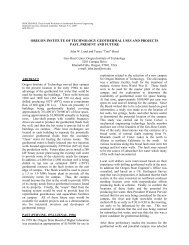
This article presents result of an investigation into<br />
heating fish ponds using geothermal effluent <strong>from</strong> a binary<br />
power generation plant. The investigation was the result of an<br />
inquiry to the Geo-Heat Center and is based on a particular<br />
location–but should be applicable to any location with similar<br />
climate–with appropriate modifications.<br />
GIVEN INFORMATION<br />
4,000 gpm of 205 o F geothermal effluent available<br />
(not suitable for fish habitat).<br />
Minimum temperature -30 o F<br />
Coldest month average temp. 20.6 o F<br />
Coldest month average wind 10 mph<br />
4 ponds, 30 ft x 90 ft x 4 ft average depth<br />
Desired temp. 70-75 o F<br />
<strong>Ponds</strong> plastic lined to prevent seepage with<br />
sand on plastic<br />
Approximately 2 acres of fire suppression ponds<br />
available as bio-filter and source of<br />
oxygenated water adjacent to fish<br />
pond site<br />
25% of fish pond volume exchange with<br />
fire pond water per week<br />
Heating design assumptions, 0 o F, 10 mph wind<br />
Calculated heat loads:<br />
Evaporation 440,850 Btu/hr/pond<br />
Convection 384,910<br />
Radiation 15,470<br />
Total 841,230 x 4 = 3,365,920 Btu/hr<br />
Makeup water @ 25%/wk is a bit more than<br />
evaporation at design heating conditions–and a bit less than<br />
evaporation during summer months.<br />
The proposer presented the idea of heating the ponds<br />
by flowing the 205 o F geothermal effluent through steel pipes<br />
on the pond bottoms or resting the pipes on cement blocks.<br />
After some thought, it was proposed that:<br />
1. Pipes on the bottom would not transfer heat<br />
effectively; since, they would likely be partially<br />
buried and there would be no water circulation<br />
around them. Also, they may rapidly deteriorate the<br />
plastic liners; unless, there was considerable depth of<br />
sand.<br />
18<br />
Gene Culver<br />
Geo-Heat Center<br />
2. Pipes on blocks would promote heat transfer but<br />
present problems in harvest using sein nets.<br />
3. In both 1 and 2, water near the pipes would be much<br />
too hot for the fish, and with only natural convection,<br />
there may be cold spots–promoting crowding in the<br />
desired temperature zones. Also, the hot pipes would<br />
present a danger to workers during the occasional<br />
need to wade in the pond for husbandry purposes.<br />
4. A recirculating system utilizing a heat exchanger to<br />
supply relatively hot water to one end of the pond<br />
with return at the other would also result in a<br />
temperature gradient promoting crowding.<br />
Supplying warm water closer to fishes desired<br />
temperature would require larger more expensive<br />
heat exchanger and/or increased flow rates requiring<br />
larger more expensive pumps and higher operating<br />
costs.<br />
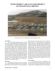
The final proposed system was patterned after ponds<br />
successfully used to grow prawns, mosquito fish and rainbow<br />
trout some 20 years ago at Oregon Institute of Technology.<br />
That system used 135 o F geothermal effluent cascaded <strong>from</strong><br />
one of the campus buildings in the ponds; since, the chemistry<br />
was suitable for the animals.<br />
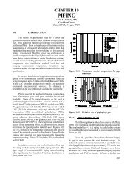
A proposed schematic for the system is shown in<br />
Figure 1. The pumps, controls and heat exchanger could all<br />
be located in a small shelter near the ponds.<br />
Geothermal effluent <strong>from</strong> the power plant is teed off<br />
<strong>from</strong> an existing pipeline between the power plant and<br />
injection well. Peak flow would be 55 gpm. Geothermal<br />
enters the heat exchanger at 205 o F and exits at 76 o F at peak<br />
load conditions. Pressure drop is 0.98 psi. Fluid chemistry<br />
dictates titanium plates in the exchanger. Steel or FRP piping<br />
will be required on the geothermal side of the exchanger.<br />
PVC piping was proposed for the fish pond side of<br />
the system; where, the supply side is at 135 o F. Although PVC<br />
pressure rating is reduced at elevated temperature, at 135 o F it<br />
has 0.26 of its pressure rating at 73 o F or 55 psi in sizes up to<br />
4 inches. Proposed maximum pressure is 15-20 psi.<br />
From pump #1, 108 gpm of about 70 o F water flows<br />
through the heat exchanger and is heated to 135 o F, then<br />
through an adjustable pressure limiting valve, and to the<br />
distribution and diffusion piping. Distribution and diffuser<br />
piping are 2-in. PVC. (More about diffuser hole size and<br />
spacing later.) Pond level is controlled by 4-in. screened<br />
GHC BULLETIN, MARCH 2005
From<br />
injection<br />
pipeline<br />
To injection<br />
pipeline<br />
205 o F<br />
HX<br />
108 gpm<br />
70± o F<br />
Adjustable pressure<br />
reducing valve<br />
39+ o F 8+ gpm<br />
2+ gpm<br />
4 ponds 30' X 90' each<br />
65 o F - 75 o F<br />
Pump<br />
#1<br />
Diffusers 2 per pond<br />
alternate holes 30 o <strong>from</strong> vertical<br />
Sump<br />
Figure 1. Pond layout.<br />
T<br />
Pump<br />
#2<br />
Make up<br />
water<br />
Overflow<br />
Overflow<br />
to fire<br />
pond #2<br />
Fire<br />
Pond<br />
#1<br />
overflow pipes set at the appropriate level and connected to a<br />
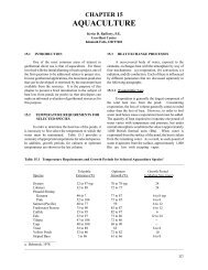
sump via underground PVC. Over flow <strong>from</strong> the sump goes<br />
to a fire pond. Pressure drop across this side of the exchanger<br />
is 3.7 psi.<br />
Makeup water is supplied by pump #2 at a minimum<br />
of 8 gpm (2 gpm per pond) as required for bio-filtering.<br />
Manual balancing valves permit adjusting each pond’s flow.<br />
During summer, this must be increased to allow for higher<br />
evaporation rates.<br />
Geothermal fluid flow through the heat exchanger is<br />
continuous; although, it can be controlled manually by one of<br />
the isolation valves. Pond temperature is sensed in one or<br />
more of the ponds, and controlled by turning pump #1 on or<br />
off. Some experimentation may be required to find the best<br />
location for the sensor. Alternatively, each pond could be<br />
controlled by a temperature sensor and a solenoid valve at<br />
each pond (not shown). When ponds are at temperature and<br />
all solenoid valves closed, a pressure switch at the pump<br />
would turn it off and on again, when one or more solenoid<br />
valves opened.<br />
Flow through the holes in a diffuser pipe is<br />
somewhere between the flow through a short pipe connecting<br />
two tanks with unequal fluid levels and a square edged thick<br />
plate orifice. The general equation is of the form:<br />
Q = CD A 2g P1 − P2<br />
where, C D is an experimental-derived coefficient of discharge<br />
ranging <strong>from</strong> 0.61 for the tanks to about 0.80 for the orifice.<br />
Not finding a good reference for the value of C D in this<br />
configuration and remembering that the people who made<br />
OIT’s diffusers 20 years ago made several trial runs before<br />
GHC BULLETIN, MARCH 2005<br />
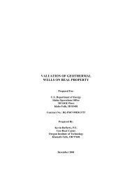
they arrived at the proper size, it was decided to<br />
experimentally determine some flows versus pressure and hole<br />
diameter. The experimental setup is shown in Figure 2. The<br />
results are shown graphically in Figure 3.<br />
For instance, results indicate that at 12 psi at the<br />
pressure valve and allowing for 2 psi loss in piping, 0.607<br />
gpm will flow through a 3/32-dia. Hole, requiring 23 holes per<br />
diffuser pipe to supply 27 gpm per pond at peak load. At 3-ft<br />
hole spacing, 69 ft of diffuser is required. Other combinations<br />
of pressure and hole size result in other numbers of holes and<br />
spacing.<br />
A caveat: when drilling small holes by hand in soft<br />
materials, the holes are almost invariably larger than the drill<br />
size. Our C D values based on the equation above were 0.72-<br />
0.73.<br />
MAJOR COMPONENT COSTS<br />
Water<br />
supply<br />
Adustable pressure<br />
reducing valve<br />
Hole Diameter, Inches<br />
Heat exchanger $5,640<br />
Pump #1 4-hp 780<br />
Pump #2 ½-hp 150<br />
Pressure control valve 450<br />
PVC 2-in, 1,000 ft 310<br />
PVC 4-in., 250 ft 280<br />
8 2-in. PVC valves 200<br />
2" PVC<br />
0.125<br />
0.110<br />
0.094<br />
Pipe wall 0.154"<br />
Certified pressure<br />
gage 0 -15 psi<br />
Hole<br />
46-3/4"<br />
Figure 2. Experiment setup.<br />
10 psi<br />
15 psi<br />
Hose<br />
Water level 46-3/4<br />
inches above holes<br />
0.078<br />
0.25 0.50 0.75<br />
Flow, gpm<br />
1.00 1.25<br />
Figure 3. Experiment results.<br />
Calibrated 5<br />
gallon bucket<br />
19