Oregon Institute of Technology Geothermal Uses and Projects - Past ...
Oregon Institute of Technology Geothermal Uses and Projects - Past ...
Oregon Institute of Technology Geothermal Uses and Projects - Past ...

Create successful ePaper yourself
Turn your PDF publications into a flip-book with our unique Google optimized e-Paper software.
PROCEEDINGS, Thirty-Fourth Workshop on <strong>Geothermal</strong> Reservoir Engineering<br />
Stanford University, Stanford, California, February 9-11, 2009<br />
SGP-TR-187<br />
OREGON INSTITUTE OF TECHNOLOGY GEOTHERMAL USES AND PROJECTS<br />
PAST, PRESENT AND FUTURE<br />
ABSTRACT<br />
<strong>Oregon</strong> <strong>Institute</strong> <strong>of</strong> <strong>Technology</strong> moved their campus<br />
to the present location in the early 1960s to take<br />
advantage <strong>of</strong> the geothermal hot water that could be<br />
used for heating the buildings. Three wells between<br />
1200 <strong>and</strong> 1800 feet (365 <strong>and</strong> 550 m) deep were<br />
drilled, producing 192 o F (89 o C) water at a maximum<br />
flow <strong>of</strong> 600 gpm (38 L/s). There are presently 12<br />
buildings being geothermally heated covering<br />
approximately 763,400 ft 2 (70,900 m 2 ) <strong>of</strong> floor space,<br />
saving approximately $1,000,000 annually in heating<br />
costs. Line-shaft pumps with variable frequency<br />
drives are used to produce the geothermal fluids from<br />
the well, <strong>and</strong> then the hot water is gravity fed to all<br />
buildings on campus. Plate heat exchangers are<br />
located in each building to separate the potentially<br />
corrosive geothermal fluids from the secondary<br />
“clean” water for heating the various rooms. The<br />
geothermal water is finally injected into two injection<br />
wells located approximately 2,050 feet (625 m) from<br />
the production wells. Future plans are to install a 280<br />
kW binary power plant using the existing well water<br />
to provide some <strong>of</strong> the electricity needs for campus.<br />
In addition, a 6,000 foot (1,800 m) deep well is being<br />
drilled to tap into an estimated 300 o F (150 o C)<br />
geothermal resource in the fault system on the east<br />
edge <strong>of</strong> campus. The fluids would be used to power<br />
a 1.5 to 3.0 MWe binary plant to provide all the<br />
electricity needs for campus. Thus, the campus<br />
would become the first in the world to provide 100%<br />
<strong>of</strong> its energy needs from a geothermal resource found<br />
on its property. Finally, the “waste” fluid from the<br />
heating system would be used to provide heat for<br />
experimental greenhouses <strong>and</strong> aquaculture facilities<br />
on campus. All <strong>of</strong> these future uses would be<br />
available for student projects <strong>and</strong> as a demonstration<br />
site for interested investors <strong>and</strong> developers <strong>of</strong><br />
geothermal energy.<br />
PAST (PURVINE, 1974, LIENAU, 1996)<br />
In 1959 the <strong>Oregon</strong> State Board <strong>of</strong> Higher Education<br />
was awarded an appropriation <strong>of</strong> $150,000 for use in<br />
John W. Lund <strong>and</strong> Tonya “Toni” Boyd<br />
Geo-Heat Center, <strong>Oregon</strong> <strong>Institute</strong> <strong>of</strong> <strong>Technology</strong><br />
3201 Campus Drive<br />
Klamath Falls, <strong>Oregon</strong>, 97601, USA<br />
e-mail: john.lund@oit.edu<br />
exploration related to the selection <strong>of</strong> a new campus<br />
for <strong>Oregon</strong> <strong>Institute</strong> <strong>of</strong> <strong>Technology</strong>. The old campus<br />
was a military facility, built for the treatment <strong>of</strong><br />
malaria victims from World War II. These funds<br />
were to be used for the master plant <strong>of</strong> the new<br />
campus <strong>and</strong> for exploration to determine the<br />
availability <strong>of</strong> geothermal water for space heating.<br />
At that time, approximately $100,000 per year was<br />
spent on coal <strong>and</strong> oil heating for the campus. Since<br />
the Board wished this to be a decision based on good<br />
information, a study was made as to the location <strong>of</strong><br />
hot wells, hot springs, faults, <strong>and</strong> other factors useful<br />
in determined the potential location <strong>of</strong> the campus.<br />
This study was carried out by Gene Culver, a<br />
mechanical engineering technology faculty member<br />
<strong>and</strong> later one <strong>of</strong> the founders <strong>of</strong> the Geo-Heat Center.<br />
One <strong>of</strong> the early observations was the existence <strong>of</strong> a<br />
broad series <strong>of</strong> normal faults running from Ft.<br />
Klamath (south <strong>of</strong> Crater Lake) in the north to<br />
Alturas in northern California in the south. At<br />
various locations along this broad fault zone were hot<br />
springs <strong>and</strong> hot water wells. The fault zone seemed<br />
to be the source <strong>of</strong> subsurface hot water which many<br />
<strong>of</strong> the wells had encountered.<br />
Local well drillers were interviewed based on their<br />
experience with drilling geothermal wells in the area.<br />
In addition the <strong>Oregon</strong> State Engineer’s Office was<br />
consulted, <strong>and</strong> based on a US. Geological Survey<br />
map that was in preparation, it indicated that the fault<br />
system in the area consisted on northwest-southeast<br />
trending fracture zone with perpendicular <strong>of</strong>fsets<br />
producing faults in echelon. Finally, to confirm the<br />
locations <strong>of</strong> these faults <strong>and</strong> the potential for<br />
producing hot water, then President Winston Purvine<br />
noticed that for one area being considered for the new<br />
campus, the frost <strong>and</strong> light snowfalls would be<br />
melted <strong>of</strong>f by as early as 8:30 to 9:30 in the morning,<br />
too early to be influenced by the sun. This was<br />
assumed to indicate that the soil was being warmed<br />
by subsurface hot water, <strong>and</strong> was thus the site was a<br />
prime c<strong>and</strong>idate for geothermal drilling.<br />
After these preliminary studies the location for the<br />
geothermal wells <strong>and</strong> potential campus was selected
in the northern edge <strong>of</strong> the City <strong>of</strong> Klamath Falls.<br />
The first well (OIT #1) was drilled in 1959 to a<br />
depth <strong>of</strong> 1,200 feet (366 m) <strong>and</strong> produced 510 gpm<br />
(32 L/s) <strong>of</strong> 78 o F (26 o C) water, which was later used<br />
for the domestic water supply. Moving further west<br />
<strong>and</strong> south within the border <strong>of</strong> the new campus, a<br />
second 1,200-foot (366 m) well (OIT #2) was drilled<br />
OI TI N J-1<br />
Physical<br />
Plant<br />
Co llection Tan k<br />
<strong>and</strong> Booster Pumps<br />
Cornett Hall<br />
Purvine<br />
Hall<br />
OI TINJ-2<br />
Semon<br />
Ha l<br />
South<br />
Ha l<br />
OREGON INS TI TUTE<br />
OF TECHNOLOGY<br />
Libra ry<br />
Owen s<br />
Hall<br />
Sno wm el t<br />
Systems<br />
Stadium<br />
P.E.<br />
Bu ilding<br />
Chiller<br />
Snel Ha ll<br />
D ire ct B ur ied<br />
Tunnel System<br />
in 1960. This was more successful, producing 170<br />
gpm (11 L/s) <strong>of</strong> 176 o F (80 o C) geothermal water.<br />
Two other wells (OIT #5 <strong>and</strong> #6) were later drilled in<br />
1963 in the same area to depths <strong>of</strong> 1,716 feet <strong>and</strong><br />
1,800 feet (523 <strong>and</strong> 549 m) both producing 191 o F<br />
(88 o C) geothermal water at 442 gpm <strong>and</strong> 250 gpm<br />
(28 <strong>and</strong> 16 L/s) <strong>of</strong> geothermal water respectively<br />
(Fig. 1). We later learned that the first or cold water<br />
well was drilled into the up-throw (hanging wall) <strong>of</strong><br />
the normal fault <strong>and</strong> the latter three in the downthrow<br />
(foot wall) <strong>of</strong> the fault block tapping the<br />
outflow zone <strong>of</strong> the geothermal water from the fault<br />
(Fig. 2). At the time, these two deeper wells were<br />
drilled for about $32,000 each or $18 per foot!!! The<br />
wells penetrated at mixture <strong>of</strong> volcanic ash (tuff) <strong>and</strong><br />
diatomaceous earth (locally called “chalk rock”), then<br />
into various layers <strong>of</strong> dense basalt <strong>and</strong> <strong>and</strong>esite,<br />
clayey tuffs, broken lava <strong>and</strong> cinders. The casing<br />
varied from 12 inches (30.5 cm) at the surface to 6<br />
inches (15 cm) at the bottom. The static water level<br />
was at 358 feet (109 m) for the deeper wells. The<br />
original wells were set in a cellar, but were raised to<br />
ground level <strong>and</strong> enclosed in a building in 1970 (Fig.<br />
3).<br />
Figure 1: 1963 photograph <strong>of</strong> Storey Drilling,<br />
completing one <strong>of</strong> the deep geothermal<br />
wells with a cable tool.<br />
Co le ge<br />
Un ion<br />
Residence<br />
Ha ll<br />
D rill site<br />
Figure 2: OIT campus map showing the location <strong>of</strong> wells <strong>and</strong> distribution pipelines.<br />
N<br />
OI T-2<br />
OIT-6<br />
OI T- 1<br />
He at Exc hang er<br />
B ui l di ng<br />
OI T -5
Figure 3: Gene Culver at well #6 showing the 75 hp<br />
(56 kW) motor <strong>and</strong> fluid coupling drive.<br />
The well house is moved for maintenance.<br />
Enclosed lineshaft pumps with the bowls set at<br />
around 550 feet (168 m) with 26 stages are used in<br />
the deeper wells. The original pumps were basically<br />
irrigation well water pumps with direct-coupled<br />
motors, open lineshaft with rubber bearings <strong>and</strong><br />
st<strong>and</strong>ard lateral pumps with bronze bearings <strong>and</strong><br />
impellers. Problems were experienced with broken<br />
line-shafts, motors overheating, pump impellers<br />
loosened on the shaft due to differential expansion<br />
<strong>and</strong> bronze bearings corrosion (Culver, 1994). Since<br />
hot water does not lubricate the bearings well, an oil<br />
drip system had to be installed within an enclosed<br />
lineshaft, <strong>and</strong> allowance had to be made for the<br />
difference in thermal expansion between the line<br />
shaft <strong>and</strong> the impellers – which can be as much as 5.5<br />
inches (14 cm) as the system is heated during the<br />
initial startup (Rafferty <strong>and</strong> Keiffer, 2002). The wells<br />
are pumps with a 75 hp (56 kW) pump, <strong>and</strong> a<br />
variable speed fluid drive to regulate the amount <strong>of</strong><br />
water needed was added in 1970. These were later<br />
replaced with variable frequency drives. The water is<br />
t hen piped into a heat exchanger building where it<br />
enters a settling tank for removal <strong>of</strong> s<strong>and</strong> <strong>and</strong> to meet<br />
peak dem<strong>and</strong>s. From here the water is then gravity<br />
fed into the various buildings on campus. Initially<br />
the geothermal water was used directly in the heating<br />
systems, but due to 2 ppm (2 mg/L) <strong>of</strong> hydrogen<br />
sulfide which attacked the copper <strong>and</strong> solder in the<br />
radiators, isolation plate heat exchangers had to be<br />
installed in each building (Fig. 4) at later date. In the<br />
beginning, the waste water was disposed into a<br />
drainage ditch <strong>and</strong> eventually ended up in Upper<br />
Klamath Lake, about one mile (1.6 km) to the west.<br />
However, based on a 1990 ordinance passed by the<br />
City <strong>of</strong> Klamath Falls, all geothermal water produced<br />
has to be returned to the reservoir. As a result, two<br />
injection wells (INJ #1 <strong>and</strong> INJ #2) were drilled in<br />
1990 to 2,005 <strong>and</strong> 1,675 feet (611 m <strong>and</strong> 510 m) on<br />
t he southwest side <strong>of</strong> campus, approximately 2,050<br />
feet (625 m) from the production wells. These two<br />
well can h<strong>and</strong>le up to 1,400 gpm (88 L/s).<br />
Figure 4: Plate heat exchanger in the College Union<br />
building.<br />
The distribution pipeline around campus initially<br />
consisted <strong>of</strong> steel pipe covered by a rigid foam glass<br />
insulation buried directly in the ground between<br />
buildings. Unfortunately, the metal pipe would<br />
exp<strong>and</strong> <strong>and</strong> contract depending upon flow rate which<br />
changed the supply temperature <strong>of</strong> the geothermal<br />
water, however, the insulation did not. Thus, ground<br />
water leaked into the cracks in the insulation <strong>and</strong><br />
corroded the steel pipe. Oxygen was introduced into<br />
the water from a vent in the storage tank causing<br />
internal corrosion <strong>of</strong> the pipes. Also, since the pipe<br />
was direct buried, it was <strong>of</strong>ten dug up by accident,<br />
since the exact location was not well documented.<br />
Thus, in 1980 a utility tunnel at 6 feet (1.8 m) on a<br />
side was constructed to house most <strong>of</strong> the pipeline, as<br />
well as other utilities on campus (Fig. 5) (Lund <strong>and</strong><br />
Lienau, 1980). Where possible, the tunnel was<br />
located under sidewalks, so any residual heat would<br />
melt snow above. The cost at that time was about<br />
$160/ft. ($525/m). A 312 ton ((1,095 kW) lithiumbromide/water<br />
absorption cycle chiller was installed<br />
on campus in 1980 using the 192 o F (89 o C)<br />
geothermal water to provide cooling in the summer<br />
for about half <strong>of</strong> campus (Lund <strong>and</strong> Lienau, 1980).<br />
Chilled fluid at 44 o F (7 o C) was delivered to the space<br />
cooling system in several <strong>of</strong> the buildings.
Unfortunately, the unit at that time required 240 o F<br />
(116 o C) geothermal water to operate at 100%<br />
efficiency, thus the machine only<br />
produce half <strong>of</strong> the<br />
normal output. For this reason, the require high<br />
geothermal flows (600 gpm – 38 L/s), <strong>and</strong> corrosion<br />
<strong>of</strong> the copper pipes in the generator section, the unit<br />
was replaced with an electric chiller in 1998 (Lienau,<br />
1996).<br />
Figure 5: OIT utility tunnel with geothermal pipe<br />
<strong>and</strong> other utilities.<br />
In the beginning the geothermal water, which could<br />
be pumped up to 750 gpm (47 L/s) using two wells,<br />
heating 440,000 ft<br />
Exchange Building, however, it was never<br />
used <strong>and</strong> removed after a few years. Today, only one<br />
wo being required during<br />
2 (40,900 m 2 ) <strong>of</strong> floor space in six<br />
buildings using either forced air for interior rooms or<br />
base-board hot water for exterior building walls. An<br />
average <strong>of</strong> 2.8 million Btu/hr(3.0 GJ/hr) with a<br />
maximum <strong>of</strong> 24.8 million Btu/hr (26.1 GJ/hr) was<br />
used on campus, costing about $12,000 to $14,000<br />
per year compared with $94,000 to $100,000 per year<br />
on the old campus with conventional fuel. A st<strong>and</strong>by<br />
oil fired boiler from the old campus was installed in<br />
the Heat<br />
well is normally used, with t<br />
extreme cold weather (below 0 o F or -18 o C). The<br />
third well is used for st<strong>and</strong>by, <strong>and</strong> allows<br />
maintenance to be performed without interrupting the<br />
usage.<br />
PRESENT (BOYD, 1999)<br />
Today, geothermal water is produced from three<br />
wells at a temperature <strong>of</strong> 192 o F (89 o C), which are<br />
located in the southeast corner <strong>of</strong> the campus (Fig. 2).<br />
Well water temperature can vary between 192 o <strong>and</strong><br />
196 o F (89 o <strong>and</strong> 91 o C), depending on the pumping rate<br />
<strong>and</strong> location <strong>of</strong> the well. The water is pumped<br />
individually from each well, with a maximum total<br />
flow <strong>of</strong> all the wells at 980 gpm (62 L/s). The water<br />
is then collected in a 4,000-gallon (15 m 3 ) settling<br />
tank in the Heat Exchange building before it is<br />
delivered to each building via gravity through the<br />
distribution system according to the dem<strong>and</strong> on the<br />
system. The settling tank provides the necessary<br />
head for the gravity flow systems <strong>and</strong> allows the fines<br />
from pumping to settle out <strong>of</strong> the water. Due to pipe<br />
failures<br />
from the direct buried distribution system, a<br />
concrete utility tunnel was constructed in 1980.<br />
When new extensions to the tunnel are added,<br />
corrugated galvanized steel culver are used instead <strong>of</strong><br />
concrete, costing about 25% <strong>of</strong> the tunnel cost.<br />
In the original design, the geothermal water was used<br />
directly in each <strong>of</strong> the building mechanical systems.<br />
This “once through” approach eliminated the need for<br />
circulation pumps in the buildings. The direct use <strong>of</strong><br />
the geothermal fluids caused problems due to the<br />
corrosive nature <strong>of</strong> the water. The original chemical<br />
analysis <strong>of</strong> the water failed to consider the effect <strong>of</strong><br />
hydrogen<br />
sulfide <strong>and</strong> ammonia on the copper alloys<br />
used in the mechanical system. There were a number<br />
<strong>of</strong> different types <strong>of</strong> failures<br />
identified that occurred<br />
as a result <strong>of</strong> using the water directly. The more<br />
important ones were:<br />
• Failure <strong>of</strong> the 50/50 tin/lead solder<br />
•<br />
connections,<br />
Rapid failure <strong>of</strong> 1% silver solder,<br />
• Wall thinning <strong>and</strong> perforation <strong>of</strong> copper<br />
tubing was a common occurrence,<br />
• Control valve failure where plug (brass) was<br />
crimped to the stem (stainless steel). The<br />
threaded ones experienced no problems, <strong>and</strong><br />
• Control valve problems associated with<br />
packing leakage.<br />
To address these problems, the geothermal water was<br />
isolated from the building heating systems<br />
using plate<br />
heat<br />
exchangers. The type selected consists <strong>of</strong> 316<br />
stainless steel plates <strong>and</strong> Buna-N gaskets. The heat<br />
exchanger for the campus swimming pool failed due<br />
to the chlorine in the pool water, <strong>and</strong> thus, had to be<br />
replaced with titanium plates.<br />
Some <strong>of</strong> the building systems utilize two loops. In<br />
the case <strong>of</strong> the College Union heat exchanger (Fig. 4)<br />
the first loop provides 1,350,000 Btu/hr (1,420<br />
MJ/hr) using the geothermal water at 100 gpm (6.3<br />
L/s) <strong>and</strong> the building water at 54 gpm (3.4 L/s). The<br />
building water is then circulated through finned-tube<br />
plate heat convectors located along the outside walls<br />
<strong>of</strong> the building. The second loop provides 30,000<br />
Btu/hr (32 MJ/hr)<br />
using geothermal water at 25 gpm<br />
(1.6<br />
L/s) <strong>and</strong> building water at 12 gpm (0.76 L/s).<br />
The building water is then circulated through reheat<br />
coils, which provides heating through a forced-air<br />
system for the interior <strong>of</strong> the building (Lund <strong>and</strong><br />
Lienau, 1980).<br />
The original discharge temperature <strong>of</strong> the waste<br />
effluent was initially quite high (135 o F - 57 o C in<br />
winter <strong>and</strong> 170 o F - 77 o C in summer) when it was<br />
delivered to the drainage ditch. This method
presented a safety hazard <strong>and</strong> was stopped when the<br />
City Ordinance was put into effect in 1990, as<br />
mentioned earlier. Two injection wells were drilled,<br />
that can now h<strong>and</strong>le up to 1,400 gpm (88 L/s). To<br />
reduce the effluent temperature, when Purvine Hall<br />
was constructed, it was designed to use the effluent<br />
from the rest <strong>of</strong> campus. The temperature <strong>of</strong> the<br />
effluent as it enters the building is around 155 o F<br />
(68 o C) <strong>and</strong> leaves at a temperature <strong>of</strong> around 130 o F<br />
(54 o C). The main components <strong>of</strong> this building’s<br />
eating system are a 4,000-gallon (15-m 3 h<br />
) storage<br />
tank, circulating pumps <strong>and</strong> heat exchangers. On the<br />
building heating side, space heating is accomplished<br />
by 54 variable air volume terminals equipped with<br />
hot water coils.<br />
g 50/50 propylene glycol/water temperature is<br />
44 F (62 o The newest additions to the OIT geothermal system<br />
are sections <strong>of</strong> sidewalks, stairs <strong>and</strong> h<strong>and</strong>icap ramps<br />
equipped with geothermal snow melting system. Just<br />
this year, approximately 37,000 ft<br />
C). Each major area has a separate plate<br />
2 (3,400 m 2 ) <strong>of</strong> side<br />
walk <strong>and</strong> driveway systems were installed in front <strong>of</strong><br />
the administration building (Snell Hall) (Fig. 6). The<br />
pipes in the concrete are 5/8- to3/4-inch (1.6- to 1.9cm)<br />
diameter cross-linked polyethylene tubing<br />
(PEX), placed 8 to 10 inches (20 to 25 cm) apart.<br />
The system should be able to maintain a slab surface<br />
temperature <strong>of</strong> 38 o F (3 o C) at -5 o F (-21 o C) air<br />
temperature <strong>and</strong> 10 mph (16 km/h) wind when the<br />
enterin<br />
o<br />
1<br />
heat exchanger <strong>and</strong> the system will activate when the<br />
outside air is 30 o F (-1 o C). The total amount installed<br />
on campus to date covers around 40,400 ft 2 (3,750<br />
m 2 ).<br />
At present twelve buildings are heated totaling<br />
2 2<br />
763,400<br />
ft (70,900 m ). At peak use, the system<br />
provides 16 million Btu/hr (16.9 GJ/h) or a capacity<br />
<strong>of</strong> 4.7 MWt. The annual use is approximately 64.4<br />
billion Btu (67.9 TJ), saving around $1,000,000<br />
annually in heating costs as compared to natural gas.<br />
Figure 6: Installation <strong>of</strong> PEX pipe for the campus<br />
entrance snow melting system in 2008<br />
FUTURE<br />
Five new geothermal projects are being planned <strong>and</strong><br />
some are already underway for campus. These<br />
include: (1) a low-temperature, 280 kW (gross)<br />
binary power plant using the existing well water, (2)<br />
drilling a deep well on campus<br />
to tap an expected<br />
300 o F (150 o C) geothermal water/steam, (3) a 1.5 to<br />
3.0 MWe binary power plant to use the energy from<br />
the deep well, (4) an incubator greenhouse facility,<br />
<strong>and</strong> (5) an incubator aquaculture facility. Each <strong>of</strong><br />
these projects is described in detail below.<br />
Low-temperature power plant<br />
A contract has been signed with United <strong>Technology</strong><br />
Corporation <strong>of</strong> Connecticut to purchase a 280 kW<br />
(gross) binary power plant that can use the 192 o F<br />
(89 o C) geothermal from the existing wells on<br />
campus. We plan to take 15 o F (8 o C) <strong>of</strong>f the top, <strong>and</strong><br />
then the remaining 177 o F (81 o C) is still adequate to<br />
supply the heating needs <strong>of</strong> campus. Maximum flow<br />
would be 600 gpm (38 L/s). In summer <strong>and</strong> warmer<br />
periods, the reject temperature can be reduced to as<br />
low as 150 o F (66 o C), when the campus heating<br />
dem<strong>and</strong> is less. This unit will use a single-cell wet<br />
cooling tower with 70 o F (21 o C) cooling water <strong>and</strong><br />
produce an average net output <strong>of</strong> 85 to 140 kW<br />
depending on the outside temperature <strong>and</strong> humidity.<br />
This would provide approximately 20% <strong>of</strong> the<br />
campus electrical energy dem<strong>and</strong><br />
<strong>and</strong> save $100,000<br />
annually. In addition, the project will serve as a<br />
demonstration site <strong>and</strong> student laboratory, mainly for<br />
students in the new Renewable Energy Engineering<br />
Program. Real time monitoring would be available<br />
for students on our campus <strong>and</strong> at other universities.<br />
Deep well drilling project<br />
To produce additional electrical energy for campus,<br />
we are drilling a deep (up to 6,000 feet – 1,800 m)<br />
geothermal well to intersect the high angle normal<br />
fault on the east side <strong>of</strong> campus. The geothermally<br />
heated fluid upwelling along the fault is already<br />
tapped by our existing geothermal wells. Based on<br />
su rface water geochemistry (analyzing the existing<br />
well water) researchers predicts that approximately<br />
300 o F (150 o C) geothermal fluids exist at depth.<br />
Thus, we hope to drill into the fault <strong>and</strong> produce up<br />
to 1,500 gpm (95 L/s) <strong>of</strong> hot fluid to supply a 1.5<br />
MWe to 3.0 MWe power plant, depending upon the<br />
temperature <strong>and</strong> flow rate <strong>of</strong> the fluid.<br />
In 2008 we contracted for <strong>and</strong> completed a reflection<br />
seismic survey <strong>of</strong> campus to better locate the fault<br />
<strong>and</strong> thus located the drilling site (approximately 64<br />
2.2 lb – 1 kg dynamite charges at 18 feet (6 m) depth<br />
were set <strong>of</strong>f on campus <strong>and</strong> surrounding property to<br />
bounce<br />
energy waves <strong>of</strong>f subsurface structures). The<br />
seismic<br />
survey can be viewed at
http://geoheat.oit.edu/oit/Sesimic_Final _Report.pdf.<br />
This investigation determined the optimum drilling<br />
target at about the 3,000 to 4,000 foot (900 to 1,040<br />
m) depth (Fig. 7). The drill site is in the southeast<br />
corner <strong>of</strong> the upper parking lot.<br />
Proposed<br />
well location<br />
Figure 7: East-west seismic pr<strong>of</strong>ile showing the fault<br />
<strong>and</strong> fracture zone with the proposed deep<br />
well location.<br />
As part <strong>of</strong> the USDOE grant requirements, we<br />
completed an environmental assessment (EA) under<br />
the NEPA requirements. The final EA can be viewed<br />
at http://geoheat.oit.edu/oit/OIT-Deep-<strong>Geothermal</strong>-<br />
Well-<strong>and</strong>-Power-Plant-Project-FEA_0908.pdf.<br />
A Request for Proposal (RFP) for drilling the deep<br />
well was prepared <strong>and</strong> a contract was awarded to<br />
ThermaSource, Inc. <strong>of</strong> Santa Rosa in December<br />
2008. Drilling for the 30-foot (9-m) deep surface<br />
casing (conductor pipe) <strong>of</strong> 30 inch (76 cm) was<br />
completed in early January by a local contractor.<br />
ThermaSource had their drilling rig on site <strong>and</strong><br />
started their drilling by the 2 nd week <strong>of</strong> January 2009<br />
(Fig. 8). Today they have drilled to 300 feet (91 m)<br />
<strong>and</strong> set <strong>and</strong> cemented a 20-inch (51-cm) diameter<br />
casing. They are now drilling the 2,500-ft (760 m)<br />
hole for the 13-3/8-inch (34-cm) casing. The well<br />
will be finished with a 9-5/8-inch (24-cm) diameter<br />
production casing. Deviated drilling may be required<br />
to better intersect <strong>and</strong> tap the fractured fault zone.<br />
We will determine this course <strong>of</strong> drilling when we<br />
reach approximately 3,000 feet (914 m). We hope to<br />
have the well completed by February <strong>and</strong> flow tested<br />
by March 2009. The only problem that we have<br />
experience on campus is complaints by student due to<br />
lack <strong>of</strong> parking, as the drill site has temporally taken<br />
out about 75 parking spaces. Noise has not been a<br />
problem. Funding for the drilling is provided by the<br />
U.S. Department <strong>of</strong> Energy <strong>and</strong> the <strong>Oregon</strong><br />
University System.<br />
Figure 8: ThermaSource drilling rig on the OIT<br />
campus.<br />
High Temperature Power Plant<br />
A 1.5 to 3.0 MWe power plant (gross) would be<br />
design to use the fluids from the deep well. It will<br />
probably be on a binary type (organic Rankine cycle<br />
using a secondary low boiling point hydrocarbon)<br />
supplying around 1.2 MWe to 2.5 MWe (net) to<br />
campus, enough to cover all <strong>of</strong> the electric energy<br />
requirements<br />
plus some to sell to the grid. If higher<br />
temperatures<br />
are encountered, then a flash steam type<br />
<strong>of</strong> plant would be installed. This would save the<br />
campus round $500,000 per year.<br />
Once the well is completed <strong>and</strong> tested, <strong>and</strong> we know<br />
the temperature, flow rate <strong>and</strong> mineral content, the<br />
power plant will be designed, ordered <strong>and</strong> installed<br />
through a competitive solicitation (RFP). This<br />
should take approximately six month to a year, <strong>and</strong><br />
thus, the plant will be ordered <strong>and</strong> on site sometime<br />
in late 2009 or early 2010, <strong>and</strong> operational soon after<br />
that.<br />
$14 million; however, the “waste water” from<br />
the power plant at around 200 o F (93 o The cost <strong>of</strong> the well <strong>and</strong> 1.5 MWe power plant would<br />
be around $9.0 million, <strong>and</strong> the 3.0 MWe power plant<br />
around<br />
C), could then<br />
be sold to adjacent property owners<br />
or used to<br />
supplement the existing <strong>and</strong> new OIT heating<br />
dem<strong>and</strong>s, generating additional income or savings,<br />
along with selling excess electrical energy to the grid.<br />
The site would also become a demonstration site <strong>and</strong><br />
student laboratory with real time monitoring<br />
available. Funding for the projects comes from a US<br />
Department <strong>of</strong> Energy grant, <strong>and</strong> from <strong>Oregon</strong> State<br />
bonds <strong>and</strong> grants. Additional support may come<br />
from the Energy Trust <strong>of</strong> <strong>Oregon</strong> <strong>and</strong> the Climate<br />
Trust.
Incubator Greenhouse Facility<br />
We are proposing to construct two geothermally<br />
heated greenhouses on campus. The greenhouses<br />
would be 100 by 60 feet (31 by 18 m) covering 6,000<br />
ft 2 (560 m 2 ) <strong>and</strong> designed to grow a variety <strong>of</strong> cut<br />
flowers, potted plants <strong>and</strong> vegetables. Different<br />
heating <strong>and</strong> cooling systems would be provided to<br />
each greenhouse as a research <strong>and</strong> demonstration<br />
project. All heating <strong>and</strong> cooling in the greenhouse<br />
would be monitored <strong>and</strong> controlled by computer.<br />
The greenhouses would be an incubator facility for<br />
interested investors/developers to test the feasibility<br />
<strong>of</strong> growing their crop in a controlled environment<br />
utilizing geothermal energy. The facility would also<br />
provide research projects for students on campus <strong>and</strong><br />
for the local agricultural programs at the community<br />
college <strong>and</strong> rural high school. The facility would<br />
require around 140 o F (60 o C) <strong>and</strong> 60 gpm (4 L/s), that<br />
could easily be met from out existing geothermal<br />
wells, mainly by cascading the effluent water from<br />
the campus heating system.<br />
Incubator Aquaculture Facility<br />
We are also proposing to construct two geothermally<br />
heated outdoor aquaculture ponds <strong>and</strong> a covered<br />
nursery tank facility on campus. The outdoor ponds<br />
would be 100 by 30 feet (31 by 9 m) <strong>of</strong> 3,000 ft 2 (280<br />
m 2 ) <strong>and</strong> the indoor covered facility would be <strong>of</strong><br />
greenhouse construction 100 by 60 feet (31 by 19 m)<br />
2 2<br />
covering 6,000 ft (560 m ). Different heating<br />
systems would be provided to each pond as a<br />
research <strong>and</strong> demonstration project. The covered<br />
facility would consist <strong>of</strong> a series <strong>of</strong> fiberglass tanks,<br />
heated by the geothermal water. All heating systems<br />
would be monitored <strong>and</strong> controlled by computer.<br />
Various fish species, hard-shell aquatic species <strong>and</strong><br />
even various algae could be tested. Effluent water<br />
from the campus geothermal heating system at<br />
around 140<br />
cubator facility for<br />
o F (60 o C) <strong>and</strong> 150 gpm (9 L/s) would be<br />
required, that could easily be met by cascading. The<br />
facility<br />
would provide an in<br />
potential developer/investors <strong>and</strong> also be used as a<br />
laboratory for campus students.<br />
CONCLUSIONS<br />
The campus was built on its present location mainly<br />
to take advantage <strong>of</strong> the geothermal energy that is<br />
provided by water moving up along the high-angle<br />
normal fault on the east side <strong>of</strong> campus. Using three<br />
geothermal wells that tap a 192 o F (89 o C) fluid <strong>and</strong><br />
are pumped up to 600 gpm (39 L/s), provides an<br />
installed capacity <strong>of</strong> 3.8 MWt <strong>and</strong> annual supply <strong>of</strong><br />
64.4 billion Btu (67.9 TJ), saving an estimate<br />
$1,000,000/yr in heating<br />
costs.<br />
When the deep well is completed <strong>and</strong> the 1.5 to 3.0<br />
MWe<br />
power plant is up <strong>and</strong> running on campus,<br />
<strong>Oregon</strong><br />
<strong>Institute</strong> <strong>of</strong> <strong>Technology</strong> will be the first<br />
campus in the world to supply all its heating <strong>and</strong><br />
electrical<br />
energy from a geothermal resource directly<br />
under<br />
campus. We will be 100% green <strong>and</strong> a<br />
showplace for all forms <strong>of</strong> geothermal utilization.<br />
Along<br />
with our Renewable Energy Engineering<br />
Program<br />
<strong>and</strong> technical assistance provided by the<br />
Geo-Heat<br />
Center (http://geoheat.oit.edu), we will be a<br />
leader for renewable geothermal energy utilization.<br />
R EFERENCES<br />
Boyd, T. L., 1999. The <strong>Oregon</strong> <strong>Institute</strong> <strong>of</strong><br />
<strong>Technology</strong> <strong>Geothermal</strong> Heating System – Then<br />
<strong>and</strong> Now, Geo-Heat Center Quarterly Bulletin,<br />
Vol. 20, No. 1, (March), Klamath Falls, OR, pp.<br />
10-13.<br />
Culver,<br />
G., 1994. Results <strong>of</strong> Investigations <strong>of</strong> Failure<br />
<strong>of</strong> <strong>Geothermal</strong> Direct-Use Well Pumps.<br />
Technical Report prepared for U.S. Department<br />
<strong>of</strong> Energy, Grant No. DE-FG07-90ID 13040,<br />
Geo-Heat Center, Klamath Falls, OR, 33 p.<br />
Lienau,<br />
P. J., 1996. OIT <strong>Geothermal</strong> System<br />
Improvements, Geo-Heat Center Quarterly<br />
Bulletin, Vol. 17, No. 3 (August), Klamath Falls,<br />
OR, pp. 24-28.<br />
Lund, J. W., <strong>and</strong> P. J.Lienau, 1980. New <strong>Geothermal</strong><br />
Construction on the OIT Campus, Geo-Heat<br />
Center Quarterly Bulletin, Vol. 5, No. 3.<br />
(September), Klamath Falls, OR, pp. 21-23.<br />
Purvine, W. D., 1974. Utilization <strong>of</strong> Thermal Energy<br />
at <strong>Oregon</strong> <strong>Institute</strong> <strong>of</strong> <strong>Technology</strong>, Klamath<br />
Falls, <strong>Oregon</strong>, Proceedings <strong>of</strong> the International<br />
Conference on <strong>Geothermal</strong> Energy for Industrial,<br />
Agricultural <strong>and</strong> Commercial-Residential <strong>Uses</strong>,<br />
<strong>Oregon</strong> <strong>Institute</strong> <strong>of</strong> <strong>Technology</strong>, Klamath Falls,<br />
OR, pp. 179-191.<br />
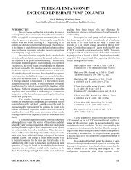
Rafferty, K., <strong>and</strong> S. Keiffer, 2002. Thermal<br />
Expansion in Enclosed Lineshaft Pump<br />
Columns, Geo-Heat Center Quarterly Bulletin,<br />
Vol. 23, No. 2 (June), Klamath Falls, OR, pp.<br />
11-15.