
Create successful ePaper yourself
Turn your PDF publications into a flip-book with our unique Google optimized e-Paper software.
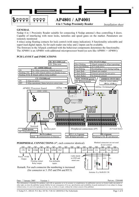
<strong>AP4801</strong> / <strong>AP4001</strong><br />
4 in 1 Nedap Proximity Reader<br />
GENERAL<br />
Nedap 4 in 1 Proximity Reader suitable for connecting 4 Nedap antenna’s thus controlling 4 doors.<br />
Capable of interfacing with most locks, turnstiles and speed gates on the market. Parameters are<br />
remotely monitored<br />
4 relays using floating contacts for lock control (with status indication). 8 functionality selectable and<br />
supervised digital inputs. So for each reader one relay and 2 inputs can be available.<br />
The firmware in the AEpack combined with the behaviour components determines the functionality.<br />
The <strong>AP4801</strong> is an <strong>AP4001</strong> with additional microprocessor board (so acts like AP8001 + <strong>AP4001</strong>)<br />
PCB LAYOUT and INDICATIONS<br />
BE: BUS ERR (red)<br />
ON<br />
AE: ADDR ERR(red)<br />
Bus error<br />
ON No AEpu connection (AEpack passive)<br />
Flashing 5 Hz No valid AEpack address (or already in use)<br />
Flashing 20 Hz AEpack address being modified<br />
CE: CB ERR(red)<br />
ON AEpu not active<br />
OFF AEpu operational, Status led gives correct state<br />
<strong>AP4801</strong> Processor board<br />
<strong>AP4001</strong> / <strong>AP4801</strong><br />
LINK (green)<br />
ON Ethernet present<br />
Rx/Tx (yellow)<br />
Blink Communication on Ethernet<br />
Floating contact<br />
Relay output<br />
Free definable<br />
inputs<br />
POW: POWER (green)<br />
ON Power present<br />
RY2, 1, 4, 3 (green)<br />
ON Output activated<br />
Installation sheet<br />
STS: STATUS (blue)<br />
Slow blinking AEpack assigned to AEpu (operating)<br />
Very fast blinking ALT mode active<br />
Fast blinking Downloading or error during loading<br />
1 short flash AEpack not coupled<br />
2 short flashes Firmware present but not active<br />
3 short flashes No firmware present<br />
ADDRESS SWITCHES<br />
Turn for correct address<br />
(99 for AP48xx)<br />
ALT mode button<br />
ID1..4 (green)<br />
Flashing 0,5 Hz Card detected<br />
PERIPHERAL CONNECTIONS (4*, each connector identical)<br />
Blanked connectors are not used<br />
do not connect<br />
1 2 3 4 5 6 7 8 9 10 11 12 13 14 15 16<br />
+5V NC COM NO IN1 GND IN2 ANT GND UL GND NA GND<br />
Power +5VDC<br />
Output<br />
Network<br />
Battery<br />
RY2<br />
RY2<br />
AEbus<br />
RY1<br />
RY1<br />
CGND<br />
CL<br />
CH<br />
~ -<br />
~ +<br />
Date : 7 January 2005 Version: 1<br />
Part.no.: 5266440<br />
This information is furnished for guidance, and with no guarantee as to its accuracy or completeness; its publication conveys no licence under any patent or<br />
other right, nor does the publisher assume liability for any consequence of its use; specifications and availability of goods mentioned in it are subject to change<br />
without notice; it is not to be reproduced in any way, in whole or in part, without the written consent of the publisher.<br />
© Nedap N.V., IDEAS P.O. Box 103 NL-7140 AC GROENLO The Netherlands Page 1 of 4<br />
ON<br />
Tamper switch<br />
BE<br />
AE<br />
CE<br />
RY4<br />
POW<br />
STS<br />
ID1<br />
ID2<br />
RY3<br />
ID3<br />
ID4<br />
1 3<br />
2 4<br />
Service port Peripheral connections (4*)<br />
Remark: For each connector the numbering is increased<br />
(for connector nr 3: IN5 and IN6 and RY3)<br />
Cable shield<br />
to GND and<br />
metal case<br />
ANTENNA COIL<br />
RY4<br />
RY3<br />
UL GREEN<br />
AEbus Termination<br />
UL GND NA<br />
NA RED<br />
Antenna: E.g. RefleXS 130<br />
®
Relay contacts are dry contacts. If supply voltage is needed,<br />
make interconnections between Power Supply and relay<br />
All inputs are supervised (software<br />
selectable). See diagram for connections.<br />
NA and UL led: UL – NA: 5V, R=220 included, LED cathode to GND.<br />
COM<br />
Power<br />
<strong>AP4801</strong> / <strong>AP4001</strong><br />
NC<br />
Door lock<br />
Connect protection diode as near as<br />
possible to electrical terminals of lock<br />
CONNECTIONS<br />
AP4xxx series are NOT hot-swappable, so changing or adding these AEpacks or connections may<br />
only be done when Power is switched OFF.<br />
AP4XXX connector<br />
Cables outside housing: Use always shielded cables and connect shield to<br />
top view<br />
metal case.<br />
© Nedap N.V. <strong>AP4801</strong> / <strong>AP4001</strong> Installation sheet Page 2 of 4<br />
GND<br />
POWER CONNECTIONS<br />
AP4xxx can get the power from the AEbus (check maximum power) or from<br />
separate Power Supply. Power for Lock must be connected external to Relay<br />
(see above). Connections: + ~ and - ~ (both AC and DC).<br />
NETWORK CONNECTION (AP48xx only)<br />
Network is connected using the RJ-45 network connector. (No indication 10/100 Mbit)<br />
SERVICE CONNECTOR (AP48xx only)<br />
For configuration the serial port on 9 pin SUB-D connector<br />
is used. Configuration is done by using hyperterminal. See<br />
AEOS installation manual for more information.<br />
SYSTEM CONFIGURATIONS (how to connect AP4xxx<br />
and AEpacks)<br />
AP4xxx only<br />
Total bus length: max 1000m. (BitRate: 1)<br />
AP4xxx with single AEpacks AX2002<br />
NO<br />
AP48xx Function SUB-D<br />
2 (Tx) Rx (Receive data)<br />
5 (GND) GND<br />
3 (Rx) Tx (Transmit data)<br />
7 (CTS) Clear to send (Output)<br />
8 (RTS) Request to send (Input)<br />
Total bus length: max 300m. (BitRate: 0)<br />
Total bus length: max 5m. (BitRate: 0)<br />
Remark: If AP4xxx is only connected and total cable length >300 m, then BitRate of AP48xx must<br />
be set to 1.(AEmon: View – Hardware – AEbusConfiguration - BitRate).<br />
If single AEpacks are connected then BitRate must be 0. (Default setting is 0.)<br />
INx<br />
GND<br />
AEBUS CONNECTIONS<br />
AEbus connections must always be to the identical point of the other AEpack or AX2002. The<br />
AP4xxx has a single AEbus connector, so two cables must be mounted on one connector. (For<br />
detailed connections see next page.)<br />
R=4K7<br />
R= 4K7<br />
Contact<br />
5V<br />
GND<br />
R=220<br />
+<br />
-<br />
UL/NA<br />
+ ~<br />
- ~<br />
CH<br />
CL<br />
AP4xxx with single AEpacks<br />
CGND<br />
Total bus length: max 5m. (BitRate: 0)<br />
Single AEpacks with AP4xxx<br />
rear view
+ ~<br />
- ~<br />
CH<br />
CL<br />
CGND<br />
1 AP4xxx to AP4xxx<br />
AEbus connectors<br />
rear view<br />
AP4xxx n AP4xxx<br />
+1<br />
Remark: If Power is locally supplied on the next AP4xxx connect only CH, CL and CGND.<br />
<strong>AP4801</strong> / <strong>AP4001</strong><br />
Going outside AEpacks housing: shielded cable must be used; CH and CL must be one twisted pair.<br />
From other pair one conductor is used for CGND. Shield must be connected to metal housing, (to<br />
which also the metal mounting rail of the AEpacks is connected). (CH CH and CL CL)<br />
Attention: The communication line must be terminated correctly, see chapter Termination Switch.<br />
TERMINATION SWITCH<br />
The AEbus must be terminated correctly at the first and the last<br />
AEpack. For this purpose the switch beside the AEbus connector is<br />
used. See text at switch for correct ON and OFF position. See figure<br />
below, also for combination with AX2002.<br />
Resistor ON for<br />
first and last<br />
AP4xxx first<br />
+ ~<br />
- ~<br />
CH<br />
CL<br />
CGND<br />
+ ~<br />
- ~<br />
CH<br />
CL<br />
CGND<br />
2 AP4xxx to AEpacks<br />
+ ~<br />
- ~<br />
CH<br />
CL<br />
CGND<br />
AEbus connectors<br />
rear view<br />
VIN<br />
GND<br />
CH<br />
CL<br />
CGND<br />
AP4xxx n AEpack n+1<br />
AP4xxx between<br />
ON OFF<br />
OFF<br />
+ ~<br />
- ~<br />
CH<br />
CL<br />
CGND<br />
Cable shield to earth<br />
on both sides<br />
Resistor OFF for<br />
all between<br />
+ ~<br />
- ~<br />
CH<br />
CL<br />
CGND<br />
3 AP4xxx to AX2002<br />
+ ~<br />
- ~<br />
CH<br />
CL<br />
CGND<br />
+ ~<br />
- ~<br />
AEbus connector<br />
top view<br />
AEbus connectors<br />
rear view<br />
AP4xxx n AX2002<br />
ADDRESS SETTING<br />
AP48xx: address must be 99 (AP48xx only).<br />
The Address switch gives address of AEpack. Left: units of 10, right: units of 1.<br />
BUS ERR and ADDR ERR LED’s indicates address status. Address valid: both LED’s must be off.<br />
New installation: select free address; Replacing AEpack: use the same address.<br />
The address is used for configuring the AEpack (software settings) so write it down.<br />
Address 00 is used to set the AEpack off-line (isolation of AEpack).<br />
© Nedap N.V. <strong>AP4801</strong> / <strong>AP4001</strong> Installation sheet Page 3 of 4<br />
OFF<br />
CH<br />
CL<br />
CGND<br />
AEbus termination<br />
switch<br />
ON<br />
Resistor ON for<br />
first and last<br />
AX2002 AX2002 last<br />
OFF ON<br />
AEbus (extender) connectors<br />
rear view
<strong>AP4801</strong> / <strong>AP4001</strong><br />
BATTERY (AP48xx only)<br />
Battery must be enabled by removing plastic isolator that is put between its contacts. (Battery is used<br />
for real time clock on AP48xx)<br />
TAMPER SWITCH<br />
Tamper switch can be read by the software and thus generating an alarm if enclosure is opened.<br />
AEPACK LOCAL TEST (ALT MODE)<br />
ALT mode allows a simple test of the basic functions of AEpack. Switching on/off ALT mode is<br />
logged on server!<br />
Start ALT mode: Press ALT button more than 3 seconds. Status LED blinks fast.<br />
Back to normal operation: No action in ALT mode during 15 minutes or ALT switch pressing again<br />
for 3 seconds. After returning to operation mode the situation from before starting the ALT mode is<br />
restored.<br />
ALT mode for AP4x07: Short activating button will cause a new test situation, tests will loop around:<br />
1 Reads card: ID led blinks, UL led acts like ID led, activates relay 1<br />
2 Relay 1 ON NA and UL led ON, UL led flashes during reading card<br />
3 Relay 1 OFF<br />
Steps 1,2,3 are repeated for all four outputs.<br />
FIRMWARE<br />
Pay attention that the firmware loaded in AEpack and AEpu determines functionality and protocols.<br />
SPECIFICATIONS <strong>AP4801</strong> (Product nr. 9842640) <strong>AP4001</strong> (Product nr. 9842500)<br />
Dimensions: 230 x 345 x 70 mm Weight: ± 900 gr<br />
Power input: 10 – 35VDC 10 – 25VAC <strong>AP4801</strong>: Min. AEpack power consumption: 300mA@24VDC / 600mA@12VDC<br />
<strong>AP4001</strong>: Min. AEpack power consumption: 200mA@24VDC / 300mA@12VDC<br />
Environment: Temperature: Operating: 0 – 55 °C, Storage: -30 – 65 °C Relative humidity: 10 – 93% non condensing<br />
Lock supply: External Additional supply: +5VDC ±10% max 100mA<br />
Inputs: 8: Intended for dry contact or open collector, optional supervised (software selectable)<br />
Outputs: 4: Dry contact (normally open, common, normally closed).<br />
Contact ratings: (Suitable for switching inductive loads, clean relay contacts)<br />
Switching voltage: 24VAC, 48VDC<br />
Continuous current and switching current: 6A (AC and DC)<br />
Contact lifetime: min 500.000 times at given ratings<br />
Indications: 4* UL and NA led for antenna: max 20 mA<br />
Communication: AP48xx: Ethernet: UTP 100/10 Mbps (auto detection)<br />
Service port RS232 (Rx, Tx, GND, RTS, CTS)<br />
Battery: CR2032 (lifetime 2 years if no power present)<br />
Antennas: Only antenna’s with adjustment included can be used, otherwise add adjustment box<br />
UL and NA led for antenna: max 20 mA, (5VDC; R=220E)<br />
Detection distance: RefleXS260 and UniXS card: max 30 cm, RefleXS260 and XM card: 40 cm<br />
CABLE SPECIFICATIONS<br />
Inputs: 2 x 0,25mm², max cable length: 100 meter, cable capacity