carbon dioxide capture and storage carbon dioxide capture and ...
carbon dioxide capture and storage carbon dioxide capture and ...
carbon dioxide capture and storage carbon dioxide capture and ...

You also want an ePaper? Increase the reach of your titles
YUMPU automatically turns print PDFs into web optimized ePapers that Google loves.
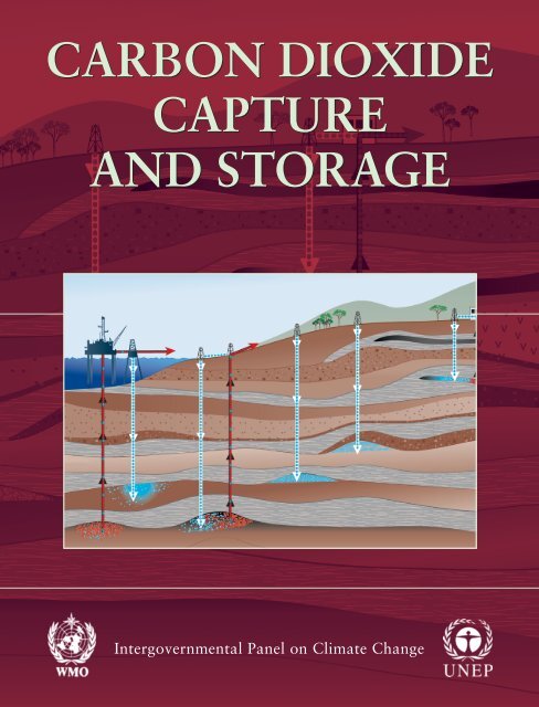
CARBON DIOXIDE<br />
CAPTURE<br />
AND STORAGE<br />
Intergovernmental Panel on Climate Change
IPCC Special Report<br />
Carbon Dioxide Capture <strong>and</strong> Storage<br />
Summary for Policymakers<br />
A Special Report of Working Group III<br />
of the Intergovernmental Panel on Climate Change<br />
This summary, approved in detail at the Eighth Session of IPCC Working Group III<br />
(Montreal, Canada, 22-24 September 2005), represents the formally agreed statement of<br />
the IPCC concerning current underst<strong>and</strong>ing of <strong>carbon</strong> <strong>dioxide</strong> <strong>capture</strong> <strong>and</strong> <strong>storage</strong>.<br />
Based on a draft by:<br />
Juan Carlos Abanades (Spain), Makoto Akai (Japan), Sally Benson (United States), Ken Caldeira<br />
(United States), Heleen de Coninck (Netherl<strong>and</strong>s), Peter Cook (Australia), Ogunlade Davidson<br />
(Sierra Leone), Richard Doctor (United States), James Dooley (United States), Paul Freund (United<br />
Kingdom), John Gale (United Kingdom), Wolfgang Heidug (Germany), Howard Herzog (United States),<br />
David Keith (Canada), Marco Mazzotti (Italy <strong>and</strong> Switzerl<strong>and</strong>), Bert Metz (Netherl<strong>and</strong>s), Leo Meyer<br />
(Netherl<strong>and</strong>s), Balgis Osman-Elasha (Sudan), Andrew Palmer (United Kingdom), Riitta Pipatti (Finl<strong>and</strong>),<br />
Edward Rubin (United States), Koen Smekens (Belgium), Mohammad Soltanieh (Iran), Kelly (Kailai)<br />
Thambimuthu (Australia <strong>and</strong> Canada)
Contents<br />
Summary for Policymakers<br />
What is CO 2 <strong>capture</strong> <strong>and</strong> <strong>storage</strong> <strong>and</strong> how could it contribute to mitigating climate change? ........................................................ 3<br />
What are the characteristics of CCS? .............................................................................................................................................. 5<br />
What is the current status of CCS technology? ............................................................................................................................... 5<br />
What is the geographical relationship between the sources <strong>and</strong> <strong>storage</strong> opportunities for CO 2 ? .................................................... 8<br />
What are the costs for CCS <strong>and</strong> what is the technical <strong>and</strong> economic potential? ........................................................................... 10<br />
What are the local health, safety <strong>and</strong> environment risks of CCS? ................................................................................................ 12<br />
Will physical leakage of stored CO 2 compromise CCS as a climate change mitigation option? .................................................. 14<br />
What are the legal <strong>and</strong> regulatory issues for implementing CO 2 <strong>storage</strong>? .................................................................................... 15<br />
What are the implications of CCS for emission inventories <strong>and</strong> accounting? .............................................................................. 15<br />
What are the gaps in knowledge? .................................................................................................................................................. 15
What is CO <strong>capture</strong> <strong>and</strong> <strong>storage</strong> <strong>and</strong> how could it<br />
contribute to mitigating climate change?<br />
1. Carbon <strong>dioxide</strong> (CO 2 ) <strong>capture</strong> <strong>and</strong> <strong>storage</strong> (CCS) is a<br />
process consisting of the separation of CO 2 from industrial<br />
<strong>and</strong> energy-related sources, transport to a <strong>storage</strong> location<br />
<strong>and</strong> long-term isolation from the atmosphere. This report<br />
considers CCS as an option in the portfolio of mitigation<br />
actions for stabilization of atmospheric greenhouse gas<br />
concentrations.<br />
Other mitigation options include energy efficiency<br />
improvements, the switch to less <strong>carbon</strong>-intensive fuels,<br />
nuclear power, renewable energy sources, enhancement of<br />
biological sinks, <strong>and</strong> reduction of non-CO 2 greenhouse gas<br />
emissions. CCS has the potential to reduce overall mitigation<br />
costs <strong>and</strong> increase flexibility in achieving greenhouse gas<br />
emission reductions. The widespread application of CCS<br />
would depend on technical maturity, costs, overall potential,<br />
diffusion <strong>and</strong> transfer of the technology to developing<br />
countries <strong>and</strong> their capacity to apply the technology, regulatory<br />
aspects, environmental issues <strong>and</strong> public perception (Sections<br />
1.1.1, 1.3, 1.7, 8.3.3.4).<br />
2. The Third Assessment Report (TAR) indicates that no<br />
single technology option will provide all of the emission<br />
reductions needed to achieve stabilization, but a portfolio<br />
of mitigation measures will be needed.<br />
Summary for Policymakers<br />
Most scenarios project that the supply of primary energy<br />
will continue to be dominated by fossil fuels until at least<br />
the middle of the century. As discussed in the TAR, most<br />
models also indicate that known technological options 1 could<br />
achieve a broad range of atmospheric stabilization levels<br />
but that implementation would require socio-economic <strong>and</strong><br />
institutional changes. In this context, the availability of<br />
CCS in the portfolio of options could facilitate achieving<br />
stabilization goals (Sections 1.1, 1.3).<br />
What are the characteristics of CCS?<br />
3. Capture of CO 2 can be applied to large point sources.<br />
The CO 2 would then be compressed <strong>and</strong> transported for<br />
<strong>storage</strong> in geological formations, in the ocean, in mineral<br />
<strong>carbon</strong>ates 2 , or for use in industrial processes.<br />
Large point sources of CO 2 include large fossil fuel or<br />
biomass energy facilities, major CO 2 -emitting industries,<br />
natural gas production, synthetic fuel plants <strong>and</strong> fossil<br />
fuel-based hydrogen production plants (see Table SPM.1).<br />
Potential technical <strong>storage</strong> methods are: geological <strong>storage</strong> (in<br />
geological formations, such as oil <strong>and</strong> gas fields, unminable<br />
coal beds <strong>and</strong> deep saline formations 3 ), ocean <strong>storage</strong> (direct<br />
release into the ocean water column or onto the deep seafloor)<br />
<strong>and</strong> industrial fixation of CO 2 into inorganic <strong>carbon</strong>ates.<br />
This report also discusses industrial uses of CO 2 , but this<br />
is not expected to contribute much to the reduction of CO 2<br />
Table SPM.1. Profile by process or industrial activity of worldwide large stationary CO2 sources with emissions of more than 0.1 million<br />
tonnes of CO2 (MtCO2 ) per year.<br />
Process Number of sources Emissions<br />
(MtCO yr-1 Fossil fuels<br />
)<br />
Power 4,942 10,539<br />
Cement production 1,175 932<br />
Refineries 638 798<br />
Iron <strong>and</strong> steel industry 269 646<br />
Petrochemical industry 470 379<br />
Oil <strong>and</strong> gas processing Not available 50<br />
Other sources<br />
Biomass<br />
90 33<br />
Bioethanol <strong>and</strong> bioenergy 303 91<br />
Total 7,887 1 ,466<br />
1 “Known technological options” refer to technologies that exist in operation or in the pilot plant stage at the present time, as referenced in the mitigation scenarios<br />
discussed in the TAR. It does not include any new technologies that.will require profound technological breakthroughs. Known technological options are<br />
explained in the TAR <strong>and</strong> several mitigation scenarios include CCS<br />
2 Storage of CO2 as mineral <strong>carbon</strong>ates does not cover deep geological <strong>carbon</strong>ation or ocean <strong>storage</strong> with enhanced <strong>carbon</strong>ate neutralization as discussed in<br />
Chapter 6 (Section 7.2).<br />
3 Saline formations are sedimentary rocks saturated with formation waters containing high concentrations of dissolved salts. They are widespread <strong>and</strong> contain<br />
enormous quantities of water that are unsuitable for agriculture or human consumption. Because the use of geothermal energy is likely to increase, potential<br />
geothermal areas may not be suitable for CO2 <strong>storage</strong> (see Section 5.3.3).
4 Summary for Policymakers<br />
Figure SPM.1. Schematic diagram of possible CCS systems showing the sources for which CCS might be relevant, transport of CO 2 <strong>and</strong><br />
<strong>storage</strong> options (Courtesy of CO2CRC).<br />
emissions (see Figure SPM.1) (Sections 1.2, 1.4, 2.2, Table<br />
2.3).<br />
4. The net reduction of emissions to the atmosphere through<br />
CCS depends on the fraction of CO 2 <strong>capture</strong>d, the<br />
increased CO 2 production resulting from loss in overall<br />
efficiency of power plants or industrial processes due to<br />
the additional energy required for <strong>capture</strong>, transport <strong>and</strong><br />
<strong>storage</strong>, any leakage from transport <strong>and</strong> the fraction of<br />
CO 2 retained in <strong>storage</strong> over the long term.<br />
Available technology <strong>capture</strong>s about 85–95% of the CO 2<br />
processed in a <strong>capture</strong> plant. A power plant equipped with<br />
a CCS system (with access to geological or ocean <strong>storage</strong>)<br />
would need roughly 10–40% 4 more energy than a plant of<br />
equivalent output without CCS, of which most is for <strong>capture</strong><br />
<strong>and</strong> compression. For secure <strong>storage</strong>, the net result is that a<br />
power plant with CCS could reduce CO 2 emissions to the<br />
atmosphere by approximately 80–90% compared to a plant<br />
without CCS (see Figure SPM.2). To the extent that leakage<br />
might occur from a <strong>storage</strong> reservoir, the fraction retained is<br />
defined as the fraction of the cumulative amount of injected<br />
CO 2 that is retained over a specified period of time. CCS<br />
systems with <strong>storage</strong> as mineral <strong>carbon</strong>ates would need 60–<br />
Reference<br />
Plant<br />
Plant<br />
with CCS<br />
CO 2 avoided<br />
CO 2 <strong>capture</strong>d<br />
Emitted<br />
Captured<br />
CO2 produced (kg/kWh)<br />
Figure SPM. . CO2 <strong>capture</strong> <strong>and</strong> <strong>storage</strong> from power plants.<br />
The increased CO2 production resulting from the loss in overall<br />
efficiency of power plants due to the additional energy required for<br />
<strong>capture</strong>, Figuur transport 8.2 <strong>and</strong> <strong>storage</strong> <strong>and</strong> any leakage from transport result<br />
in a larger amount of “CO2 produced per unit of product” (lower<br />
bar) relative to the reference plant (upper bar) without <strong>capture</strong><br />
(Figure 8.2).<br />
4 The range reflects three types of power plants: for Natural Gas Combined Cycle plants, the range is 11–22%, for Pulverized Coal plants, 24–40% <strong>and</strong> for<br />
Integrated Gasification Combined Cycle plants, 14–25%.
180% more energy than a plant of equivalent output without<br />
CCS. (Sections 1.5.1, 1.6.3, 3.6.1.3, 7.2.7).<br />
What is the current status of CCS technology?<br />
5. There are different types of CO2 <strong>capture</strong> systems: postcombustion,<br />
pre-combustion <strong>and</strong> oxyfuel combustion<br />
(Figure SPM.3). The concentration of CO2 in the gas<br />
stream, the pressure of the gas stream <strong>and</strong> the fuel type<br />
(solid or gas) are important factors in selecting the<br />
<strong>capture</strong> system.<br />
Post-combustion <strong>capture</strong> of CO2 in power plants is<br />
economically feasible under specific conditions5 . It is used<br />
to <strong>capture</strong> CO2 from part of the flue gases from a number<br />
of existing power plants. Separation of CO2 in the natural<br />
gas processing industry, which uses similar technology,<br />
operates in a mature market6 . The technology required<br />
for pre-combustion <strong>capture</strong> is widely applied in fertilizer<br />
manufacturing <strong>and</strong> in hydrogen production. Although the<br />
initial fuel conversion steps of pre-combustion are more<br />
elaborate <strong>and</strong> costly, the higher concentrations of CO2 in the<br />
Summary for Policymakers<br />
gas stream <strong>and</strong> the higher pressure make the separation easier.<br />
Oxyfuel combustion is in the demonstration phase 7 <strong>and</strong> uses<br />
high purity oxygen. This results in high CO 2 concentrations<br />
in the gas stream <strong>and</strong>, hence, in easier separation of CO 2 <strong>and</strong><br />
in increased energy requirements in the separation of oxygen<br />
from air (Sections 3.3, 3.4, 3.5).<br />
6. Pipelines are preferred for transporting large amounts of<br />
CO 2 for distances up to around 1,000 km. For amounts<br />
smaller than a few million tonnes of CO 2 per year or<br />
for larger distances overseas, the use of ships, where<br />
applicable, could be economically more attractive.<br />
Pipeline transport of CO 2 operates as a mature market<br />
technology (in the USA, over 2,500 km of pipelines<br />
transport more than 40 MtCO 2 per year). In most gas<br />
pipelines, compressors at the upstream end drive the flow,<br />
but some pipelines need intermediate compressor stations.<br />
Dry CO 2 is not corrosive to pipelines, even if the CO 2<br />
contains contaminants. Where the CO 2 contains moisture, it<br />
is removed from the CO 2 stream to prevent corrosion <strong>and</strong><br />
to avoid the costs of constructing pipelines of corrosion-<br />
Figure SPM. . Schematic representation of <strong>capture</strong> systems. Fuels <strong>and</strong> products are indicated for oxyfuel combustion, pre-combustion<br />
(including hydrogen <strong>and</strong> fertilizer production), post-combustion <strong>and</strong> industrial sources of CO 2 (including natural gas processing facilities <strong>and</strong><br />
steel <strong>and</strong> cement production) (based on Figure 3.1) (Courtesy CO2CRC).<br />
5 “Economically feasible under specific conditions” means that the technology is well understood <strong>and</strong> used in selected commercial applications, such as in a<br />
favourable tax regime or a niche market, processing at least 0.1 MtCO2 yr-1 , with few (less than 5) replications of the technology.<br />
6 “Mature market” means that the technology is now in operation with multiple replications of the commercial-scale technology worldwide.<br />
7 “Demonstration phase” means that the technology has been built <strong>and</strong> operated at the scale of a pilot plant but that further development is required before the<br />
technology is ready for the design <strong>and</strong> construction of a full-scale system.
6 Summary for Policymakers<br />
Figure SPM.4. Overview of geological <strong>storage</strong> options (based on Figure 5.3) (Courtesy CO2CRC).<br />
resistant material. Shipping of CO 2 , analogous to shipping<br />
of liquefied petroleum gases, is economically feasible under<br />
specific conditions but is currently carried out on a small scale<br />
due to limited dem<strong>and</strong>. CO 2 can also be carried by rail <strong>and</strong><br />
road tankers, but it is unlikely that these could be attractive<br />
options for large-scale CO 2 transportation (Sections 4.2.1,<br />
4.2.2, 4.3.2, Figure 4.5, 4.6).<br />
7. Storage of CO 2 in deep, onshore or offshore geological<br />
formations uses many of the same technologies that<br />
have been developed by the oil <strong>and</strong> gas industry <strong>and</strong> has<br />
been proven to be economically feasible under specific<br />
conditions for oil <strong>and</strong> gas fields <strong>and</strong> saline formations,<br />
but not yet for <strong>storage</strong> in unminable coal beds (see<br />
Figure SPM.4).<br />
If CO 2 is injected into suitable saline formations or oil or<br />
gas fields, at depths below 800 m 9 , various physical <strong>and</strong><br />
geochemical trapping mechanisms would prevent it from<br />
migrating to the surface. In general, an essential physical<br />
trapping mechanism is the presence of a caprock 10 . Coal bed<br />
<strong>storage</strong> may take place at shallower depths <strong>and</strong> relies on the<br />
adsorption of CO 2 on the coal, but the technical feasibility<br />
largely depends on the permeability of the coal bed. The<br />
combination of CO 2 <strong>storage</strong> with Enhanced Oil Recovery<br />
(EOR 11 ) or, potentially, Enhanced Coal Bed Methane recovery<br />
(ECBM) could lead to additional revenues from the oil or<br />
gas recovery. Well-drilling technology, injection technology,<br />
computer simulation of <strong>storage</strong> reservoir performance <strong>and</strong><br />
monitoring methods from existing applications are being<br />
8 A coal bed that is unlikely to ever be mined – because it is too deep or too thin – may be potentially used for CO2 <strong>storage</strong>. If subsequently mined, the stored CO2 would be released. Enhanced Coal Bed Methane (ECBM) recovery could potentially increase methane production from coals while simultaneously storing CO2 .<br />
The produced methane would be used <strong>and</strong> not released to the atmosphere (Section 5.3.4).<br />
9 At depths below 800–1,000 m, CO2 becomes supercritical <strong>and</strong> has a liquid-like density (about 500–800 kg m-3 ) that provides the potential for efficient utilization<br />
of underground <strong>storage</strong> space <strong>and</strong> improves <strong>storage</strong> security (Section 5.1.1).<br />
10 Rock of very low permeability that acts as an upper seal to prevent fluid flow out of a reservoir.<br />
11 For the purposes of this report, EOR means CO2-driven Enhanced Oil Recovery.
developed further for utilization in the design <strong>and</strong> operation<br />
of geological <strong>storage</strong> projects.<br />
Three industrial-scale 12 <strong>storage</strong> projects are in operation:<br />
the Sleipner project in an offshore saline formation in Norway,<br />
the Weyburn EOR project in Canada, <strong>and</strong> the In Salah project<br />
in a gas field in Algeria. Others are planned (Sections 5.1.1,<br />
5.2.2, 5.3, 5.6, 5.9.4, Boxes 5.1, 5.2, 5.3).<br />
. Ocean <strong>storage</strong> potentially could be done in two ways:<br />
by injecting <strong>and</strong> dissolving CO 2 into the water column<br />
(typically below 1,000 meters) via a fixed pipeline or a<br />
moving ship, or by depositing it via a fixed pipeline or<br />
an offshore platform onto the sea floor at depths below<br />
3,000 m, where CO 2 is denser than water <strong>and</strong> is expected<br />
to form a “lake” that would delay dissolution of CO 2 into<br />
the surrounding environment (see Figure SPM.5). Ocean<br />
<strong>storage</strong> <strong>and</strong> its ecological impacts are still in the research<br />
phase 13 .<br />
Summary for Policymakers<br />
Figure SPM. . Overview of ocean <strong>storage</strong> concepts. In “dissolution type” ocean <strong>storage</strong>, the CO 2 rapidly dissolves in the ocean water,<br />
whereas in “lake type” ocean <strong>storage</strong>, the CO 2 is initially a liquid on the sea floor (Courtesy CO2CRC).<br />
The dissolved <strong>and</strong> dispersed CO 2 would become part of the<br />
global <strong>carbon</strong> cycle <strong>and</strong> eventually equilibrate with the CO 2<br />
in the atmosphere. In laboratory experiments, small-scale<br />
ocean experiments <strong>and</strong> model simulations, the technologies<br />
<strong>and</strong> associated physical <strong>and</strong> chemical phenomena, which<br />
include, notably, increases in acidity (lower pH) <strong>and</strong> their<br />
effect on marine ecosystems, have been studied for a range<br />
of ocean <strong>storage</strong> options (Sections 6.1.2, 6.2.1, 6.5, 6.7).<br />
9. The reaction of CO 2 with metal oxides, which are<br />
abundant in silicate minerals <strong>and</strong> available in small<br />
quantities in waste streams, produces stable <strong>carbon</strong>ates.<br />
The technology is currently in the research stage, but<br />
certain applications in using waste streams are in the<br />
demonstration phase.<br />
The natural reaction is very slow <strong>and</strong> has to be enhanced by<br />
pre-treatment of the minerals, which at present is very energy<br />
intensive (Sections 7.2.1, 7.2.3, 7.2.4, Box 7.1).<br />
12 “Industrial-scale” here means on the order of 1 MtCO2 per year.<br />
13 “Research phase” means that while the basic science is understood, the technology is currently in the stage of conceptual design or testing at the laboratory or<br />
bench scale <strong>and</strong> has not been demonstrated in a pilot plant.<br />
7
8 Summary for Policymakers<br />
10. Industrial uses 14 of <strong>capture</strong>d CO 2 as a gas or liquid or as<br />
a feedstock in chemical processes that produce valuable<br />
<strong>carbon</strong>-containing products are possible, but are not<br />
expected to contribute to significant abatement of CO 2<br />
emissions.<br />
The potential for industrial uses of CO 2 is small, while the<br />
CO 2 is generally retained for short periods (usually months<br />
or years). Processes using <strong>capture</strong>d CO 2 as feedstock instead<br />
of fossil hydro<strong>carbon</strong>s do not always achieve net lifecycle<br />
emission reductions (Sections 7.3.1, 7.3.4).<br />
11. Components of CCS are in various stages of development<br />
(see Table SPM.2). Complete CCS systems can be<br />
assembled from existing technologies that are mature or<br />
economically feasible under specific conditions, although<br />
the state of development of the overall system may be less<br />
than some of its separate components.<br />
There is relatively little experience in combining CO 2 <strong>capture</strong>,<br />
transport <strong>and</strong> <strong>storage</strong> into a fully integrated CCS system. The<br />
utilization of CCS for large-scale power plants (the potential<br />
application of major interest) still remains to be implemented<br />
(Sections 1.4.4, 3.8, 5.1).<br />
What is the geographical relationship between the<br />
sources <strong>and</strong> <strong>storage</strong> opportunities for CO ?<br />
12. Large point sources of CO 2 are concentrated in proximity<br />
to major industrial <strong>and</strong> urban areas. Many such sources<br />
are within 300 km of areas that potentially hold formations<br />
suitable for geological <strong>storage</strong> (see Figure SPM.6).<br />
Preliminary research suggests that, globally, a small<br />
proportion of large point sources is close to potential<br />
ocean <strong>storage</strong> locations.<br />
Table SPM. . Current maturity of CCS system components. The X’s indicate the highest level of maturity for each component. For most<br />
components, less mature technologies also exist.<br />
CCS component CCS technology<br />
Capture Post-combustion X<br />
Pre-combustion X<br />
Oxyfuel combustion X<br />
Industrial separation (natural gas processing, ammonia production) X<br />
Transportation Pipeline X<br />
Shipping X<br />
Geological <strong>storage</strong> Enhanced Oil Recovery (EOR) Xa Gas or oil fields X<br />
Saline formations X<br />
Enhanced Coal Bed Methane recovery (ECBM) X<br />
Ocean <strong>storage</strong> Direct injection (dissolution type) X<br />
Direct injection (lake type) X<br />
Mineral <strong>carbon</strong>ation Natural silicate minerals X<br />
Waste materials X<br />
Industrial uses of CO2 X<br />
a CO2 injection for EOR is a mature market technology, but when this technology is used for CO 2 <strong>storage</strong>, it is only ‘economically feasible under specific conditions’<br />
14 Industrial uses of CO2 refer to those uses that do not include EOR, which is discussed in paragraph 7.<br />
Research phase 1<br />
Demonstration phase 7<br />
Economically feasible<br />
under specific conditions<br />
Mature market 6
Currently available literature regarding the matches between<br />
large CO 2 point sources with suitable geological <strong>storage</strong><br />
formations is limited. Detailed regional assessments may be<br />
necessary to improve information (see Figure SPM.6b).<br />
Scenario studies indicate that the number of large point<br />
sources is projected to increase in the future, <strong>and</strong> that, by<br />
2050, given expected technical limitations, around 20–40% of<br />
global fossil fuel CO 2 emissions could be technically suitable<br />
for <strong>capture</strong>, including 30–60% of the CO 2 emissions from<br />
Summary for Policymakers<br />
Figure SPM.6a. Global distribution of large stationary sources of CO2 (Figure 2.3) (based on a compilation of publicly available information<br />
on global emission sources; IEA GHG 2002)<br />
Figure SPM.6b. Prospective areas in sedimentary basins where suitable saline formations, oil or gas fields or coal beds may be found. Locations<br />
for <strong>storage</strong> in coal beds are only partly included. Prospectivity is a qualitative assessment of the likelihood that a suitable <strong>storage</strong> location<br />
is present in a given area based on the available information. This figure should be taken as a guide only because it is based on partial data,<br />
the quality of which may vary from region to region <strong>and</strong> which may change over time <strong>and</strong> with new information (Figure 2.4) (Courtesy of<br />
Geoscience Australia).<br />
electricity generation <strong>and</strong> 30–40% of those from industry.<br />
Emissions from large-scale biomass conversion facilities<br />
could also be technically suitable for <strong>capture</strong>. The proximity<br />
of future large point sources to potential <strong>storage</strong> sites has not<br />
been studied (Sections 2.3, 2.4.3).<br />
13. CCS enables the control of the CO 2 emissions from fossil<br />
fuel-based production of electricity or hydrogen, which<br />
in the longer term could reduce part of the dispersed CO 2
10 Summary for Policymakers<br />
emissions from transport <strong>and</strong> distributed energy supply<br />
systems.<br />
Electricity could be used in vehicles, <strong>and</strong> hydrogen could<br />
be used in fuel cells, including in the transport sector. Gas<br />
<strong>and</strong> coal conversion with integrated CO 2 separation (without<br />
<strong>storage</strong>) is currently the dominant option for the production<br />
of hydrogen. More fossil fuel or biomass-based hydrogen or<br />
electricity production would result in an increased number of<br />
large CO 2 sources that are technically suitable for <strong>capture</strong> <strong>and</strong><br />
<strong>storage</strong>. At present, it is difficult to project the likely number,<br />
location <strong>and</strong> size of such sources (Section 2.5.1).<br />
What are the costs 1 for CCS <strong>and</strong> what is<br />
the technical <strong>and</strong> economic potential?<br />
14. Application of CCS to electricity production, under 2002<br />
conditions, is estimated to increase electricity generation<br />
costs by about 0.01–0.05 US dollars 16 per kilowatt<br />
hour (US$/kWh), depending on the fuel, the specific<br />
technology, the location <strong>and</strong> the national circumstances.<br />
Inclusion of the benefits of EOR would reduce additional<br />
electricity production costs due to CCS by around 0.01–<br />
0.02 US$/kWh 17 (see Table SPM.3 for absolute electricity<br />
production costs <strong>and</strong> Table SPM.4 for costs in US$/tCO 2<br />
avoided). Increases in market prices of fuels used for<br />
power generation would generally tend to increase the<br />
cost of CCS. The quantitative impact of oil price on CCS is<br />
uncertain. However, revenue from EOR would generally<br />
be higher with higher oil prices. While applying CCS to<br />
biomass-based power production at the current small<br />
scale would add substantially to the electricity costs, cofiring<br />
of biomass in a larger coal-fired power plant with<br />
CCS would be more cost-effective.<br />
Costs vary considerably in both absolute <strong>and</strong> relative terms<br />
from country to country. Since neither Natural Gas Combined<br />
Cycle, Pulverized Coal nor Integrated Gasification Combined<br />
Cycle systems have yet been built at a full scale with CCS,<br />
the costs of these systems cannot be stated with a high degree<br />
of confidence at this time. In the future, the costs of CCS<br />
could be reduced by research <strong>and</strong> technological development<br />
<strong>and</strong> economies of scale. Economies of scale could also<br />
considerably bring down the cost of biomass-based CCS<br />
systems over time. The application of CCS to biomassfuelled<br />
or co-fired conversion facilities would lead to lower<br />
or negative 18 CO 2 emissions, which could reduce the costs for<br />
this option, depending on the market value of CO 2 emission<br />
reductions (Sections 2.5.3, 3.7.1, 3.7.13, 8.2.4).<br />
15. Retrofitting existing plants with CO 2 <strong>capture</strong> is expected<br />
to lead to higher costs <strong>and</strong> significantly reduced overall<br />
efficiencies than for newly built power plants with <strong>capture</strong>.<br />
The cost disadvantages of retrofitting may be reduced<br />
in the case of some relatively new <strong>and</strong> highly efficient<br />
existing plants or where a plant is substantially upgraded<br />
or rebuilt.<br />
The costs of retrofitting CCS to existing installations vary.<br />
Industrial sources of CO 2 can more easily be retrofitted<br />
with CO 2 separation, while integrated power plant systems<br />
would need more profound adjustment. In order to reduce<br />
future retrofit costs, new plant designs could take future CCS<br />
application into account (Sections 3.1.4, 3.7.5).<br />
16. In most CCS systems, the cost of <strong>capture</strong> (including<br />
compression) is the largest cost component.<br />
Costs for the various components of a CCS system vary<br />
widely, depending on the reference plant <strong>and</strong> the wide range<br />
Table SPM. . Costs of CCS: production costs of electricity for different types of generation, without <strong>capture</strong> <strong>and</strong> for the CCS system as a<br />
whole. The cost of a full CCS system for electricity generation from a newly built, large-scale fossil fuel-based power plant depends on a<br />
number of factors, including the characteristics of both the power plant <strong>and</strong> the <strong>capture</strong> system, the specifics of the <strong>storage</strong> site, the amount of<br />
CO 2 <strong>and</strong> the required transport distance. The numbers assume experience with a large-scale plant. Gas prices are assumed to be 2.8-4.4 US$ per<br />
gigajoule (GJ), <strong>and</strong> coal prices 1-1.5 US$ GJ -1 (based on Tables 8.3 <strong>and</strong> 8.4).<br />
Power plant system Natural Gas Combined Cycle<br />
(US$/kWh)<br />
Pulverized Coal<br />
(US$/kWh)<br />
Integrated Gasification Combined<br />
Cycle<br />
(US$/kWh)<br />
Without <strong>capture</strong> (reference plant) 0.03 - 0.05 0.04 - 0.05 0.04 - 0.06<br />
With <strong>capture</strong> <strong>and</strong> geological <strong>storage</strong> 0.04 - 0.08 0.06 - 0.10 0.05 - 0.09<br />
With <strong>capture</strong> <strong>and</strong> EOR17 0.04 - 0.07 0.05 - 0.08 0.04 - 0.07<br />
15 As used in this report, “costs” refer only to market prices but do not include external costs such as environmental damages <strong>and</strong> broader societal costs that may<br />
be associated with the use of CCS. To date, little has been done to assess <strong>and</strong> quantify such external costs.<br />
16 All costs in this report are expressed in 2002 US$.<br />
17 Based on oil prices of 15–20 US$ per barrel, as used in the available literature.<br />
18 If, for example, the biomass is harvested at an unsustainable rate (that is, faster than the annual re-growth), the net CO2 emissions of the activity might not be<br />
negative.
in CO 2 source, transport <strong>and</strong> <strong>storage</strong> situations (see Table<br />
SPM.5). Over the next decade, the cost of <strong>capture</strong> could be<br />
reduced by 20–30%, <strong>and</strong> more should be achievable by new<br />
technologies that are still in the research or demonstration<br />
phase. The costs of transport <strong>and</strong> <strong>storage</strong> of CO 2 could<br />
decrease slowly as the technology matures further <strong>and</strong> the<br />
scale increases (Sections 1.5.3, 3.7.13, 8.2).<br />
17. Energy <strong>and</strong> economic models indicate that the CCS<br />
system’s major contribution to climate change mitigation<br />
would come from deployment in the electricity sector. Most<br />
Summary for Policymakers<br />
Table SPM.4. CO 2 avoidance costs for the complete CCS system for electricity generation, for different combinations of reference power plants<br />
without CCS <strong>and</strong> power plants with CCS (geological <strong>and</strong> EOR). The amount of CO 2 avoided is the difference between the emissions of the<br />
reference plant <strong>and</strong> the emissions of the power plant with CCS. Gas prices are assumed to be 2.8-4.4 US$ GJ -1 , <strong>and</strong> coal prices 1-1.5 US$ GJ -1<br />
(based on Tables 8.3a <strong>and</strong> 8.4).<br />
Type of power plant with CCS<br />
Power plant with <strong>capture</strong> <strong>and</strong> geological <strong>storage</strong><br />
Natural Gas Combined Cycle reference plant<br />
US$/tCO avoided<br />
Natural Gas Combined Cycle<br />
40 - 90<br />
Pulverized Coal<br />
70 - 270<br />
Integrated Gasification Combined Cycle<br />
Power plant with <strong>capture</strong> <strong>and</strong> EOR<br />
40 - 220<br />
17<br />
Natural Gas Combined Cycle<br />
20 - 70<br />
Pulverized Coal<br />
50 - 240<br />
Integrated Gasification Combined Cycle<br />
20 - 190<br />
Pulverized Coal reference plant<br />
US$/tCO avoided<br />
20 - 60<br />
30 - 70<br />
20 - 70<br />
0 - 30<br />
10 - 40<br />
0 - 40<br />
Table SPM. . 2002 Cost ranges for the components of a CCS system as applied to a given type of power plant or industrial source. The costs<br />
of the separate components cannot simply be summed to calculate the costs of the whole CCS system in US$/CO2 avoided. All numbers are<br />
representative of the costs for large-scale, new installations, with natural gas prices assumed to be 2.8-4.4 US$ GJ-1 <strong>and</strong> coal prices 1-1.5 US$<br />
GJ-1 (Sections 5.9.5, 8.2.1, 8.2.2, 8.2.3, Tables 8.1 <strong>and</strong> 8.2).<br />
CCS system components Cost range Remarks<br />
Capture from a coal- or gas-fired<br />
power plant<br />
Capture from hydrogen <strong>and</strong><br />
ammonia production or gas<br />
processing<br />
15-75 US$/tCO2 net <strong>capture</strong>d Net costs of <strong>capture</strong>d CO2 , compared to the same plant<br />
without <strong>capture</strong>.<br />
5-55 US$/tCO2 net <strong>capture</strong>d Applies to high-purity sources requiring simple drying <strong>and</strong><br />
compression.<br />
Capture from other industrial sources 25-115 US$/tCO2 net <strong>capture</strong>d Range reflects use of a number of different technologies <strong>and</strong><br />
fuels.<br />
Transportation 1-8 US$/tCO2 transported Per 250 km pipeline or shipping for mass flow rates of 5<br />
(high end) to 40 (low end) MtCO2 yr-1 .<br />
Geological <strong>storage</strong>a 0.5-8 US$/tCO2 net injected Excluding potential revenues from EOR or ECBM.<br />
Geological <strong>storage</strong>: monitoring <strong>and</strong><br />
verification<br />
0.1-0.3 US$/tCO 2 injected This covers pre-injection, injection, <strong>and</strong> post-injection<br />
monitoring, <strong>and</strong> depends on the regulatory requirements.<br />
Ocean <strong>storage</strong> 5-30 US$/tCO2 net injected Including offshore transportation of 100-500 km, excluding<br />
monitoring <strong>and</strong> verification.<br />
Mineral <strong>carbon</strong>ation 50-100 US$/tCO2 net mineralized Range for the best case studied. Includes additional energy<br />
use for <strong>carbon</strong>ation.<br />
a<br />
Over the long term, there may be additional costs for remediation <strong>and</strong> liabilities.<br />
11<br />
modelling as assessed in this report suggests that CCS<br />
systems begin to deploy at a significant level when CO 2<br />
prices begin to reach approximately 25–30 US$/tCO 2 .<br />
Low-cost <strong>capture</strong> possibilities (in gas processing <strong>and</strong> in<br />
hydrogen <strong>and</strong> ammonia manufacture, where separation of<br />
CO 2 is already done) in combination with short (
1 Summary for Policymakers<br />
1 . Available evidence suggests that, worldwide, it is likely 19<br />
that there is a technical potential 20 of at least about<br />
2,000 GtCO 2 (545 GtC) of <strong>storage</strong> capacity in geological<br />
formations 21 .<br />
There could be a much larger potential for geological <strong>storage</strong><br />
in saline formations, but the upper limit estimates are uncertain<br />
due to lack of information <strong>and</strong> an agreed methodology. The<br />
capacity of oil <strong>and</strong> gas reservoirs is better known. Technical<br />
<strong>storage</strong> capacity in coal beds is much smaller <strong>and</strong> less well<br />
known.<br />
Model calculations for the capacity to store CO 2 in the<br />
oceans indicate that this capacity could be on the order of<br />
thous<strong>and</strong>s of GtCO 2 , depending on the assumed stabilization<br />
level in the atmosphere 22 <strong>and</strong> on environmental constraints<br />
such as ocean pH change. The extent to which mineral<br />
<strong>carbon</strong>ation may be used can currently not be determined,<br />
since it depends on the unknown amount of silicate reserves<br />
that can be technically exploited <strong>and</strong> on environmental issues<br />
such as the volume of product disposal (Sections 5.3, 6.3.1,<br />
7.2.3, Table 5.2).<br />
19. In most scenarios for stabilization of atmospheric<br />
greenhouse gas concentrations between 450 <strong>and</strong> 750 ppmv<br />
CO 2 <strong>and</strong> in a least-cost portfolio of mitigation options,<br />
the economic potential 23 of CCS would amount to 220–<br />
2,200 GtCO 2 (60–600 GtC) cumulatively, which would<br />
mean that CCS contributes 15–55% to the cumulative<br />
mitigation effort worldwide until 2100, averaged over a<br />
range of baseline scenarios. It is likely 20 that the technical<br />
potential 21 for geological <strong>storage</strong> is sufficient to cover the<br />
high end of the economic potential range, but for specific<br />
regions, this may not be true.<br />
Uncertainties in these economic potential estimates are<br />
significant. For CCS to achieve such an economic potential,<br />
several hundreds to thous<strong>and</strong>s of CO 2 <strong>capture</strong> systems would<br />
need to be installed over the coming century, each capturing<br />
some 1–5 MtCO 2 per year. The actual implementation of<br />
CCS, as for other mitigation options, is likely to be lower than<br />
the economic potential due to factors such as environmental<br />
impacts, risks of leakage <strong>and</strong> the lack of a clear legal<br />
framework or public acceptance (Sections 1.4.4, 5.3.7, 8.3.1,<br />
8.3.3, 8.3.3.4).<br />
20.In most scenario studies, the role of CCS in mitigation<br />
portfolios increases over the course of the century, <strong>and</strong><br />
the inclusion of CCS in a mitigation portfolio is found<br />
to reduce the costs of stabilizing CO 2 concentrations by<br />
30% or more.<br />
One aspect of the cost competitiveness of CCS systems is<br />
that CCS technologies are compatible with most current<br />
energy infrastructures.<br />
The global potential contribution of CCS as part of a<br />
mitigation portfolio is illustrated by the examples given in<br />
Figure SPM.7. The present extent of analyses in this field is<br />
limited, <strong>and</strong> further assessments may be necessary to improve<br />
information (Sections 1.5, 8.3.3, 8.3.3.4, Box 8.3).<br />
What are the local health, safety <strong>and</strong><br />
environment risks of CCS?<br />
21. The local risks 24 associated with CO 2 pipeline transport<br />
could be similar to or lower than those posed by<br />
hydro<strong>carbon</strong> pipelines already in operation.<br />
For existing CO 2 pipelines, mostly in areas of low population<br />
density, accident numbers reported per kilometre pipeline<br />
are very low <strong>and</strong> are comparable to those for hydro<strong>carbon</strong><br />
pipelines. A sudden <strong>and</strong> large release of CO 2 would pose<br />
immediate dangers to human life <strong>and</strong> health, if there were<br />
exposure to concentrations of CO 2 greater than 7–10% by<br />
volume in air. Pipeline transport of CO 2 through populated<br />
areas requires attention to route selection, overpressure<br />
protection, leak detection <strong>and</strong> other design factors. No major<br />
obstacles to pipeline design for CCS are foreseen (Sections<br />
4.4.2, AI.2.3.1).<br />
22. With appropriate site selection based on available<br />
subsurface information, a monitoring programme to detect<br />
problems, a regulatory system <strong>and</strong> the appropriate use of<br />
remediation methods to stop or control CO 2 releases if<br />
they arise, the local health, safety <strong>and</strong> environment risks<br />
of geological <strong>storage</strong> would be comparable to the risks of<br />
current activities such as natural gas <strong>storage</strong>, EOR <strong>and</strong><br />
deep underground disposal of acid gas.<br />
Natural CO 2 reservoirs contribute to the underst<strong>and</strong>ing of the<br />
behaviour of CO 2 underground. Features of <strong>storage</strong> sites with<br />
a low probability of leakage include highly impermeable<br />
caprocks, geological stability, absence of leakage paths<br />
19 “Likely” is a probability between 66 <strong>and</strong> 90%.<br />
20 “Technical potential” as defined in the TAR is the amount by which it is possible to reduce greenhouse gas emissions by implementing a technology or practice<br />
that already has been demonstrated<br />
21 This statement is based on the expert judgment of the authors of the available literature. It reflects the uncertainty about the <strong>storage</strong> capacity estimates (Section<br />
5.3.7)<br />
22 This approach takes into account that the CO 2 injected in the ocean will after some time reach equilibrium with the atmosphere.<br />
23 Economic potential is the amount of greenhouse gas emissions reductions from a specific option that could be achieved cost-effectively, given prevailing<br />
.<br />
circumstances (i.e. a market value of CO2 reductions <strong>and</strong> costs of other options).<br />
24 In discussing the risks, we assume that risk is the product of the probability that an event will occur <strong>and</strong> the consequences of the event if it does occur.
Primary energy use (EJ yr -1 )<br />
Emissions (MtCO 2 yr -1 )<br />
1.400<br />
1.200<br />
1.000<br />
800<br />
600<br />
400<br />
200<br />
-<br />
MiniCAM<br />
2005 2020 2035 2050 2065 2080 2095<br />
<strong>and</strong> effective trapping mechanisms. There are two different<br />
types of leakage scenarios: (1) abrupt leakage, through<br />
injection well failure or leakage up an ab<strong>and</strong>oned well, <strong>and</strong><br />
(2) gradual leakage, through undetected faults, fractures or<br />
wells. Impacts of elevated CO 2 concentrations in the shallow<br />
subsurface could include lethal effects on plants <strong>and</strong> subsoil<br />
animals <strong>and</strong> the contamination of groundwater. High fluxes<br />
in conjunction with stable atmospheric conditions could lead<br />
a b<br />
1.400<br />
MESSAGE<br />
1.200<br />
1.000<br />
800<br />
600<br />
400<br />
200<br />
Summary for Policymakers<br />
-<br />
2005 2020 2035 2050 2065 2080 2095<br />
90.000<br />
80.000<br />
MiniCAM<br />
c<br />
90.000<br />
80.000<br />
MESSAGE<br />
d<br />
70.000<br />
70.000<br />
60.000<br />
60.000<br />
50.000<br />
50.000<br />
40.000<br />
40.000<br />
30.000<br />
30.000<br />
20.000<br />
10.000<br />
-<br />
Emissions to the<br />
atmosphere<br />
20.000<br />
10.000<br />
Emissions to the<br />
atmosphere<br />
2005 2020 2035 2050 2065 2080 2095 2005 2020 2035 2050 2065 2080 2095<br />
Marginal price of CO2 (2002 US$/tCO2 )<br />
180<br />
160<br />
140<br />
120<br />
100<br />
80<br />
60<br />
40<br />
20<br />
0<br />
MiniCAM<br />
MESSAGE<br />
e<br />
2005 2020 2035 2050 2065 2080 2095<br />
Solar/Wind<br />
Hydro<br />
Biomass<br />
Nuclear<br />
Oil<br />
Gas CCS<br />
Gas (Vented)<br />
Coal CCS<br />
Coal (Vented)<br />
Conservation <strong>and</strong><br />
Energy Efficiency<br />
Renewable Energy<br />
Nuclear<br />
Coal to Gas<br />
Substitution<br />
CCS<br />
Figure SPM.7. These figures are an illustrative example of the global potential contribution of CCS as part of a mitigation portfolio. They are<br />
based on two alternative integrated assessment models (MESSAGE <strong>and</strong> MiniCAM) while adopt the same assumptions for the main emissions<br />
drivers. The results would vary considerably on regional scales. This example is based on a single scenario <strong>and</strong>, therefore, does not convey the<br />
full range of uncertainties. Panels a <strong>and</strong> b show global primary energy use, including the deployment of CCS. Panels c <strong>and</strong> d show the global<br />
CO 2 emissions in grey <strong>and</strong> corresponding contributions of main emissions reduction measures in colour. Panel e shows the calculated marginal<br />
price of CO 2 reductions (Section 8.3.3, Box 8.3).<br />
to local high CO 2 concentrations in the air that could harm<br />
animals or people. Pressure build-up caused by CO 2 injection<br />
could trigger small seismic events.<br />
While there is limited experience with geological <strong>storage</strong>,<br />
closely related industrial experience <strong>and</strong> scientific knowledge<br />
could serve as a basis for appropriate risk management,<br />
including remediation. The effectiveness of the available<br />
risk management methods still needs to be demonstrated<br />
1
14 Summary for Policymakers<br />
for use with CO 2 <strong>storage</strong>. If leakage occurs at a <strong>storage</strong> site,<br />
remediation to stop the leakage could involve st<strong>and</strong>ard well<br />
repair techniques or the interception <strong>and</strong> extraction of the<br />
CO 2 before it would leak into a shallow groundwater aquifer.<br />
Given the long timeframes associated with geological <strong>storage</strong><br />
of CO 2 , site monitoring may be required for very long periods<br />
(Sections 5.6, 5.7, Tables 5.4, 5.7, Figure 5.25).<br />
23. Adding CO 2 to the ocean or forming pools of liquid<br />
CO 2 on the ocean floor at industrial scales will alter the<br />
local chemical environment. Experiments have shown<br />
that sustained high concentrations of CO 2 would cause<br />
mortality of ocean organisms. CO 2 effects on marine<br />
organisms will have ecosystem consequences. The<br />
chronic effects of direct CO 2 injection into the ocean on<br />
ecosystems over large ocean areas <strong>and</strong> long time scales<br />
have not yet been studied.<br />
Model simulations, assuming a release from seven locations<br />
at an ocean depth of 3,000 m, where ocean <strong>storage</strong> provides<br />
10% of the mitigation effort for stabilization at 550 ppmv<br />
CO 2 , resulted in acidity increases (pH decrease >0.4) over<br />
approximately 1% of the ocean volume. For comparison<br />
purposes: in such a stabilization case without ocean <strong>storage</strong>,<br />
a pH decrease >0.25 relative to pre-industrial levels at<br />
the entire ocean surface can be expected. A 0.2 to 0.4 pH<br />
decrease is significantly greater than pre-industrial variations<br />
in average ocean acidity. At these levels of pH change, some<br />
effects have been found in organisms that live near the<br />
ocean’s surface, but chronic effects have not yet been studied.<br />
A better underst<strong>and</strong>ing of these impacts is required before a<br />
comprehensive risk assessment can be accomplished. There<br />
is no known mechanism for the sudden or catastrophic release<br />
of stored CO 2 from the ocean to the atmosphere. Gradual<br />
release is discussed in SPM paragraph 26. Conversion of<br />
molecular CO 2 to bi<strong>carbon</strong>ates or hydrates before or during<br />
CO 2 release would reduce the pH effects <strong>and</strong> enhance the<br />
retention of CO 2 in the ocean, but this would also increase the<br />
costs <strong>and</strong> other environmental impacts (Section 6.7).<br />
24. Environmental impacts of large-scale mineral <strong>carbon</strong>ation<br />
would be a consequence of the required mining <strong>and</strong><br />
disposal of resulting products that have no practical use.<br />
Industrial fixation of one tonne of CO 2 requires between<br />
1.6 <strong>and</strong> 3.7 tonnes of silicate rock. The impacts of mineral<br />
<strong>carbon</strong>ation are similar to those of large-scale surface mines.<br />
They include l<strong>and</strong>-clearing, decreased local air quality <strong>and</strong><br />
affected water <strong>and</strong> vegetation as a result of drilling, moving<br />
of earth <strong>and</strong> the grading <strong>and</strong> leaching of metals from mining<br />
residues, all of which indirectly may also result in habitat<br />
degradation. Most products of mineral <strong>carbon</strong>ation need to<br />
25 “Very likely” is a probability between 90 <strong>and</strong> 99%.<br />
be disposed of, which would require l<strong>and</strong>fills <strong>and</strong> additional<br />
transport (Sections 7.2.4, 7.2.6).<br />
Will physical leakage of stored CO compromise<br />
CCS as a climate change mitigation option?<br />
25. Observations from engineered <strong>and</strong> natural analogues<br />
as well as models suggest that the fraction retained<br />
in appropriately selected <strong>and</strong> managed geological<br />
reservoirs is very likely 25 to exceed 99% over 100 years<br />
<strong>and</strong> is likely 20 to exceed 99% over 1,000 years.<br />
For well-selected, designed <strong>and</strong> managed geological<br />
<strong>storage</strong> sites, the vast majority of the CO 2 will gradually be<br />
immobilized by various trapping mechanisms <strong>and</strong>, in that<br />
case, could be retained for up to millions of years. Because of<br />
these mechanisms, <strong>storage</strong> could become more secure over<br />
longer timeframes (Sections 1.6.3, 5.2.2, 5.7.3.4, Table 5.5).<br />
26. Release of CO 2 from ocean <strong>storage</strong> would be gradual<br />
over hundreds of years.<br />
Ocean tracer data <strong>and</strong> model calculations indicate that, in the<br />
case of ocean <strong>storage</strong>, depending on the depth of injection<br />
<strong>and</strong> the location, the fraction retained is 65–100% after 100<br />
years <strong>and</strong> 30–85% after 500 years (a lower percentage for<br />
injection at a depth of 1,000 m, a higher percentage at 3,000<br />
m) (Sections 1.6.3, 6.3.3, 6.3.4, Table 6.2)<br />
27. In the case of mineral <strong>carbon</strong>ation, the CO 2 stored would<br />
not be released to the atmosphere (Sections 1.6.3, 7.2.7).<br />
2 . If continuous leakage of CO 2 occurs, it could, at least<br />
in part, offset the benefits of CCS for mitigating climate<br />
change. Assessments of the implications of leakage for<br />
climate change mitigation depend on the framework<br />
chosen for decision-making <strong>and</strong> on the information<br />
available on the fractions retained for geological or<br />
ocean <strong>storage</strong> as presented in paragraphs 25 <strong>and</strong> 26.<br />
Studies conducted to address the question of how to deal with<br />
non-permanent <strong>storage</strong> are based on different approaches:<br />
the value of delaying emissions, cost minimization of a<br />
specified mitigation scenario or allowable future emissions<br />
in the context of an assumed stabilization of atmospheric<br />
greenhouse gas concentrations. Some of these studies allow<br />
future leakage to be compensated by additional reductions<br />
in emissions; the results depend on assumptions regarding<br />
the future cost of reductions, discount rates, the amount of<br />
CO 2 stored <strong>and</strong> the atmospheric concentration stabilization<br />
level assumed. In other studies, compensation is not seen as<br />
an option because of political <strong>and</strong> institutional uncertainties,<br />
<strong>and</strong> the analysis focuses on limitations set by the assumed
stabilization level <strong>and</strong> the amount stored. While specific<br />
results of the range of studies vary with the methods <strong>and</strong><br />
assumptions made, all studies imply that, if CCS is to be<br />
acceptable as a mitigation measure, there must be an upper<br />
limit to the amount of leakage that can take place (Sections<br />
1.6.4, 8.4).<br />
What are the legal <strong>and</strong> regulatory issues for<br />
implementing CO <strong>storage</strong>?<br />
29. Some regulations for operations in the subsurface do exist<br />
that may be relevant or, in some cases, directly applicable<br />
to geological <strong>storage</strong>, but few countries have specifically<br />
developed legal or regulatory frameworks for long-term<br />
CO 2 <strong>storage</strong>.<br />
Existing laws <strong>and</strong> regulations regarding inter alia mining,<br />
oil <strong>and</strong> gas operations, pollution control, waste disposal,<br />
drinking water, treatment of high-pressure gases <strong>and</strong><br />
subsurface property rights may be relevant to geological<br />
CO 2 <strong>storage</strong>. Long-term liability issues associated with the<br />
leakage of CO 2 to the atmosphere <strong>and</strong> local environmental<br />
impacts are generally unresolved. Some States take on longterm<br />
responsibility in situations comparable to CO 2 <strong>storage</strong>,<br />
such as underground mining operations (Sections 5.8.2,<br />
5.8.3, 5.8.4).<br />
30. No formal interpretations so far have been agreed upon<br />
with respect to whether or under what conditions CO 2<br />
injection into the geological sub-seabed or the ocean is<br />
compatible.<br />
There are currently several treaties (notably the London 26 <strong>and</strong><br />
OSPAR 27 Conventions) that potentially apply to the injection<br />
of CO 2 into the geological sub-seabed or the ocean. All of<br />
these treaties have been drafted without specific consideration<br />
of CO 2 <strong>storage</strong> (Sections 5.8.1, 6.8.1).<br />
What are the implications of CCS for emission<br />
inventories <strong>and</strong> accounting?<br />
31. The current IPCC Guidelines 2 do not include methods<br />
specific to estimating emissions associated with CCS.<br />
The general guidance provided by the IPCC can be applied<br />
to CCS. A few countries currently do so, in combination with<br />
their national methods for estimating emissions. The IPCC<br />
guidelines themselves do not yet provide specific methods<br />
for estimating emissions associated with CCS. These are<br />
expected to be provided in the 2006 IPCC Guidelines for<br />
Summary for Policymakers<br />
National Greenhouse Gas Inventories. Specific methods may<br />
be required for the net <strong>capture</strong> <strong>and</strong> <strong>storage</strong> of CO 2 , physical<br />
leakage, fugitive emissions <strong>and</strong> negative emissions associated<br />
with biomass applications of CCS systems (Sections 9.2.1,<br />
9.2.2).<br />
32. The few current CCS projects all involve geological<br />
<strong>storage</strong>, <strong>and</strong> there is therefore limited experience with the<br />
monitoring, verification <strong>and</strong> reporting of actual physical<br />
leakage rates <strong>and</strong> associated uncertainties.<br />
Several techniques are available or under development for<br />
monitoring <strong>and</strong> verification of CO 2 emissions from CCS, but<br />
these vary in applicability, site specificity, detection limits<br />
<strong>and</strong> uncertainties (Sections 9.2.3, 5.6, 6.6.2).<br />
33. CO 2 might be <strong>capture</strong>d in one country <strong>and</strong> stored in<br />
another with different commitments. Issues associated<br />
with accounting for cross-border <strong>storage</strong> are not unique<br />
to CCS.<br />
Rules <strong>and</strong> methods for accounting may have to be adjusted<br />
accordingly. Possible physical leakage from a <strong>storage</strong> site in<br />
the future would have to be accounted for (Section 9.3).<br />
What are the gaps in knowledge?<br />
34. There are gaps in currently available knowledge<br />
regarding some aspects of CCS. Increasing knowledge<br />
<strong>and</strong> experience would reduce uncertainties <strong>and</strong> thus<br />
facilitate decision-making with respect to the deployment<br />
of CCS for climate change mitigation (Section TS.10).<br />
26 Convention on the Prevention of Marine Pollution by Dumping of Wastes <strong>and</strong> Other Matter (1972), <strong>and</strong> its London Protocol (1996), which has not yet entered<br />
into force.<br />
27 Convention for the Protection of the Marine Environment of the North-East Atlantic, which was adopted in Paris (1992). OSPAR is an abbreviation of<br />
Oslo-Paris.<br />
28 Revised 1996 IPCC Guidelines for National Greenhouse Gas Inventories, <strong>and</strong> Good Practice Guidance Reports; Good Practice Guidance <strong>and</strong> Uncertainty<br />
Management in National Greenhouse Gas Inventories, <strong>and</strong> Good Practice Guidance for L<strong>and</strong> Use, L<strong>and</strong>-Use Change <strong>and</strong> Forestry<br />
1
16 Summary for Policymakers