1 Version 2.11 21.12.2012 © 2012 Falkner Software ... - Modellplan
1 Version 2.11 21.12.2012 © 2012 Falkner Software ... - Modellplan
1 Version 2.11 21.12.2012 © 2012 Falkner Software ... - Modellplan

You also want an ePaper? Increase the reach of your titles
YUMPU automatically turns print PDFs into web optimized ePapers that Google loves.
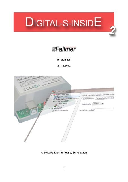
<strong>Version</strong> <strong>2.11</strong><br />
<strong>21.12.<strong>2012</strong></strong><br />
<strong>©</strong> <strong>2012</strong> <strong>Falkner</strong> <strong>Software</strong>, Schwabach<br />
1
Table of Contents<br />
1. Preface - What is Digital-S-Inside? ..................................................................................2<br />
2. Installation........................................................................................................................3<br />
2.1. System Requirements ..............................................................................................3<br />
2.2. Setup ........................................................................................................................3<br />
2.3. DigiCom Installation..................................................................................................6<br />
2.4. DigiCom Uninstallation .............................................................................................8<br />
2.5. Activating the DiCoStation ........................................................................................9<br />
2.6. Demo Mode ..............................................................................................................9<br />
2.7. Uninstallation ..........................................................................................................10<br />
3. The Digital-S-Inside Suite .............................................................................................. 11<br />
3.1. DigiCom..................................................................................................................12<br />
3.2. Digital System.........................................................................................................15<br />
3.2.1. DiCoStation .....................................................................................................16<br />
3.2.1.1. TrainControl..............................................................................................21<br />
3.2.1.2. Keyboard..................................................................................................22<br />
3.2.1.3. LocoProgrammer......................................................................................23<br />
3.2.1.4. Xlight-Finder.............................................................................................24<br />
3.2.2. HSI-88 .............................................................................................................25<br />
3.2.2.1. Feedback Monitor.....................................................................................26<br />
4. Network Capability (for Experts) ....................................................................................26<br />
5. Technical Information .....................................................................................................27<br />
6. Technical Support ..........................................................................................................27<br />
1. Preface - What is Digital-S-Inside?<br />
Thank you very much for your decision to purchase the Digital-S-Inside.<br />
Digital-S-Inside (following called DSI) is a software which revalues your DiCoStation to a<br />
full-functional digital command station for your digital model railway layout.<br />
For using the DSI you need necessarily a DiCoStation.<br />
For the control of locomotives and switching magnetic accessories for an automatic driving<br />
operation is in addition a track image control program e.g. Windigipet required. For a<br />
functional test you can use the enclosed Suite for testing the Locomotive- and Switch-<br />
Decoder.<br />
This manual will describe only the <strong>Software</strong> Digital-S-Inside. The connection of the<br />
DiCoStation respectively HSI-88 USB as well as the related transformer and booster is not<br />
subject of this manual. The respective instruction will be supplied together with the units.<br />
2
2. Installation<br />
DSI can be downloaded from the Internet site www.modellplan.de and tested free of<br />
charge.<br />
For a continual operation you will have to purchase an activation code for each<br />
DiCoStation. You can purchase the activation codes by www.modellplan.de .<br />
Dsi of version 2 can be installed parallel to an existing Dsi version 1.<br />
An existing configuration will not be taken over.<br />
2.1. System Requirements<br />
For DSI is a Windows-PC required. The following Window versions will be supported:<br />
Windows 8, 32 & 64 Bit<br />
Windows 7, 32 & 64 Bit<br />
Windows Vista from Service Pack 2, 32 & 64 Bit<br />
Windows XP from Service Pack 3<br />
A graphic board with a minimum of 16 Bit color depth is recommended.<br />
For connecting the DiCoStation respectively the HSI-88 USB you require an available<br />
USB-Port with a version 1.1. or higher.<br />
2.2. Setup<br />
The supply consists of an installation file “Dsi-2_xx_Setup.exe” which can be downloaded<br />
or found on your CD. „xx“ indicates the actual number of version.<br />
The installation will start after a double click onto the installation file.<br />
Follow the installation assistant.<br />
Under Windows 8, 7 and Vista it is eventually required to allow the installation program a<br />
feedback to the program of your computer.<br />
Select the required language for the Assistant:<br />
The assistant will guide you through the installation:<br />
3
Select the required Installation-Directory:<br />
Select the start Menu-File:<br />
4
The software will now be installed:<br />
The installation is now completed:<br />
You can start DSI via the DSI-2 Symbol on the desktop:<br />
If your control program does not directly support DSI-2 you have to install DigiCom (see<br />
2.3.).<br />
5
2.3. DigiCom Installation<br />
DigiCom is a virtual serial interface for the connection of control programs which do not<br />
support the DSI directly. If your control program supports the DSI-2 directly it is not<br />
required to install the DigiCom.<br />
For the installation please mark at the left window the upper entry “Digital-S-Inside Suite”.<br />
Now click onto the connection symbol with the red plus:<br />
Follow now the advice of the assistant.<br />
6
After successful installation you will find at the left selection-window the entry “DigiCom”<br />
followed by a COM Connection Number e.g.COM3.<br />
You have to configure this Connection Number at your control-program for the connection<br />
to the DSI.<br />
7
2.4. DigiCom Uninstallation<br />
For uninstalling please mark at the left selection window the entry “DigiCom”.<br />
Now click onto the connection symbol with the red minus:<br />
The entry “DigiCom” at the election window will disappear after the uninstallation.<br />
8
2.5. Activating the DiCoStation<br />
DSI will extend your DiCoStation to a full functional digital command station.<br />
Each unit contains a definite serial number (at the picture: dummy no. 0).<br />
For the continue operation you have to purchase for each DiCoStation an activation code<br />
which is available by www.modellplan.de.<br />
Without a valid activation code the operation of the DiCoStation will be running in demomode.<br />
2.6. Demo Mode<br />
Within the demo mode is it possible to test the DSI. The track voltage can be switched-on<br />
for max. 5 Minutes. The time is running after first switching-on of the track voltage. After<br />
this duration the track voltage will be automatically switched-off. For each additional test<br />
you have to start DSI again.<br />
9
2.7. Uninstallation<br />
If you have DigiCom installed please uninstall this program first.<br />
At the start-menu you will find under “All Programs → Digital-S-Inside” the option “Uninstall<br />
Digital-S-Inside”.<br />
With this assistant you can uninstall the DSI:<br />
The uninstallation has been completed:<br />
10
3. The Digital-S-Inside Suite<br />
The Suite is able to configure the DSI and to test the decoders and feedback modules.<br />
The Suite is divided into three window sections. At the left area is a selection window with<br />
a hierarchic structure where the components to be configured can to be selected (e.g.<br />
DigiCom, HSI-88 etc.).<br />
At the right window area you can see the related configuration window.<br />
Some of those configuration windows are separated with several file-flags for getting a<br />
better overview.<br />
The lower window area contains the report window.<br />
This window reports the status- and the failure report of the system.<br />
Reference reports will be indicated in black color, warning indication in blue and error<br />
messages will be red.<br />
3. a) The Digital-S-Inside Suite – Settings<br />
Language: The language of Suite is as standard according to the language selected at<br />
the Windows setting of the PC. Presently will be the German and the English language<br />
supported. You can select here one of the two languages.<br />
Dsi-Service local starting: Here you can adjust if the Dsi-Service of your local PC shall<br />
be started together with Suite. The Dsi-Service should run on the PC which is connected to<br />
the model railway hardware which shall be used via Dsi.<br />
11
Number of elements at the keyboard: Here you can enter the quantity of magnetic<br />
accessories switching buttons to be indicated at one keyboard side of the digital system.<br />
Quantity of elements within the feedback monitor: Here you can enter the quantity of<br />
feedback elements which shall be indicated on one side of the feedback monitor of a<br />
digital system.<br />
3.1. DigiCom<br />
DigiCom is a virtual serial interface for the connection of control programs which do not<br />
support DSI direct. This entry at the selection window will turn up only if DigiCom has been<br />
installed. The port number (COM) indicates the serial interface on which DSI can be<br />
contacted by the control program.<br />
3.1. a) DigiCom – Basic Settings<br />
At the upper rim of the configuration page you can find the actual version of your DigiCom<br />
and the related driver. On the right side you can activate or deactivate DigiCom.<br />
Emulator mode: DigiCom simulates an Intellibox or a Märklin-Interface 6051. Please<br />
enter which command station your control program supports. If both will be supported you<br />
should prefer the Intellibox.<br />
12
Dsi-Host: For the control of the layout DigiCom uses the Dsi-Service of the indicated<br />
computer. As standard will this be the Dsi-Service of the local computer.<br />
3.1. b) DigiCom – Protocol Locodecoder<br />
The protocol of the central unit which is simulating DigiCom does not contain any<br />
information about the protocol (MM/DCC) of the loco-decoder to be contacted. On this<br />
configuration site you can adjust to which decoder-protocol the locomotive shall respond.<br />
You can find detailed information about the protocols at the section: ”Technical<br />
Information”.<br />
Default protocol: Here you can enter which protocol shall be used if no single address or<br />
address range has been indicated or applied.<br />
Addresses: Here you can assign a single loc-address to a particular decoder protocol.<br />
Address ranges: Here you can assign a total range of loc-addresses to a particular<br />
decoder protocol.<br />
At the above screenshot will be the protocol M2 used as a standard. The locomotive with<br />
the address 13 will respond to M2 and the locomotive with address 44 will respond to M5.<br />
All locs of 10 to 19 are using D0 and 20 to 29 are using D2 as decoder protocol.<br />
13
3.1. c) DigiCom – Protocol Switch-Decoder<br />
The protocol of the central unit which is simulating DigiCom does not contain any<br />
information about the protocol (MM/DCC) of the switch-decoder to be contacted. On this<br />
configuration site you can adjust to which decoder-protocol the magnetic accessories shall<br />
respond. You can find detailed information about the protocols at the section: ”Technical<br />
Information”.<br />
Default protocol: Here you can enter which protocol shall be used if no single address or<br />
address range has been indicated or responded.<br />
Addresses: Here you can assign a single magnetic accessory address to a particular<br />
decoder protocol.<br />
Address ranges: Here you can assign a total range of magnetic accessory addresses to<br />
a particular decoder protocol.<br />
At the above screenshot will be the protocol MM used as a standard. The magnetic<br />
accessory with the address 21 will respond to DCC and the magnetic accessory with<br />
address 44 will respond to MM. All magnetic accessories of 40 to 50 are using DCC as<br />
decoder protocol.<br />
14
3.2. Digital System<br />
Under this entry will be all digital systems indicated at a hierarchic order which have been<br />
found by the system. This can be e.g. one or several DiCoStations or HSI-88.<br />
3.2. a) Digital Systems at a Local- or Network-Computer<br />
Dsi-Service: Here will be the version of the Dsi-Service indicated which is connected to<br />
the Suite.<br />
active: Here you can activate or deactivate the connection to the Dsi-Service.<br />
Dsi-Host: Here you can enter with which Dsi-Service on which computer Suite shall be<br />
connected for the control of the digital systems. At standard this will be the Dsi-Service of<br />
the local computer.<br />
15
3.2.1. DiCoStation<br />
Here you can find the configuration of the DiCoStation.<br />
3.2.1. a) DiCoStation - Activation<br />
active: Here you can activate or deactivate the DiCoStation.<br />
Serial number: Each DiCoStation has an individual explicit serial number. This number<br />
will be here indicated.<br />
Activation code: For permanent operation you will have to buy an activation code for<br />
each DiCoStation. This code can be purchased by www.modellplan.de. The activation<br />
code shall be entered here. The DiCoStation will run in demonstration mode without valid<br />
activation code.<br />
16
3.2.1. b) DiCoStation – Basic Settings<br />
Port: Each DiCoStation will create an own ongoing port number by connection to the USB.<br />
This procedure will assure that the correct DiCoStation will be contacted if temporary not<br />
all DiCoStation are connected. If only one DiCoStation is connected this station has the<br />
number USB1.<br />
Short Circuit Detection: Here you can enter the milliseconds between detection of a<br />
short circuit and the switching-off of the track voltage<br />
Repeat Cycle Decrease: The DiCoStation sends permanently repeated decodercommands<br />
of all contacted loc-decoders onto the track. Dsi is able to send the repeated<br />
commands as shortcut for a faster contact to all locomotives. This is eventually not<br />
compatible.<br />
Repeat Cycle Limit: By dynamic shortening will be the repeated cycle automatically<br />
shortened if the entered quantity of loc-decoder has been contacted.<br />
17
3.2.1. c) DiCoStation – MM-Format<br />
Switching direction reversing: Reverse the switching direction of all magnetic<br />
accessories.<br />
Multifunction decoder and direction impulse: Here you can adjust if the DiCoStation<br />
shall send the new Motorola format without drive direction impulse or as well the old format<br />
with drive direction impulse. This mixed operation is as well important for old Multifunction-<br />
Decoder. This complies to the Dip-Switch 1 of the Märklin 6021.<br />
MM-Format: Here you can adjust if the DiCoStation shall send the old Motorola-Format<br />
M1 without drive direction information or the new Format M2 and bigger. This complies to<br />
Dip-Switch 2 of the Märklin 6021.<br />
Data interruption decrease: This is only required for the new Motorola-Format. The<br />
digital packages will be faster transmitted. This is not compatible to the chips of older<br />
decoder (before 701.13, e.g. LME03 – LME=Lenz Märklin Electronics). This complies to<br />
Dip-Switch 3 of the Märklin 6021.<br />
Multifunction-Decoder into repeat-cycle: This is a Dsi-Extension to include switch<br />
information of a Multifunctional-Decoder within the repeat-cycle. This provides several<br />
special functions e.g. the coach illumination will remain switched-on even after the wagon<br />
has lost temporarily contact to the rail. Unfortunately some Switch-Decoder do not accept<br />
the programming. Therefore is this option switched-off as standard setting.<br />
18
3.2.1. d) DiCoStation – DCC-Format<br />
Switch direction reversing: Reversing the switch direction of all magnetic accessories.<br />
3.2.1. e) DiCoStation – Xlight<br />
active: Xlight activation or deactivation. If Xlight has been switched-on all mfx-Decoder are<br />
responding via Xlight only.<br />
19
Xlight-Id of Central: Definite identification of the Xlight-Center. All programmed<br />
locomotive-addresses of the Loc-Decoders are related in connection with the adjusted<br />
Xlight-Id only.<br />
The Xlight-Protocol of Digital-S-Inside supports 126 driving steps and up to 16 switchfunctions<br />
of the mfx-Decoder. The configuration will be not very comfortable because the<br />
DiCoStation offers no feedback report. Therefore we will identify the Xlight-support in<br />
connection with the DiCoStation as “experimental” as there is no assured feature available<br />
from Digital-S-Inside.<br />
To respond a Loc-Decoder with Xlight is the UID of the Loc-Decoder required. The UID is a<br />
world-wide explicit number of any mfx-Decoder. Knowing this UID number enables the<br />
Xlight-Finder (see 3.2.1.4.) to assign a normal loc-address to the decoder. The decoder<br />
will respond to this address as by any other protocols.<br />
There are 4 possibilities to identify the UID of the mfx-Decoder:<br />
a) You can search for the UID with the Xlight-Finder (see 3.2.1.4.). With the first generation<br />
mfx-Decoders from Märklin exists a fair chance to find the UID within a few hours because<br />
the numbers are in descending order of FF:FF:FF:FF. On new decoders the numbers are<br />
scattered at different sections. There is only little change to find the UID within an<br />
acceptable time. A complete scan of all possible numbers could need about 2 years.<br />
b) With the ESU LokProgrammer you can read the UID of all ESU-Decoders and the<br />
Märklin-Decoder of the first generation. It is not possible to read the UID of the Märklin-<br />
Decoder of the new generation.<br />
c) The Tams-Central Unit EasyControl can identify the UID of mxf-Decoder on the<br />
programming track.<br />
d) The Central Station 2 indicates the UID of the recognized Decoder not directly but you<br />
can get the UID with a trick.<br />
At first the CS2 has to recognize the decoder. Then you have to create a data-backup of<br />
the CS2 on a USB-Stick. At the zipped backup copy you can find the file "lokomotive.cs2".<br />
You can open this file with a text-editor. There you can find the UID as "mfxuid".<br />
If you have no possibility to identify the UID you can eventually ask a friend or your<br />
software dealer for help by using a suitable device.<br />
20
3.2.1.1. TrainControl<br />
With TrainControl you can test the function of a Loc-Decoder.<br />
Select the protocol and the address of a Loc-Decoder then click onto “apply”. Now will be a<br />
speed regulator and function keys indicated corresponding to the selected protocol.<br />
With “stop” and “go” is it possible to switch the track voltage on or off.<br />
21
3.2.1.2. Keyboard<br />
With the Keyboard you can test the function of a switch decoder.<br />
For testing please select the protocol and the address section of the switch decoder and<br />
click onto “apply”. Now switch buttons for switching will be indicated.<br />
With “stop” and “go” you can switch-on or off the track voltage.<br />
22
3.2.1.3. LocoProgrammer<br />
With the LocoProgrammer is the programming of the CV-Register of loc-decoder possible.<br />
The programming of the following protocols will be supported:<br />
MM (Märklin Motorola)<br />
DCC PoM (Programming on the Main)<br />
For programming the decoder select at first the track connection which is connected to the<br />
track where the locomotive is located. The DiCoStation contains no programming-track<br />
therefore the main track has to be used. Select now the protocol for the programming.<br />
Now enter the actual address of the decoder and activate the button “Apply“.<br />
Select the number of the CV-Register and the wanted value and activate to button “CV<br />
write”. You can repeat this operation several times.<br />
By activating the button “End programming” you can close the programming process.<br />
The meaning of the CV-Register can be normally found within the instruction of the<br />
decoder.<br />
23
3.2.1.4. Xlight-Finder<br />
With the Xlight-Finder you can search for the UID of a mfx-Decoder and assign a normal<br />
address to the decoder. The Xlight-Finder will be indicated only if Xlight will be<br />
activated at the configuration of the DiCoStation. Particular details and general<br />
information about Xlight can be found at 3.2.1. e).<br />
To assign an address to a locomotive select at first the track connection which is<br />
connected to the track where the loc is located. The DiCoStation contains no<br />
programming-track therefore the main track has to be used. Activate now the button<br />
“Apply”. Enter now the address for the loc. Select the switch-function (F0 – F15) for the<br />
confirmation of the successful programming.<br />
Especially by scanning an UID-section is it advisable to select a switch-function which can<br />
be permanently recognized (e.g. light). Never use a switch-function which can produce a<br />
defect during long time operation (e.g. smoke generator).<br />
Now enter if you do know the UID of the Loc-decoder or if the UID shall be search for.<br />
a) UID-Range scanning:<br />
Enter the range to be scanned and activate the button “Scanning”.<br />
b) UID known:<br />
Enter the UID of the decoder and activate the button “Writing Address”.<br />
Finally you can close the programming process with the button “End programming”.<br />
24
3.2.2. HSI-88<br />
Here you find the configuration of the HSI-88.<br />
Important Note:<br />
Please take care that the HSI-88 should only be activated here if your control program<br />
does not support the HSI-88. If your control program is able to support the HSI-88 this<br />
should be preferred and the HSI-88 shall remain here deactivated.<br />
HSI-88 <strong>Version</strong>: <strong>Version</strong> of the connected HSI-88.<br />
active: Here can be the HSI-88 activated respectively deactivated.<br />
Port Type: Register if the HSI-88 has been serial or USB connected.<br />
Port Number: Number of the COM- or USB-connection.<br />
Feedback Modules on each Bus-Line: Here you have to register how many Feedback-<br />
Decoder are connected to each line of the HSI-88. The total summary should not extend<br />
31.<br />
25
3.2.2.1. Feedback Monitor<br />
You can test the function of a feedback decoder with the Feedback Monitor.<br />
Select the bus and the address range of the feedback decoder and click onto “apply”. The<br />
status of the feedback contacts will be indicated.<br />
4. Network Capability (for Experts)<br />
Dsi consists technically out of three single components which communicate via a TCP/IP-<br />
Network. Within a simple case all three components will run on the local Computer. If you<br />
do know a little about network functions you can have the option e.g. to connect the<br />
hardware to one Computer and the control program onto a separate Computer.<br />
a) The Dsi-Service (“DsiService.exe”) is a server-program which runs in the background<br />
without an own screen display. It controls the connected hardware e.g. a DiCoStation or a<br />
HSI-88 and provides their functions via the network. Therefore is it required that the Dsi-<br />
Service has to run on the computer which has been connected to the hardware.<br />
b) DigiCom (“DigiComService.exe”) is a service for the simulation of an Intellibox via a<br />
virtual serial interface. DigiCom will register as client on a Dsi-Service for the control of<br />
Dsi. It provides the own functionality via a virtual serial interface. The DigiCom-Service has<br />
to run always on the Computer on which the control program e.g. Windigipet shall run.<br />
26
c) The Dsi-Suite (“DsiSuite.exe”) is a graphic surface for configuration and test of Dsi. The<br />
Suite will register as client at a Dsi-Service. Therefore is it possible to configure and test a<br />
Dsi-Service which runs on a separate Computer.<br />
The standard configuration is that starting Suite will start the Dsi-Service and eventually<br />
the DigiCom as well.<br />
5. Technical Information<br />
Digital formats supported by DSI-2 together with the DiCoStation:<br />
Loc-Decoder<br />
Format Sub format Addresses Driving steps Function<br />
Motorola M1 80 14 F0<br />
Motorola M2 80 14 F0-F4*<br />
Motorola M3 255 28 F0-F4*<br />
Motorola M4 255 14 F0-F4*<br />
Motorola M5 80 27 F0-F4*<br />
DCC D0 127 14 F0-F28<br />
DCC D1 127 28 F0-F28<br />
DCC D2 127 126 F0-F28<br />
DCC D3 16127 28 F0-F28<br />
DCC D4 16127 126 F0-F28<br />
Xlight X0 16383 126 F0-F15<br />
*F5-F8 via second address<br />
The quantity of driving steps shall be indicated without driving step 0.<br />
Switch-Decoder<br />
Format Decoder addresses Magnet accessory addresses<br />
Motorola 80 320<br />
DCC 512 2048<br />
6. Technical Support<br />
If you have program related questions please contact directly DIGITAL-S-INSIDE<br />
INFO-LINE:<br />
E-mail-Service: digitals@modellplan.de<br />
Telephone-Service: 0049 160 96 32 84 62<br />
(Mondays from 7pm to 9pm)<br />
27<br />
Subject to technical changes and errors.