Laue indexing manual.pdf
Laue indexing manual.pdf
Laue indexing manual.pdf

You also want an ePaper? Increase the reach of your titles
YUMPU automatically turns print PDFs into web optimized ePapers that Google loves.
Introduction<br />
This program is designed for <strong>indexing</strong> <strong>Laue</strong> patterns, finding of the<br />
orientation of monocrystal. Unlike the other software, which solve this task by<br />
calculation the angles between the planes, this program uses the classical principle<br />
of Stereographic projection calculation, finding the points of projection, which<br />
align with arcs (meredians), analytical rotation of crystal to coincide the<br />
Stereographic projection with Standard projection.<br />
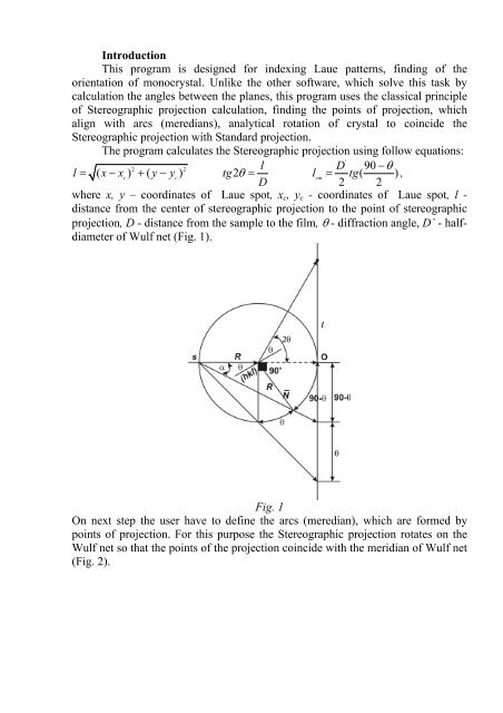
The program calculates the Stereographic projection using follow equations:<br />
'<br />
2 2<br />
l<br />
D 90 <br />
l ( xx ) ( y y ) tg2<br />
l tg(<br />
) ,<br />
c c<br />
D<br />
ст<br />
2 2<br />
where x, y – coordinates of <strong>Laue</strong> spot, xc, yc - coordinates of <strong>Laue</strong> spot, l -<br />
distance from the center of stereographic projection to the point of stereographic<br />
projection, D - distance from the sample to the film, - diffraction angle, D` - halfdiameter<br />
of Wulf net (Fig. 1).<br />
Fig. 1<br />
On next step the user have to define the arcs (meredian), which are formed by<br />
points of projection. For this purpose the Stereographic projection rotates on the<br />
Wulf net so that the points of the projection coincide with the meridian of Wulf net<br />
(Fig. 2).
Fig. 2<br />
The rotation of the projection is defined by the equations:
x x<br />
y y<br />
i c<br />
i c<br />
x x i c<br />
y y<br />
i c<br />
yy arctg<br />
xx c<br />
c<br />
' 180 <br />
<br />
x x2sin l cos <br />
2 2 <br />
' 180 <br />
<br />
y y2sin l sin <br />
2 2 <br />
' y y ст c<br />
arctg<br />
x x ст c<br />
' 180 <br />
'<br />
x x 2l sin cos<br />
ст ст ст <br />
2 2 <br />
' 180 <br />
'<br />
y y 2l sin sin <br />
ст ст ст <br />
2 2 <br />
yy arctg<br />
xx '<br />
x x l<br />
'<br />
y y l<br />
'<br />
<br />
c<br />
c<br />
<br />
2sin sin <br />
2 2<br />
<br />
2sin cos <br />
2 2<br />
y y ст c<br />
arctg<br />
x x<br />
ст c<br />
' ' <br />
x x 2l sin sin<br />
ст ст ст <br />
2 2<br />
' ' <br />
y y 2l sin cos <br />
ст ст ст <br />
2 2
x x<br />
y y<br />
i c<br />
i c<br />
x x i c<br />
y y<br />
i c<br />
x x i c<br />
y y<br />
i c<br />
' 180 <br />
<br />
x x2sin l sin <br />
2 2 <br />
' 180 <br />
<br />
y y2sin l cos <br />
2 2 <br />
'<br />
180 <br />
<br />
x x 2l sin sin<br />
ст ст ст <br />
2 2 <br />
'<br />
180 <br />
<br />
y y 2l sin cos<br />
ст ст ст <br />
2 2 <br />
' 180 <br />
<br />
x x2sin l sin <br />
2 2 <br />
' 180 <br />
<br />
y y2sin l cos <br />
2 2 <br />
'<br />
180 <br />
<br />
x x 2l sin sin<br />
ст ст ст <br />
2 2 <br />
'<br />
180 <br />
<br />
y y 2l sin cos<br />
ст ст ст <br />
2 2 <br />
' 180 <br />
<br />
x x2sin l cos <br />
2 2 <br />
' 180 <br />
<br />
y y2sin l sin <br />
2 2 <br />
'<br />
180 <br />
<br />
x x 2l sin cos<br />
ст ст ст <br />
2 2 <br />
'<br />
180 <br />
<br />
y y 2l sin sin<br />
ст ст ст <br />
2 2
' 180 <br />
<br />
x x2sin l cos <br />
2 2 <br />
' 180 <br />
<br />
y y2sin l sin<br />
x x<br />
<br />
i c<br />
2 2 <br />
,<br />
y y i c '<br />
180 <br />
<br />
x x 2l sin cos<br />
ст ст ст <br />
2 2 <br />
'<br />
180 <br />
<br />
y y 2l sin sin<br />
ст ст ст <br />
2 2 <br />
where - angle of rotation. The Wulf net coordinates are define by:<br />
cossin x2R 1cos cos <br />
<br />
<br />
sin<br />
y2R 1cos cos<br />
where - longitude, - latitude, R- radius of Wulf net.<br />
The program also calculates the pole of the pole of planes, which is distant<br />
from the meridian by 90 o (Fig. 2). The user has to define 4 meridians (Fig. 3).<br />
Fig. 3<br />
One should pay attention to the points of the projection, which lies on the intercept<br />
of two meridians (Fig. 3). They are very important because corresponds the planes<br />
with small Miller indices such as (001), (110), (111). To find the orientation of<br />
crystal it is necessary to transform the stereographic projection of the crystal into<br />
the Standard projection. It can be done by rotation of the stereographic projection<br />
,
elative to the Wulf Net and analytical rotation the crystal and the projection by<br />
angle . The points of projection move in parallels by rotation of crystal (Fig. 4).<br />
Fig. 4<br />
For coincidence of the stereographic projection of the crystal with standard<br />
projection it is necessary to choose appropriate Standard projection. The<br />
coordinates of standard projection are defined by:<br />
nhkl<br />
h2 2 2<br />
<br />
1cos cos cos 2coscos<br />
cos<br />
<br />
<br />
a<br />
<br />
k h<br />
<br />
<br />
<br />
<br />
<br />
<br />
b a<br />
<br />
<br />
h k cos cos cos hcos<br />
<br />
( cos ) ( c sin )<br />
<br />
<br />
a b sin<br />
a<br />
<br />
<br />
2 2 2<br />
( ) ( cos ) 1 cos cos cos 2cos cos cos<br />
where n – normal vector in orthogonal system coordinate, a, b, c, , , - lattice<br />
parameters, h, k, l- Miller indices of plane.<br />
,
ZaZ , , a Z<br />
X arccos( nhkl ( ), Z)<br />
S0 Z, n( hkl) Z<br />
cZZ , , a Z<br />
,<br />
<br />
where Z - pole of standard projection, a, c – direction perpendicular to Z, - angle<br />
between vector of reference direction Z and normal to the plane n(hkl).<br />
, Z Z, n( hkl)<br />
<br />
<br />
0<br />
x<br />
cos<br />
arccos( S0, X)<br />
<br />
r Rtg<br />
,<br />
360 , Z Z, n( hkl)<br />
<br />
<br />
0<br />
y<br />
sin<br />
where R- radius Wulf net, -polar angle.<br />
The best solution for the orientation of monocrystal correspond the situation when<br />
the most important points of the projection (points of meridians intercept and<br />
poles) coincide with Standard projection (Fig. 5).<br />
Fig. 5
<strong>Laue</strong> <strong>indexing</strong> <strong>manual</strong><br />
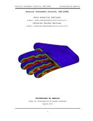
1. Required software: ImageJ, Matcad 2001 or later. Before to start it is necessary<br />
to scan X-ray photograph with resolution at least 300dpi.<br />
2. Open ImageJ. Find a file with <strong>Laue</strong> Photograph File->Open (Fig. 1).<br />
Fig. 1<br />
3. Set a scale for the <strong>Laue</strong>gramm: Analyze->Set Scale (Fig. 2). Fill in the fild<br />
Distance in Pixels the resolution of the Fhoto (300 dpi), in the field “Known<br />
Distance” set the distance between two points on the <strong>Laue</strong> pattern in mm (in<br />
our example 25.4 mm, because 1inch is equals 25.4 mm), in the field “Unit of<br />
Length” set the used unit dimension (mm).<br />
4. Press key Point Selection (Fig. 3) and holding pressed key Shift define the <strong>Laue</strong><br />
spots on the Photograph by clicking on them left key of Mouse (Fig. 4).
Fig. 2<br />
Fig. 3
Fig. 4<br />
5. After that choose the menu “Analyze->Measure”. It will appear the table with<br />
results (Results) (Fig. 4). Save the results “File->Save as” by name <strong>Laue</strong><br />
Spots.dat (We actually need only two columns X,Y. For this purpose the data<br />
could be exported in software Origin lab or others. After that we can export file<br />
again with the same name). Now we have to define the center of <strong>Laue</strong> pattern,<br />
that is the point in which the incident white X-ray beam intercepts the X-ray<br />
Film. Press key “Elliptical or brash selection” (Fig. 5).<br />
6. Holding left mouse key pressed draw the ellipse on the <strong>Laue</strong> pattern so that, it<br />
fill the dark spot in the place of X-ray beam intercept (Fig. 6).<br />
7. In order to calculate the coordinates of the center we need to use menu “Image-<br />
>Show Info” (Fig. 7). The coordinates of X-ray pattern defined by following:<br />
x=X+Width/2; x=Y+Height/2, (46.48+10.16/2=51.56; 41.40+10.16/2=46.48).<br />
The obtained results should be saved.<br />
8. Open MathCad and find the file <strong>Laue</strong> <strong>indexing</strong>.mcd.
9. Open file with <strong>Laue</strong> spots coordinates (right mouse click -> Choose file) (Fig.<br />
8).<br />
Fig. 5<br />
Fig. 6
Fig. 7<br />
Fig. 8
10. Define coordinates of the center of <strong>Laue</strong> Pattern: xc=51.56; yc=46.48<br />
11. Now we have to make the coincidence of our <strong>Laue</strong> pattern with one of the<br />
Meredian of Wulf net (Fig. 10). This could be done by rotation of<br />
<strong>Laue</strong>gramm by angle (Fig. 9).<br />
Fig. 9<br />
We have to realize that the rotation by angle >0 rotates the stereographic<br />
projection anti-clockwise, and the rotation by angle
12. Define angle 2=-6 о , which corresponds the rotation of the projection<br />
Fig. 10<br />
Fig. 11
in the opposite side to the rotation by angle (Fig. 12,13). By this the meridian<br />
formed by stereographic projections of pole of planes will become the initial<br />
position (before rotation).<br />
Fig. 12<br />
Fig. 13
13. Next step is to make the coincidence of our <strong>Laue</strong> pattern with the second of<br />
the Meredian of Wulf net. This requires the rotation of <strong>Laue</strong>gramm by angle<br />
=-5 (Fig. 14).<br />
The results can be seen on Fig. 15.<br />
Fig. 14<br />
Fig. 15
To draw the second meridian we have to define angle 3=70 о , which is<br />
distant from the Great Circle on the left side from the center of Wulf net by<br />
angle 20 о . Right picture shows for comparison the initial projection before<br />
rotation.<br />
14. Define the angle 4=5 о , which corresponds the rotation of meridian in<br />
opposite side to the rotation by angle (Fig. 16). By this procedure the<br />
meridian will come to the initial position.<br />
Fig. 16<br />
To find the third meridian on the <strong>Laue</strong> Pattern the stereographic projection<br />
of sample should be rotate by angle =86 о . Fig. 17 shows the result of this<br />
rotation. To draw the meridian define the angle 5=68 о . This meridian is<br />
distant from the Great Circle of Wulf net on the left side from the center of<br />
Wulf net by angle 22 о . Right picture shows for comparison the initial<br />
projection before rotation.<br />
15. Define angle 6=-86 о , which corresponds the rotation of meridian in<br />
opposite side to the rotation by angle (Fig. 18). By this procedure the<br />
meridian will come to the initial position.
Fig. 17<br />
Fig. 18<br />
16. To combine the forth meridian of Wulf net with our stereographic<br />
projection, the later is rotated by angle =92 о . The result of rotation can be<br />
seen on Fig. 19.
Fig. 19<br />
17. To draw the meridian one defines the angle 7=-64 о , which is distant from<br />
the Great Circle of Wulf net on the left side from the center of Wulf net by<br />
angle 26 о . On the right picture is shown the initial projection before rotation.<br />
18. We also have to define angle 8=-92 о , corresponded the rotation of meridian<br />
in opposite side relative to the rotation by angle (Fig. 20). By this<br />
procedure the meridian will come to the initial position. Therefore we have<br />
found 4 meridians, corresponded 4 poles of planes in our sample (Fig.20).<br />
This quantity of poles is quite enough to determine the orientation of crystal.<br />
19. If it is necessary, we can save the results at file meredians.dat (Fig. 21) and<br />
coordinates of points of Wulf net Wulfnet.dat (Fig. 22) for next calculations.<br />
20. On the next step we have to think about which meridian will be used for<br />
analytical rotation of crystal. The best way to choose the meridian, which<br />
contains maximal quantity of stereographic projections and rotate the crystal<br />
analytically кристалл by angle . In this example we define meridian,<br />
which corresponds rotation angle =6 о (2=-6 о ) in relation to horizontal axis<br />
or equator of Wulf net (Fig. 10). To do this define angle (Fig. 23). This
meridian is distant from the Great Circle of Wulf net (on the left side) by<br />
angle =24 о .<br />
21. Then rotate crystal by angle =-24 о (Fig. 24). As a result all point of the<br />
projection (red) must to shift by parallels on the left side (blue) by this angle<br />
(Fig. 25).<br />
Fig. 20<br />
Fig. 21
Fig. 22<br />
Fig. 23<br />
22. Define the lattice parameters of our crystal (a1, b1, c1, , , γ) and pole of<br />
standard projection (Fig. 26). In our example we draw the standard projection<br />
(111) (Fig. 27).
Fig. 24<br />
Fig. 25
Fig. 26<br />
Fig. 27
23. We have two ways to find the appropriate coincidence of the stereographic<br />
projection of the sample (blue) with the points chosen Standard projection<br />
(black):<br />
to rotate the stereographic projection of the sample relative to the standard<br />
projection. The rotation angle is designed as 1 (Fig. 28).<br />
to rotate the standard projection relative to the stereographic projection of<br />
the sample. The rotation angle is designed as (Fig. 29).<br />
Fig. 28<br />
Fig. 29
Fig. 30<br />
24. The results of rotation we can see on Fig. 30. You can see the Stereographic<br />
projection before (red circles), and after (blue circles) crystal rotation by angle ,<br />
poles of planes before (red rhombs), and after (blue rhombs), axes X (cyan) and<br />
Y (brown) before crystal rotation and the result of their movement after the<br />
crystal rotation (black circle). Actually, the best result is when the all points of<br />
the stereographic projections (blue) coincide with all points of standard.<br />
However, this happens very seldom due to experimental errors. The most<br />
important points of standard projections are the points in which intercept several<br />
meridians. They correspond planes in crystal with low Miller indices (hkl) such<br />
as (001), (111), (110). Realizing that, we need to find these points on the<br />
stereographic projection of the sample. Next picture illustrates this principle (Fig.<br />
31). You can see the points of stereographic projection of the sample which<br />
forms meridians (pink).
Fig. 31<br />
25. The Miller indices (hkl) of points of Standard projection with their<br />
coordinates X,Y on Wulf net reported in table A2 (Fig. 32). In order to find the<br />
Miller indices of points of Standard projections it is necessary to click right<br />
mouse key by black point on the graph and select menu “Traces”, then choose the<br />
option “Track data points”, then again click left mouse key on the point you want<br />
to determine Miller indices (Fig. 32). In the small window appear the X,Y<br />
coordinates of these point. To find Miller indices of this point you only need to<br />
find the row in table A2, which has the same coordinates (column 3 corresponds<br />
coordinates X, and column 4 corresponds Y). The columns 0,1,2 correspond the<br />
Miller indices of the point on the Standard Projection.
Fig. 32<br />
26. The obtained results you can save in file “crystal rotation and projection.dat”<br />
(Fig. 33) where the columns designate follow:<br />
S0- х coordinates of Stereographic projection of the sample before the crystal<br />
rotation and after the coinsidence of the projection of crystal with standard<br />
projection<br />
S1- y coordinates of Stereographic projection of the sample before the crystal<br />
rotation and after the coinsidence of the projection of crystal with standard<br />
projection<br />
S2- х coordinates of Stereographic projection of the sample after the crystal<br />
rotation and after the coinsidence of the projection of crystal with standard<br />
projection<br />
S3- y coordinates of Stereographic projection of the sample after the crystal<br />
rotation and after the coinsidence of the projection of crystal with standard<br />
projection<br />
S4- х coordinates of the center of projection<br />
S5- y coordinates of the center of projection<br />
S6- х coordinates of Axis X after rotation of crystal after the coinsidence of the<br />
projection of crystal with standard projection<br />
S7- y coordinates of Axis X after rotation of crystal after the coinsidence of the<br />
projection of crystal with standard projection
S8- х coordinates of Axis Y projection after rotation of crystal after the coinsidence<br />
of the projection of crystal with standard projection<br />
S9- y coordinates of Axis Y projection after rotation of crystal after the coinsidence<br />
of the projection of crystal with standard projection<br />
S10- х coordinates of pole of Axis X projection after rotation of crystal and after the<br />
coinsidence of the projection of crystal with standard projection<br />
S11- y coordinates of pole of Axis X projection after rotation of crystal and after the<br />
coinsidence of the projection of crystal with standard projection<br />
S12- х coordinates of pole of Axis Y projection after rotation of crystal and after the<br />
coinsidence of the projection of crystal with standard projection<br />
S13- y coordinates of pole of Axis Y projection after rotation of crystal and after the<br />
coinsidence of the projection of crystal with standard projection<br />
S14- х coordinates of pole of stereographic projections, which form meredian after<br />
rotation of crystal and after the coinsidence of the projection of crystal with<br />
standard projection<br />
S15- y coordinates of pole of stereographic projections, which form meredian after<br />
rotation of crystal and after the coinsidence of the projection of crystal with<br />
standard projection<br />
S16-х coordinates of meredians after rotation of crystal and after the coinsidence of<br />
the projection of crystal with standard projection<br />
S17- y coordinates of meredians after rotation of crystal and after the coinsidence of<br />
the projection of crystal with standard projection<br />
Fig. 33