DWSIM - Process Simulation, Modeling and Optimization User Guide
DWSIM - Process Simulation, Modeling and Optimization User Guide
DWSIM - Process Simulation, Modeling and Optimization User Guide

Create successful ePaper yourself
Turn your PDF publications into a flip-book with our unique Google optimized e-Paper software.
<strong>DWSIM</strong> - <strong>Process</strong> <strong>Simulation</strong>, <strong>Modeling</strong> <strong>and</strong> <strong>Optimization</strong><br />
<strong>User</strong> <strong>Guide</strong><br />
Version 1.7, Revision 0<br />
July 2010
License<br />
<strong>DWSIM</strong> is released under the GNU General Public License (GPL) version 3.<br />
Contact Information<br />
<strong>DWSIM</strong> - <strong>Process</strong> <strong>Simulation</strong>, <strong>Modeling</strong> <strong>and</strong> <strong>Optimization</strong><br />
Author/Developer: Daniel Wagner Oliveira de Medeiros<br />
Website: / <br />
<br />
E-mail:
Contents<br />
1 Introduction 3<br />
2 Welcome screen 4<br />
3 <strong>Simulation</strong> 6<br />
3.1 <strong>User</strong> Interface . . . . . . . . . . . . . . . . . . . . . . . . . . . . . . . . . . . . 6<br />
3.2 Configuration . . . . . . . . . . . . . . . . . . . . . . . . . . . . . . . . . . . . 6<br />
3.2.1 Components . . . . . . . . . . . . . . . . . . . . . . . . . . . . . . . . . 7<br />
3.2.2 Property Package . . . . . . . . . . . . . . . . . . . . . . . . . . . . . . 7<br />
3.2.3 Units systems <strong>and</strong> Number formatting . . . . . . . . . . . . . . . . . . . 10<br />
3.2.4 Other options . . . . . . . . . . . . . . . . . . . . . . . . . . . . . . . . 11<br />
3.3 <strong>Process</strong> modeling (Flowsheeting) . . . . . . . . . . . . . . . . . . . . . . . . . . 12<br />
3.3.1 Objects . . . . . . . . . . . . . . . . . . . . . . . . . . . . . . . . . . . 13<br />
3.3.2 <strong>Process</strong> data management . . . . . . . . . . . . . . . . . . . . . . . . . 18<br />
3.3.3 <strong>Simulation</strong> . . . . . . . . . . . . . . . . . . . . . . . . . . . . . . . . . . 20<br />
3.3.4 Results . . . . . . . . . . . . . . . . . . . . . . . . . . . . . . . . . . . . 21<br />
3.4 Sensitivity Analysis . . . . . . . . . . . . . . . . . . . . . . . . . . . . . . . . . 23<br />
3.5 Flowsheet <strong>Optimization</strong> . . . . . . . . . . . . . . . . . . . . . . . . . . . . . . . 25<br />
3.6 Utilities . . . . . . . . . . . . . . . . . . . . . . . . . . . . . . . . . . . . . . . . 28<br />
3.7 Chemical Reactions . . . . . . . . . . . . . . . . . . . . . . . . . . . . . . . . . 33<br />
3.8 Hypothetical Components <strong>and</strong> Characterization of Petroleum Fractions . . . . . 35<br />
3.8.1 Hypotheticals . . . . . . . . . . . . . . . . . . . . . . . . . . . . . . . . 35<br />
3.8.2 Petroleum Fractions . . . . . . . . . . . . . . . . . . . . . . . . . . . . . 38<br />
3.9 Component Databases . . . . . . . . . . . . . . . . . . . . . . . . . . . . . . . . 40<br />
3.9.1 Databases . . . . . . . . . . . . . . . . . . . . . . . . . . . . . . . . . . 40<br />
3.9.2 Managing Components . . . . . . . . . . . . . . . . . . . . . . . . . . . 41
List of Figures<br />
1 <strong>DWSIM</strong>’s welcome screen. . . . . . . . . . . . . . . . . . . . . . . . . . . . . . 4<br />
2 <strong>DWSIM</strong>’s main window. . . . . . . . . . . . . . . . . . . . . . . . . . . . . . . . 5<br />
3 <strong>Simulation</strong> configuration window. . . . . . . . . . . . . . . . . . . . . . . . . . . 6<br />
4 Property Package configuration interface. . . . . . . . . . . . . . . . . . . . . . 7<br />
5 Property package configuration window (1). . . . . . . . . . . . . . . . . . . . . 8<br />
6 Property package configuration window for EOS-based models. . . . . . . . . . . 9<br />
7 Units system configuration interface. . . . . . . . . . . . . . . . . . . . . . . . . 10<br />
8 Number formatting selection interface. . . . . . . . . . . . . . . . . . . . . . . . 11<br />
9 <strong>Simulation</strong> description editing interface. . . . . . . . . . . . . . . . . . . . . . . 11<br />
10 <strong>Simulation</strong> interface. . . . . . . . . . . . . . . . . . . . . . . . . . . . . . . . . . 12<br />
11 Window repositioning. . . . . . . . . . . . . . . . . . . . . . . . . . . . . . . . . 13<br />
12 Object buttons bar. . . . . . . . . . . . . . . . . . . . . . . . . . . . . . . . . . 15<br />
13 Dragging items from the Object palette window. . . . . . . . . . . . . . . . . . . 16<br />
14 Viewing keyboard shortcuts to add objects. . . . . . . . . . . . . . . . . . . . . 16<br />
15 A material stream in the flowsheet. . . . . . . . . . . . . . . . . . . . . . . . . . 17<br />
16 Selected object context menu. . . . . . . . . . . . . . . . . . . . . . . . . . . . 17<br />
17 Stream selection menu. . . . . . . . . . . . . . . . . . . . . . . . . . . . . . . . 18<br />
18 Compressor with all connections made. . . . . . . . . . . . . . . . . . . . . . . . 18<br />
19 Viewing object properties in the "Selected Object" window. . . . . . . . . . . . . 19<br />
20 Direct editing of a property. . . . . . . . . . . . . . . . . . . . . . . . . . . . . . 19<br />
21 Using an auxiliary window to edit a property value. . . . . . . . . . . . . . . . . 19<br />
22 Selecting a value for the property in a drop-down menu. . . . . . . . . . . . . . 19<br />
23 Calculated objects. . . . . . . . . . . . . . . . . . . . . . . . . . . . . . . . . . 20<br />
24 <strong>DWSIM</strong>’s calculator control bar. . . . . . . . . . . . . . . . . . . . . . . . . . . 21<br />
25 A <strong>DWSIM</strong>’s calculator message. . . . . . . . . . . . . . . . . . . . . . . . . . . 21<br />
26 Results report configuration. . . . . . . . . . . . . . . . . . . . . . . . . . . . . 22<br />
27 Results report. . . . . . . . . . . . . . . . . . . . . . . . . . . . . . . . . . . . . 22<br />
28 Sensitivity Analysis Utility (1). . . . . . . . . . . . . . . . . . . . . . . . . . . . 23<br />
29 Sensitivity Analysis Utility (2). . . . . . . . . . . . . . . . . . . . . . . . . . . . 24<br />
30 Sensitivity Analysis Utility (3). . . . . . . . . . . . . . . . . . . . . . . . . . . . 25<br />
31 Multivariate <strong>Optimization</strong> Utility (1). . . . . . . . . . . . . . . . . . . . . . . . . 26<br />
32 Multivariate <strong>Optimization</strong> Utility (2). . . . . . . . . . . . . . . . . . . . . . . . . 27<br />
33 Multivariate <strong>Optimization</strong> Utility (3). . . . . . . . . . . . . . . . . . . . . . . . . 27<br />
34 Utilities - True Critical Point. . . . . . . . . . . . . . . . . . . . . . . . . . . . . 28<br />
35 Utilities - Hydrate Calculations. . . . . . . . . . . . . . . . . . . . . . . . . . . . 29<br />
36 Utilities - Pure Component Properties. . . . . . . . . . . . . . . . . . . . . . . . 30<br />
37 Utilities - Phase Envelope. . . . . . . . . . . . . . . . . . . . . . . . . . . . . . 31<br />
38 Utilities - Binary Envelope. . . . . . . . . . . . . . . . . . . . . . . . . . . . . . 32<br />
39 Utilities - Petroleum Cold Flow Properties. . . . . . . . . . . . . . . . . . . . . . 33<br />
40 Chemical Reactions Manager. . . . . . . . . . . . . . . . . . . . . . . . . . . . . 34<br />
41 Reaction Set editor. . . . . . . . . . . . . . . . . . . . . . . . . . . . . . . . . . 34<br />
42 Reaction set in a reactor’s property window. . . . . . . . . . . . . . . . . . . . . 35<br />
43 Hypotheticals Generator. . . . . . . . . . . . . . . . . . . . . . . . . . . . . . . 36
List of Figures List of Figures<br />
44 Hypo properties. . . . . . . . . . . . . . . . . . . . . . . . . . . . . . . . . . . . 36<br />
45 Entering data for regression of the parameters for vapor pressure calculation. . . 37<br />
46 Hypo data verification. . . . . . . . . . . . . . . . . . . . . . . . . . . . . . . . 38<br />
47 C7+ petroleum fraction characterization utility. . . . . . . . . . . . . . . . . . . 39<br />
48 Characterizing petroleum from distillation curves. . . . . . . . . . . . . . . . . . 40<br />
49 Database manager. . . . . . . . . . . . . . . . . . . . . . . . . . . . . . . . . . 41<br />
50 Selecting components from the list. . . . . . . . . . . . . . . . . . . . . . . . . . 42<br />
51 Utility for adding user components. . . . . . . . . . . . . . . . . . . . . . . . . . 43<br />
<strong>DWSIM</strong> - <strong>User</strong> <strong>Guide</strong> 2
1 Introduction<br />
1 INTRODUCTION<br />
This <strong>User</strong> <strong>Guide</strong> was created with the purpose to provide information for <strong>DWSIM</strong> users about<br />
the utilization of the software with respect to the GUI, comm<strong>and</strong>s <strong>and</strong> functions available. The<br />
structure of the document is organized according to the sequence of execution of a simple<br />
simulation. Each step is explained with the help of images of the associated windows <strong>and</strong><br />
descriptions for the functions <strong>and</strong> necessary comm<strong>and</strong>s.<br />
For details about the models used for calculation of thermodynamic properties, please view<br />
the Technical Manual. Detailed description about the Unit Operations <strong>and</strong> Utilities can be<br />
found in the Unit Operations <strong>and</strong> Utilities <strong>Guide</strong>.<br />
<strong>DWSIM</strong> - <strong>User</strong> <strong>Guide</strong> 3
2 Welcome screen<br />
2 WELCOME SCREEN<br />
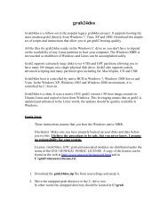
When <strong>DWSIM</strong> is run for the first time, after the database is loaded, the following window<br />
appears (Figure 1):<br />
Figure 1: <strong>DWSIM</strong>’s welcome screen.<br />
The welcome screen provides the user with shortcuts to open existing simulations, create new<br />
ones <strong>and</strong> view the documentation. It is possible to view some usage tips in the bottom of the<br />
window. For this window do not open when <strong>DWSIM</strong> starts, the checkbox "Always show this<br />
window" must be unchecked. The "Close" button close this window <strong>and</strong> shows the main <strong>DWSIM</strong><br />
interface:<br />
<strong>DWSIM</strong> - <strong>User</strong> <strong>Guide</strong> 4
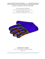
Figure 2: <strong>DWSIM</strong>’s main window.<br />
2 WELCOME SCREEN<br />
In the main <strong>DWSIM</strong> window (Figure 2), it’s possible to view the following items:<br />
➙ Menu bar, with buttons to open/save/create simulations, configure the active simulation,<br />
general preferences, launch tools, configure the child windows view mode, etc.;<br />
If there is an active simulation in <strong>DWSIM</strong>, the menu bar is filled with other specific items.<br />
➙ Button strip, to open, save <strong>and</strong> create new steady-state simulations.<br />
There are various options to access the most commonly operations with simulation files - open,<br />
save <strong>and</strong> create. In the next sections you will be guided through some necessary steps to create<br />
<strong>and</strong> configure a steady-state simulation.<br />
<strong>DWSIM</strong> - <strong>User</strong> <strong>Guide</strong> 5
3 <strong>Simulation</strong><br />
3.1 <strong>User</strong> Interface<br />
3 SIMULATION<br />
The "Create a new steady-state simulation" button in the welcome window can be used to<br />
create a new simulation. After the simulation is created, the configuration window (Figure 3)<br />
is shown. The simulation configuration interface consists in a lateral menu composed by tabs<br />
which, by themselves, are divided in sections:<br />
➙ Components - Contains sections for manage the components in the simulation.<br />
➙ Thermodynamic <strong>and</strong> Reactions - Property Package configuration <strong>and</strong> Chemical Reac-<br />
tions management.<br />
➙ Tools - Creation <strong>and</strong> management of user-created components.<br />
➙ Options - Unit systems management <strong>and</strong> number formatting.<br />
➙ Description - <strong>Simulation</strong> info (title, author <strong>and</strong> description).<br />
3.2 Configuration<br />
Figure 3: <strong>Simulation</strong> configuration window.<br />
The simulation configuration window (Figure 3) is the interface where all the functions for<br />
configuration <strong>and</strong> personalization of a simulation in <strong>DWSIM</strong> are concentrated. In this window,<br />
the user can be manage the simulation components, the property package (thermodynamic<br />
package), units system <strong>and</strong> number format, among other options.<br />
The configuration window can be accessed at any time during the simulation, <strong>and</strong> the<br />
changes made on it have immediate effect. <strong>DWSIM</strong> shows a confirmation box when the user<br />
makes any change to important settings, like the property package selection.<br />
<strong>DWSIM</strong> - <strong>User</strong> <strong>Guide</strong> 6
3.2 Configuration 3 SIMULATION<br />
3.2.1 Components<br />
There are two essential information required by <strong>DWSIM</strong> in order to correctly start a simu-<br />
lation. The first refers to the available components. Operations with the components in a<br />
simulation can be done in the submenus in the "Components" tab. There are three types of<br />
components which can be managed in <strong>DWSIM</strong> - the first type are the components present in<br />
the database. The second, hypotheticals, <strong>and</strong> the third, pseudocomponents, are components<br />
which can be added by the user through the Hypothetical Creation Utility or the Petroleum<br />
Characterization Utilities. These user-created components will be available in the end of the<br />
component list inside the "Components" tab for inclusion or exclusion from the simulation as<br />
necessary.<br />
View the section 3.8 for information about the hypothetical <strong>and</strong> pseudocomponent<br />
generation utilities.<br />
3.2.2 Property Package<br />
The Property Package consists in a set of methods <strong>and</strong> models for the calculation of physical<br />
<strong>and</strong> chemical properties of material streams in the simulation. It is composed of a thermodynamic<br />
model - an equation of state or a hybrid model - <strong>and</strong> methods for property calculation, like the<br />
surface tension of the liquid phase. It is shown in Figure 4 the interface for configuration of the<br />
property package ("Thermodynamic <strong>and</strong> Reactions" tab, "Property Package" section).<br />
Figure 4: Property Package configuration interface.<br />
Extra configuration options for EOS-based Property Packages You can define some op-<br />
tions which will be used throughout all Property Packages, in all simulation objects. They<br />
are:<br />
➙ Flash Algorithm<br />
Select the flash algorithm to be used by <strong>DWSIM</strong>. You can choose between ”Nested Loops”<br />
(default) <strong>and</strong> ”Inside-Out”. The latter is faster in most cases, specially if your simulation contains<br />
<strong>DWSIM</strong> - <strong>User</strong> <strong>Guide</strong> 7
3.2 Configuration 3 SIMULATION<br />
many components. The first is more stable <strong>and</strong> should work on most cases, as it is being used<br />
since early <strong>DWSIM</strong> builds.<br />
➙ Force Pressure-Enthalpy (PH) Flash calculations<br />
If you check the box, all requests by unit operations for PT Flashes will be replaced by PH ones.<br />
This option must be activated if you are working with only one component (steam simulation,<br />
for example), otherwise you won’t have partial vaporization/liquefaction in valves, compressors<br />
<strong>and</strong> exp<strong>and</strong>ers, if that is the case.<br />
➙ Calculate Bubble <strong>and</strong> Dew points at stream conditions<br />
Check this box if you want the <strong>DWSIM</strong> to calculate bubble <strong>and</strong> dew points at conditions<br />
specified on each material stream. The calculated values will be shown only if the stream is at<br />
VLE equilibrium. The calculations are not exactly fast, so use this option with caution <strong>and</strong> only<br />
if needed.<br />
Multiple Property Packages Starting from <strong>DWSIM</strong> 1.5, the user can define more than one<br />
property package to be used in the simulation, which can be associated to each unit operation<br />
on a individual basis. Each property package has its own settings, independently of having two<br />
or more packages of the same type.<br />
Property Package configuration If the selected property package has any editable property,<br />
the "Configure" button becomes activated <strong>and</strong> the user can click on it to show the property<br />
package configuration window. In the case of the SRK property package, the editable parameters<br />
are the binary interaction parameters (Figure 5) <strong>and</strong> some convergence/tolerance values for flash<br />
calculations (Figure 6).<br />
Figure 5: Property package configuration window (1).<br />
<strong>DWSIM</strong> - <strong>User</strong> <strong>Guide</strong> 8
3.2 Configuration 3 SIMULATION<br />
➙ Use Ideal Mixing Rule for Liquid Phase Density<br />
If the liquid phase has small amounts of supercritical components, the default calculation<br />
method may fail. If that is the case, change this option to 1 to force an ideal mixing rule for the<br />
liquid density (use a molar weighted average of individual component liquid densities).<br />
➙ Flash Algorithm<br />
Use this option to override the global setting for the Flash Algorithm. Default is 2 (use the<br />
global setting).<br />
Figure 6: Property package configuration window for EOS-based models.<br />
Extra configuration options for EOS-based Property Packages Some Property Packages<br />
have extra configuration options in order to allow a deeper control of the thermodynamic calcu-<br />
lations for the user. They are:<br />
➙ Use Rigorous Bubble <strong>and</strong> Dew Points for TP Flash Vapor Fraction Initialization<br />
By default, <strong>DWSIM</strong> uses a simple rule based on Raoult’s law to estimate an initial value for the<br />
vapor fraction in the TP Flash calculation. This works well for most cases <strong>and</strong> helps improving<br />
calculation speed but, sometimes, with very non-ideal mixtures, this can lead to a very erroneous<br />
initial value, far from the solution, which ultimately leads to non-convergence of the algorithm<br />
<strong>and</strong> consequently, the stream/operation isn’t calculated as expected. With this option you can<br />
force the calculation of rigorous bubble <strong>and</strong> dew point pressures for the estimation of the vapor<br />
fraction. It will take more time than usual, but helps the Flash calculation to converge in difficult<br />
situations.<br />
Use 0 to disable, 1 to enable this option.<br />
➙ Use EOS for Liquid Density<br />
<strong>DWSIM</strong> - <strong>User</strong> <strong>Guide</strong> 9
3.2 Configuration 3 SIMULATION<br />
This option forces the calculation of the liquid densities based on the compressibility factor<br />
given by the EOS. When disabled, <strong>DWSIM</strong> will use the Rackett correlation to calculate the<br />
liquid density. Please note that this also affects the calculation of partial molar volumes, <strong>and</strong>,<br />
consequently, component liquid volumetric fractions <strong>and</strong> flow rates.\<br />
Use 0 to disable, 1 to enable this option.<br />
3.2.3 Units systems <strong>and</strong> Number formatting<br />
Three basic units systems are present in <strong>DWSIM</strong>: SI System (selected by default), CGS<br />
System <strong>and</strong> English System. The simulation’s units system can be viewed/modified in the<br />
"Units System" section of the "Options" tab in the simulation configuration window (Figure 7).<br />
Figure 7: Units system configuration interface.<br />
There are buttons available on this interface to create custom units systems <strong>and</strong> save/load<br />
them. It is worth remembering that the units systems can also be modified at any time during<br />
the simulation - the changes are applied immediately.<br />
In the "General Options" section it is possible to define the number formatting in the simulation<br />
(Figure 8).<br />
<strong>DWSIM</strong> - <strong>User</strong> <strong>Guide</strong> 10
3.2 Configuration 3 SIMULATION<br />
3.2.4 Other options<br />
Figure 8: Number formatting selection interface.<br />
The "Tools" tab contains hypothetical <strong>and</strong> pseudocomponents creation <strong>and</strong> management tools<br />
(Section 3.8). In the "Description" tab it is possible to edit some information about the active<br />
simulation (title, author <strong>and</strong> description) (Figure 9).<br />
Figure 9: <strong>Simulation</strong> description editing interface.<br />
If all simulation parameters are correctly configured, the "Back to simulation" button can be<br />
clicked to take the user to the main simulation window, where the flowsheet can be built <strong>and</strong><br />
the simulation itself can be executed.<br />
<strong>DWSIM</strong> - <strong>User</strong> <strong>Guide</strong> 11
3.3 <strong>Process</strong> modeling (Flowsheeting) 3 SIMULATION<br />
3.3 <strong>Process</strong> modeling (Flowsheeting)<br />
After configuring the simulation, the user is taken to the main simulation window (Figure 10).<br />
In this window we can highlight the following areas:<br />
Figure 10: <strong>Simulation</strong> interface.<br />
➙ Menu bars (left-right / up-down): simulation configuration, results viewer, image ant text<br />
insertion, zoom controls <strong>and</strong> flowsheet printing; unit ops <strong>and</strong> streams insertion buttons;<br />
➙ Object Palette window: shows objects which can be added by dragging them into the<br />
PFD;<br />
➙ Selected Object window: show information about the selected object in the flowsheet;<br />
➙ Material Streams window: lists the material streams in the flowsheet <strong>and</strong> their calculated<br />
properties;<br />
➙ Flowsheet window: process flowsheet building <strong>and</strong> editing area;<br />
➙ Information window: general information about the active simulation;<br />
➙ Object List window: information tree about the objects in flowsheet according to their<br />
type - can be used to find <strong>and</strong> center objects in large flowsheets;<br />
➙ Spreadsheet window: shows the spreadsheet, a utility to do math operations with data<br />
provided by the objects in the current simulation;<br />
➙ Help window: shows useful tips during a simulation.<br />
The simulation windows can be freely repositioned, with the arrangement information being<br />
saved together with the rest of simulation data. To reposition a window, the user should click<br />
<strong>DWSIM</strong> - <strong>User</strong> <strong>Guide</strong> 12
3.3 <strong>Process</strong> modeling (Flowsheeting) 3 SIMULATION<br />
with the left mouse button in the window’s top bar <strong>and</strong> drag it to the desired place. A preview<br />
of how the window will be is shown in blue (Figure 11).<br />
3.3.1 Objects<br />
Figure 11: Window repositioning.<br />
The elements of a simulation (objects) which can be added to the flowsheet are:<br />
➙ Material Stream: used to represent matter which enters <strong>and</strong> leaves the limits of the<br />
simulation <strong>and</strong> passes through the unit operations. The user should define their conditions<br />
<strong>and</strong> composition in order for <strong>DWSIM</strong> to calculate their properties accordingly;<br />
➙ Energy Stream: used to represent energy which enters <strong>and</strong> leaves the limits of the<br />
simulation <strong>and</strong> passes through the unit operations;<br />
➙ Mixer: used to mix up to three material streams into one, while executing all the mass<br />
<strong>and</strong> energy balances;<br />
➙ Splitter: mass balance unit operation - divides a material stream into two or three other<br />
streams;<br />
➙ Valve: works like a fixed pressure drop for the process, where the outlet material stream<br />
properties are calculated beginning from the principle that the expansion is an isenthalpic<br />
process;<br />
➙ Pipe: simulates a fluid flow process (mono or two-phase). The pipe implementation<br />
in <strong>DWSIM</strong> provides the user with various configuration options, including heat transfer<br />
to environment or even to the soil in buried pipes. Two correlations for pressure drop<br />
<strong>DWSIM</strong> - <strong>User</strong> <strong>Guide</strong> 13
3.3 <strong>Process</strong> modeling (Flowsheeting) 3 SIMULATION<br />
calculations are available: Beggs & Brill <strong>and</strong> Lockhart & martinelli. Both reduces to Darcy<br />
equation in the case of single-phase flow;<br />
➙ Pump: used to provide energy to a liquid stream in the form of pressure. The process is<br />
isenthalpic, <strong>and</strong> the non-idealities are considered according to the pump efficiency, which<br />
is defined by the user;<br />
➙ Tank: in the current version of <strong>DWSIM</strong>, the tank works like a fixed pressure drop for the<br />
process;<br />
➙ Separator Vessel: used to separate the vapor <strong>and</strong> liquid phases of a stream into two<br />
other distinct streams;<br />
➙ Compressor: used to provide energy to a vapor stream in the form of pressure. The ideal<br />
process is isentropic (constant entropy) <strong>and</strong> the non-idealities are considered according to<br />
the compressor efficiency, which is defined by the user;<br />
➙ Exp<strong>and</strong>er: the exp<strong>and</strong>er is used to extract energy from a high-pressure vapor stream.<br />
The ideal process is isentropic (constant entropy) <strong>and</strong> the non-idealities are considered<br />
according to the exp<strong>and</strong>er efficiency, which is defined by the user;<br />
➙ Heater: simulates a stream heating process;<br />
➙ Cooler: simulates a stream cooling process;<br />
➙ Conversion Reactor: simulates a reactor where conversion reactions occur;<br />
➙ Equilibrium Reactor: simulates a reactor where equilibrium reactions occur;<br />
➙ PFR: simulates a Plug Flow Reactor (PFR);<br />
➙ CSTR: simulates a Continuous-Stirred Tank Reactor (CSTR);<br />
➙ Shortcut Column: simulates a simple distillation column with approximate results using<br />
shorcut calculations;<br />
➙ Distillation Column: simulates a distillation column using rigorous thermodynamic mod-<br />
els;<br />
➙ Absorption Column: simulates an absorption column using rigorous thermodynamic mod-<br />
els;<br />
➙ Refluxed Absorber: simulates a refluxed absorber column using rigorous thermodynamic<br />
models;<br />
➙ Reboiled Absorber: simulates a reboiled absorber column using rigorous thermodynamic<br />
models.<br />
➙ Heat Exchanger: simulates a countercurrent heat exchanger using rigorous thermody-<br />
namic models.<br />
➙ Orifice Plate: model to simulate an orifice plate, used for flow metering.<br />
➙ Component Separator: model to simulate a generic process for component separation.<br />
<strong>DWSIM</strong> - <strong>User</strong> <strong>Guide</strong> 14
3.3 <strong>Process</strong> modeling (Flowsheeting) 3 SIMULATION<br />
Additionally, the following logical operations are available in <strong>DWSIM</strong>:<br />
➙ Adjust: used to make a variable to be equal to a user-defined value by changing the value<br />
of other (independent) variable;<br />
➙ Specification: used to make a variable to be equal to a value that is a function of other<br />
variable, from other stream;<br />
➙ Recycle: used to mix downstream material with upstream material in a flowsheet,<br />
➙ Energy Recycle: used to mix downstream energy with upstream energy in a flowsheet.<br />
Adding objects to the flowsheet Objects can be inserted into the flowsheet through the<br />
object buttons bar (Figure 12), dragging <strong>and</strong> droping items from the Object Palette or by<br />
using keyboard shortcuts.<br />
Figure 12: Object buttons bar.<br />
To insert objects into the flowsheet by using the buttons bar, one must follow the sequence<br />
below:<br />
1. With the left mouse button, one clicks in the desired object button;<br />
2. With the left mouse button, the user clicks in the flowsheet area, at the point were he<br />
wants to add the object.<br />
To insert objects from the Object Palette, drag <strong>and</strong> drop the items into the PFD (Figure 13):<br />
<strong>DWSIM</strong> - <strong>User</strong> <strong>Guide</strong> 15
3.3 <strong>Process</strong> modeling (Flowsheeting) 3 SIMULATION<br />
Figure 13: Dragging items from the Object palette window.<br />
To insert objects into the flowsheet by using keyboard shortcuts, the following sequence should<br />
be observed:<br />
1. With the flowsheet window in focus (activated), the user press the keyboard button com-<br />
bination corresponding to the desired object (see Figure 14 for an example) - the mouse<br />
cursor changes its shape to indicate that a keyboard shortcut was pressed;<br />
2. The user clicks with the left mouse button in the flowsheet, at the point were he wants to<br />
add the object.<br />
Figure 14: Viewing keyboard shortcuts to add objects.<br />
Figure 15 shows a material stream added to the flowsheet by one of the method described<br />
above. It can be observed that the stream is selected <strong>and</strong> that the "Selected Object" window is<br />
filled with the object’s information.<br />
<strong>DWSIM</strong> - <strong>User</strong> <strong>Guide</strong> 16
3.3 <strong>Process</strong> modeling (Flowsheeting) 3 SIMULATION<br />
Figure 15: A material stream in the flowsheet.<br />
Connecting objects The material streams work like a connection between unit operations.<br />
The same stream van represent, i.e., the vapor outlet from a separator vessel <strong>and</strong> the inlet of a<br />
compressor. There are two different ways in which a material stream can be connected to a unit<br />
op (or vice-versa):<br />
➙ Through the context menu activated with a right mouse button click over the object<br />
(Figure 16);<br />
Figure 16: Selected object context menu.<br />
➙ Through the unit operation property window - inlet/outlet/energy streams. It is possible<br />
to inform the name of a stream that doesn’t exist (so it will be created <strong>and</strong> connected<br />
to the unit automatically) or select a existing stream by using the menu activated with a<br />
mouse click in the button on the right of the property description line:<br />
<strong>DWSIM</strong> - <strong>User</strong> <strong>Guide</strong> 17
3.3 <strong>Process</strong> modeling (Flowsheeting) 3 SIMULATION<br />
Figure 17: Stream selection menu.<br />
A compression system with its connections is shown on Figure 18.<br />
Figure 18: Compressor with all connections made.<br />
Disconnecting objects Functions to disconnect objects can be found in the same place as the<br />
connecting ones.<br />
Removing objects from the flowsheet The selected object can be removed from the flow-<br />
sheet by pressing the DEL keyboard button or by using the context menu - "Delete" item (Figure<br />
16).<br />
3.3.2 <strong>Process</strong> data management<br />
Entering process data The objects’ process data (temperature, pressure, flow, composition<br />
<strong>and</strong>/or other parameters) can be entered in the "Selected Object" window (Figure 19). Properties<br />
that cannot be edited appear in gray.<br />
<strong>DWSIM</strong> - <strong>User</strong> <strong>Guide</strong> 18
3.3 <strong>Process</strong> modeling (Flowsheeting) 3 SIMULATION<br />
Figure 19: Viewing object properties in the "Selected Object" window.<br />
Some properties can be edited directly in the area to the right of their identification, like a<br />
stream temperature (Figure 20). Other properties require the opening of an auxiliary window,<br />
like a stream composition (Figure 21), <strong>and</strong> others can be selected by using a drop-down menu<br />
(Figure 22). When it is necessary to open another window to edit a property, a button with "..."<br />
will be shown to the right of the property line - clicking on it shows the property editing window.<br />
Figure 20: Direct editing of a property.<br />
Figure 21: Using an auxiliary window to edit a property value.<br />
Figure 22: Selecting a value for the property in a drop-down menu.<br />
<strong>DWSIM</strong> - <strong>User</strong> <strong>Guide</strong> 19
3.3 <strong>Process</strong> modeling (Flowsheeting) 3 SIMULATION<br />
If all object properties were correctly defined, it is calculated by <strong>DWSIM</strong> <strong>and</strong> its flowsheet<br />
representation will have a green border instead of a red one, indicating that the object was<br />
calculated successfully (Figure 23).<br />
3.3.3 <strong>Simulation</strong><br />
Figure 23: Calculated objects.<br />
<strong>DWSIM</strong> is a sequential modular process simulator, that is, all calculations are made in a per-<br />
module basis, according to the connections between the objects. <strong>DWSIM</strong>’s calculator verify if<br />
an object has its properties well-defined <strong>and</strong>, if positive, passes the data for the downstream<br />
object <strong>and</strong> calculate it, repeating the process in a loop until it reaches an object that is not<br />
downstream-connected to anyone. This way, the entire flowsheet can be calculated as many<br />
times as necessary without having to "tell" <strong>DWSIM</strong> which object must be calculated. In fact,<br />
this is done indirectly if the user define all the properties <strong>and</strong> make all connections between<br />
objects correctly.<br />
<strong>DWSIM</strong>’s calculation starts when the user edits a property which defines an object.<br />
For example, editing a stream mass flow when its temperature, pressure <strong>and</strong> composition are<br />
already well-defined activates <strong>DWSIM</strong>‘s calculator.<br />
It is possible to control <strong>DWSIM</strong>’s calculator by using its button bar (Figure 24). Clicking on<br />
the button, the calculator is disabled. The button enables it. <strong>DWSIM</strong>’s calculator is<br />
enabled by default - if it is disabled, modifying of a property is accepted, but does not recalculate<br />
the object nor the ones that are downstream in the flowsheet.<br />
From later 1.5 builds <strong>and</strong> up, <strong>DWSIM</strong> now includes three more buttons in the calculator<br />
control bar. The button forces the recalculation of the entire flowsheet, while the<br />
<strong>DWSIM</strong> - <strong>User</strong> <strong>Guide</strong> 20
3.3 <strong>Process</strong> modeling (Flowsheeting) 3 SIMULATION<br />
button stops the any ongoing calculation. The button removes all items which may still be<br />
present in the calculator queue, waiting to be processed.<br />
Figure 24: <strong>DWSIM</strong>’s calculator control bar.<br />
As <strong>DWSIM</strong>’s calculator does its job, messages are added to the "Information" window. These<br />
messages tell the user if the object was calculated successfully or if there was an error while<br />
calculating it, among others (Figure 25).<br />
3.3.4 Results<br />
Figure 25: A <strong>DWSIM</strong>’s calculator message.<br />
Remember that is possible to edit the simulation configuration options at any time by<br />
clicking in the button or in the "Configurations" menu > "Configure<br />
simulation", in the <strong>DWSIM</strong>‘s button bar.<br />
Results can be viewed in reports, generated (Figures 26 <strong>and</strong> 27) for printing. Report data can<br />
also be saved to a XLS or Text file.<br />
<strong>DWSIM</strong> - <strong>User</strong> <strong>Guide</strong> 21
3.3 <strong>Process</strong> modeling (Flowsheeting) 3 SIMULATION<br />
Figure 26: Results report configuration.<br />
Figure 27: Results report.<br />
<strong>DWSIM</strong> - <strong>User</strong> <strong>Guide</strong> 22
3.4 Sensitivity Analysis 3 SIMULATION<br />
3.4 Sensitivity Analysis<br />
You can use the Sensitivity Analysis Utility in order to verify the influence of up to 2 variables<br />
into another third variable. The changes in variables are defined by a value range <strong>and</strong> a number<br />
of equally spaced points within this range. For example, you can analyze the influence of<br />
temperature <strong>and</strong> pressure in the enthalpy of a mixture, from 200 to 400 K <strong>and</strong> from 100 to<br />
1000 kPa, nine points for temperature <strong>and</strong> 5 points for pressure, totalizing 45 points where the<br />
enthalpy will be calculated with differente values for the temperature <strong>and</strong> pressure. This also<br />
means that the flowsheet will be recalculated 45 times (!), so be careful with the number of<br />
points you choose as the calculation time can be prohibitive.<br />
Figure 28: Sensitivity Analysis Utility (1).<br />
The sensitivity analysis utility is based on case studies. In a single simulation one can define a<br />
number of cases, each one with its own variables, ranges <strong>and</strong> results. These cases will be saved<br />
together with the simulation, <strong>and</strong> cannot be exported to other ones.<br />
<strong>DWSIM</strong> - <strong>User</strong> <strong>Guide</strong> 23
3.4 Sensitivity Analysis 3 SIMULATION<br />
Figure 29: Sensitivity Analysis Utility (2).<br />
The results are shown in a table, so the data can be copied <strong>and</strong> pasted into another specialized<br />
data analysis software.<br />
<strong>DWSIM</strong> - <strong>User</strong> <strong>Guide</strong> 24
3.5 Flowsheet <strong>Optimization</strong> 3 SIMULATION<br />
3.5 Flowsheet <strong>Optimization</strong><br />
Figure 30: Sensitivity Analysis Utility (3).<br />
The new Optimizer in <strong>DWSIM</strong> h<strong>and</strong>les single <strong>and</strong> multivariate optimization problems with or<br />
without bound constraints. The objective function can be either a variable in the flowsheet or<br />
an expression as a function of as many variables as you need.<br />
The interface is very similar to Sensitivity Analysis’s one. Just like it happens to that utility,<br />
one can define a number of cases, each one with its own variables, ranges <strong>and</strong> results. These cases<br />
will be saved together with the current simulation, <strong>and</strong> cannot be exported to other simulations.<br />
<strong>DWSIM</strong> - <strong>User</strong> <strong>Guide</strong> 25
3.5 Flowsheet <strong>Optimization</strong> 3 SIMULATION<br />
Figure 31: Multivariate <strong>Optimization</strong> Utility (1).<br />
There are some options to choose from in <strong>DWSIM</strong>’s Multivariate Optimizer. It is possible<br />
to select the type of the optimization (minimization or maximization of the objective function),<br />
choose if the indendent variables will have lower <strong>and</strong>/or upper bounds <strong>and</strong> if the objective<br />
function will be a flowsheet variable or an expression of flowsheet variables. One can also define<br />
a maximum number for the iterations <strong>and</strong> a tolerance for the variation of the calculated value for<br />
the objective function - if the variation is less than the defined value, the flowsheet is considered<br />
optimized <strong>and</strong> the process stops. There is also an option to choose if the flowsheet will be<br />
returned to its original state after optimization, so the results will be shown only in the current<br />
window, <strong>and</strong> the flowsheet initial configuration will remain intact.<br />
In order to define variables to be used in the optimization process, a variable can be added<br />
by clicking on the "+" button. With the variable row added to the list, one chooses an object,<br />
then the desired property <strong>and</strong> the type of variable (IND for independent, AUX for auxiliary or<br />
DEP for dependent variables). If necessary, one can define a lower <strong>and</strong>/or upper limit for the<br />
IND variables, according to the current unit system. The variable name is the one which will be<br />
used in the expression.<br />
<strong>DWSIM</strong> only considers bounds for independent variables. Also, if the objective function is a<br />
DEP variable, <strong>and</strong> you defined multiple DEP variables, only the first will be used. AUX variables<br />
are used <strong>and</strong> considered in expressions only. To remove a variable, a row must be selected before<br />
pressing the "-" button.<br />
<strong>DWSIM</strong> - <strong>User</strong> <strong>Guide</strong> 26
3.5 Flowsheet <strong>Optimization</strong> 3 SIMULATION<br />
Figure 32: Multivariate <strong>Optimization</strong> Utility (2).<br />
With all the variables defined <strong>and</strong> the case configured, the optimization can be carried out<br />
by clicking on the appropriate button - the button will become disabled. After some time, if<br />
the optimization converges, the button will become active again, indicating the the optimization<br />
process is over.<br />
Figure 33: Multivariate <strong>Optimization</strong> Utility (3).<br />
<strong>DWSIM</strong> - <strong>User</strong> <strong>Guide</strong> 27
3.6 Utilities 3 SIMULATION<br />
3.6 Utilities<br />
<strong>DWSIM</strong> includes some utilities which provides the user with more information about the<br />
process being simulated.<br />
➙ True Critical Point - utility to calculate the true critical point of a mixture (Figure 34).<br />
Uses the Peng-Robinson EOS;<br />
Figure 34: Utilities - True Critical Point.<br />
➙ Hydrate Equilibrium/Dissociation Utility - calculation of the equilibrium conditions for<br />
natural gas hydrates (Figure 35);<br />
<strong>DWSIM</strong> - <strong>User</strong> <strong>Guide</strong> 28
3.6 Utilities 3 SIMULATION<br />
Figure 35: Utilities - Hydrate Calculations.<br />
➙ Pure Component Properties - pure component property viewing (Figure 36);<br />
<strong>DWSIM</strong> - <strong>User</strong> <strong>Guide</strong> 29
3.6 Utilities 3 SIMULATION<br />
Figure 36: Utilities - Pure Component Properties.<br />
➙ Phase Envelope - Material stream phase equilibria envelope calculation (Figure 37);<br />
<strong>DWSIM</strong> - <strong>User</strong> <strong>Guide</strong> 30
3.6 Utilities 3 SIMULATION<br />
Figure 37: Utilities - Phase Envelope.<br />
➙ Binary Envelope - special envelopes for binary mixtures (Figure 38).<br />
<strong>DWSIM</strong> - <strong>User</strong> <strong>Guide</strong> 31
3.6 Utilities 3 SIMULATION<br />
Figure 38: Utilities - Binary Envelope.<br />
➙ Petroleum Cold Flow Properties - special properties of petroleum fractions, like cetane<br />
index, flash point, refraction index, etc. (Figure 39).<br />
<strong>DWSIM</strong> - <strong>User</strong> <strong>Guide</strong> 32
3.7 Chemical Reactions 3 SIMULATION<br />
Figure 39: Utilities - Petroleum Cold Flow Properties.<br />
Utilities calculate their properties for one object only, which is selected inside their own win-<br />
dows. In the majority of cases, this object must be calculated in order to be available for selection<br />
in the utility window.<br />
Please view <strong>DWSIM</strong>’s Technical Manual for more details about the models <strong>and</strong> methods<br />
used by the Utilities.<br />
3.7 Chemical Reactions<br />
<strong>DWSIM</strong> classifies chemical reactions in three different types: Conversion, where the conversion<br />
of a reagent can be specified as a function of temperature; Equilibrium, where the reaction is<br />
characterized by an equilibrium constant K, <strong>and</strong> Kinetic, where the reaction is led by a velocity<br />
expression which is a function of concentration of reagents <strong>and</strong>/or products.<br />
Please view <strong>DWSIM</strong>’s Technical Manual <strong>and</strong> Equipment <strong>and</strong> Utilities <strong>Guide</strong> for more details<br />
about chemical reactions <strong>and</strong> reactors, respectively.<br />
Chemical reactions in <strong>DWSIM</strong> are managed through the Chemical Reactions Manager<br />
(<strong>Simulation</strong> Settings > Thermodynamic <strong>and</strong> Reactions) (Figure 40):<br />
<strong>DWSIM</strong> - <strong>User</strong> <strong>Guide</strong> 33
3.7 Chemical Reactions 3 SIMULATION<br />
Figure 40: Chemical Reactions Manager.<br />
The user can define various reactions which are grouped in Reaction Sets. These reaction sets<br />
list all chemical reactions, <strong>and</strong> the user must activate only those he wants to become available<br />
for one or more reactors (since the reactor’s parameter is the reaction set <strong>and</strong> not the chemical<br />
reactions themselves). In the reaction set configuration window it is also possible to define the<br />
reaction ordering. Equal indexes define parallel reactions (Figure 41):<br />
Figure 41: Reaction Set editor.<br />
When the reactions <strong>and</strong> their respective reaction sets are correctly defined, the last will be<br />
<strong>DWSIM</strong> - <strong>User</strong> <strong>Guide</strong> 34
3.8 Hypothetical Components <strong>and</strong> Characterization of Petroleum Fractions 3 SIMULATION<br />
available for selection in the property window of a reactor in the simulation. The reactor will<br />
then look for active reactions inside the selected set (Figure 42):<br />
Figure 42: Reaction set in a reactor’s property window.<br />
3.8 Hypothetical Components <strong>and</strong> Characterization of Petroleum<br />
Fractions<br />
3.8.1 Hypotheticals<br />
Among the components present in the database, the user can add their own components<br />
through the hypothetical creation tool, which can be opened in the simulation configura-<br />
tion window (Figure 3), "Tools" tab, "Hypotheticals Creation" section. The interface for hypo<br />
creation is shown in Figure 43:<br />
<strong>DWSIM</strong> - <strong>User</strong> <strong>Guide</strong> 35
3.8 Hypothetical Components <strong>and</strong> Characterization of Petroleum Fractions 3 SIMULATION<br />
Figure 43: Hypotheticals Generator.<br />
In order to create a hypo component, the user must, provide its UNIFAC structure. The<br />
UNIFAC structure is composed by groups which represent together the molecular structure of<br />
the component. As the user "builds" the component molecule, their properties are automatically<br />
calculated <strong>and</strong> shown in the corresponding table (Figure 44):<br />
Figure 44: Hypo properties.<br />
<strong>DWSIM</strong> - <strong>User</strong> <strong>Guide</strong> 36
3.8 Hypothetical Components <strong>and</strong> Characterization of Petroleum Fractions 3 SIMULATION<br />
It is highly recommended that the user provides a value for the Normal Boiling Point of the<br />
component, since this property is used as a parameter in the calculation of the other ones<br />
<strong>and</strong> has a significant impact on them.<br />
<strong>DWSIM</strong> includes methods <strong>and</strong> models for calculation of all the properties required in the<br />
simulation. However, the user can edit these properties <strong>and</strong>/or provide experimental data for<br />
the regression of the coefficients for vapor pressure, liquid viscosity <strong>and</strong> ideal gas heat capacity<br />
calculations. (Figure 45):<br />
Figure 45: Entering data for regression of the parameters for vapor pressure calculation.<br />
If the user is satisfied with the calculated or entered property values, the hypo component can<br />
then be added to the simulation. A checklist is shown to warn the user about the correctness of<br />
the calculated properties (Figure 46):<br />
<strong>DWSIM</strong> - <strong>User</strong> <strong>Guide</strong> 37
3.8 Hypothetical Components <strong>and</strong> Characterization of Petroleum Fractions 3 SIMULATION<br />
Figure 46: Hypo data verification.<br />
At this point the user can view hypo data or add it to the simulation. After inclusion of the<br />
component in the simulation, it can be manipulated like any other component, <strong>and</strong> it will be<br />
already shown in the composition edit window for material streams.<br />
3.8.2 Petroleum Fractions<br />
<strong>DWSIM</strong> provides two tools for characterization of petroleum fractions ("<strong>Simulation</strong> Settings"<br />
> "Tools" > "Petroleum Characterization"). One of them characterizes C7+ fractions from bulk<br />
properties (Figure 47). The other characterizes the oil from an ASTM or TBP distillation curve<br />
(Figure 48).<br />
In both tools, the characterization is done through the creation of various components with<br />
different boiling points (pseudocomponents) which together represent the assay as a whole.<br />
- Characterization from bulk properties The method itself requires a minimum of informa-<br />
tion to generate the pseudocomponents, though the more data the user provides, the better will<br />
be the results (Figure 47). It is recommended that the user provides, at minimum, the specific<br />
gravity of the C7+ fraction. Viscosity data is also very important.<br />
<strong>DWSIM</strong> - <strong>User</strong> <strong>Guide</strong> 38
3.8 Hypothetical Components <strong>and</strong> Characterization of Petroleum Fractions 3 SIMULATION<br />
Figure 47: C7+ petroleum fraction characterization utility.<br />
- Characterization from distillation curves This tool gets data from an ASTM or TBP<br />
distillation curve to generate pseudocomponents. It is also possible to include viscosity, molecular<br />
weight <strong>and</strong> specific gravity curves to enhance the characterization.<br />
The interface has a wizard-like style, with various customization options (Figure 48):<br />
<strong>DWSIM</strong> - <strong>User</strong> <strong>Guide</strong> 39
3.9 Component Databases 3 SIMULATION<br />
Figure 48: Characterizing petroleum from distillation curves.<br />
After the pseudocomponents are created, a material stream with a defined composition is also<br />
created, which represents the characterized petroleum fraction.<br />
The hypo <strong>and</strong> pseudocomponents are available for use only in the simulation in which they<br />
were generated, even if there is more than one opened simulation in <strong>DWSIM</strong>. Nevertheless,<br />
the user can export these components to a file <strong>and</strong> import them into another simulation.<br />
3.9 Component Databases<br />
3.9.1 Databases<br />
The components available for use in simulations are grouped in databases. Two databases<br />
are installed together with <strong>DWSIM</strong>, one of them being the default database which is included<br />
with every public release. The second one is an adaptation of an excel databank available at<br />
the Chemical Engineering Resources’s page (http://www.cheresources.com), which contais more<br />
than 400 components, although some of them are not usable because they are missing critical<br />
data (like acentric factors, liquid viscosity data, etc.), but there are means to include these<br />
missing data through tools present in <strong>DWSIM</strong>.<br />
It is also possible to load the database from ChemSep LITE 6.2<br />
(http://www.chemsep.com), a free version of a powerful st<strong>and</strong>alone, CAPE-OPEN compliant<br />
<strong>DWSIM</strong> - <strong>User</strong> <strong>Guide</strong> 40
3.9 Component Databases 3 SIMULATION<br />
Column Simulator. The ChemSep database is one of the most complete in the market.<br />
Databases in <strong>DWSIM</strong> can be managed from the Mais Menu > Configurations > General<br />
Settings (Figure 49):<br />
Figure 49: Database manager.<br />
At this window the user can add <strong>and</strong>/or remove modified databases (created from the Com-<br />
ponents tab in the <strong>Simulation</strong> Settings window) <strong>and</strong> add the ChemSep database. The two<br />
default databases cannot be modified nor deleted.<br />
Changes in this window take effect only after <strong>DWSIM</strong> is restarted.<br />
3.9.2 Managing Components<br />
From <strong>DWSIM</strong> version 1.5 <strong>and</strong> up, some flexibility was added for the management of available<br />
components in a simulation. In addition to having the ability to load other databases, the user<br />
can save components of all types to a file - <strong>and</strong> not only hypotheticals or pseudocomponents,<br />
modify their properties <strong>and</strong> load them again into the simulation. The user can also insert its own<br />
components, using a friendly tool for insertion of the necessary properties for the component to<br />
be available in the simulation.<br />
<strong>DWSIM</strong> - <strong>User</strong> <strong>Guide</strong> 41
3.9 Component Databases 3 SIMULATION<br />
Figure 50: Selecting components from the list.<br />
Exporting components to a XML file Select the components you wish to export using the<br />
cursor <strong>and</strong> click on the "Save Selected (XML)" button (Figure 50).<br />
Attention: this selection is done by selecting the lines on the list using either the mouse<br />
(clicking on a item <strong>and</strong> dragging the cursor with the left button pressed) or the keyboard (SHIFT<br />
+ down/up arrow).<br />
To import/insert these components again into another simulation, use the Database Manager<br />
in the General Settings window.<br />
Adding user components <strong>User</strong> components can be added by opening the tool to add com-<br />
ponents ("Add Component" button) <strong>and</strong> providing the necessary data (Figure 51):<br />
<strong>DWSIM</strong> - <strong>User</strong> <strong>Guide</strong> 42
3.9 Component Databases 3 SIMULATION<br />
Figure 51: Utility for adding user components.<br />
<strong>DWSIM</strong> - <strong>User</strong> <strong>Guide</strong> 43