Wheel Differential Bearing Adjustment Tool Kit Instructions - Spicer
Wheel Differential Bearing Adjustment Tool Kit Instructions - Spicer
Wheel Differential Bearing Adjustment Tool Kit Instructions - Spicer

Create successful ePaper yourself
Turn your PDF publications into a flip-book with our unique Google optimized e-Paper software.
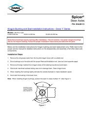
<strong>Wheel</strong> <strong>Differential</strong> <strong>Bearing</strong> <strong>Adjustment</strong> <strong>Tool</strong> <strong>Kit</strong> <strong>Instructions</strong><br />
<strong>Spicer</strong> ®<br />
Axles & Brakes<br />
P/N: SHAIS150<br />
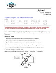
Shown below is a complete set of instructions on how to properly utilize Dana’s <strong>Wheel</strong> <strong>Differential</strong> <strong>Bearing</strong><br />
<strong>Adjustment</strong> tool. This installation tool kit is necessary to properly set up the ring gear pattern, set the<br />
differential bearing preload and complete the installation of the wheel differential assembly. This tool kit will<br />
allow you to align the threaded bearing cups during the assembly of the carrier. Additionally it will gage the<br />
adjustment for the differential bearing preload and assist in setting the primary gearing backlash. Refer to<br />
Dana Service Manual AXSM-0057 for any additional carrier set-up information.<br />
Models: All D170/S170 and D190/S190 Drive Axles<br />
<strong>Wheel</strong> <strong>Differential</strong> <strong>Bearing</strong> <strong>Adjustment</strong> <strong>Kit</strong> Part Number – 513061<br />
<strong>Kit</strong> Content: 2 - 130971 <strong>Wheel</strong> Diff. <strong>Bearing</strong> Adjuster Plate<br />
1 - 130997 ½” –13 Threaded Rod<br />
2 - 130998 ½” –13 Nuts<br />
2 - HN115 Flat Washers<br />
1 - SHAIS150 Instruction Sheet<br />
<strong>Instructions</strong>:<br />
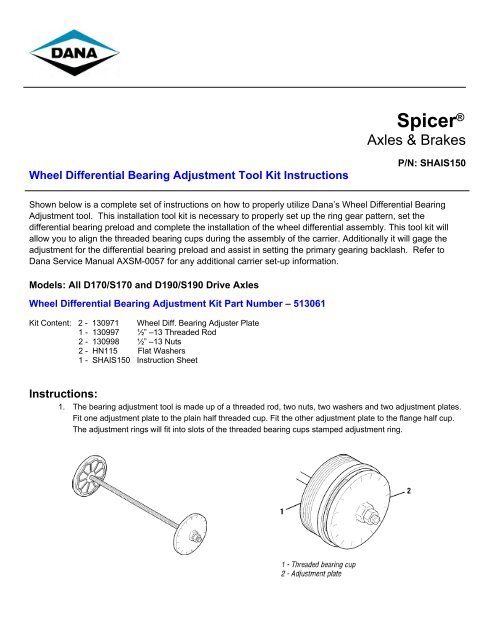
1. The bearing adjustment tool is made up of a threaded rod, two nuts, two washers and two adjustment plates.<br />
Fit one adjustment plate to the plain half threaded cup. Fit the other adjustment plate to the flange half cup.<br />
The adjustment rings will fit into slots of the threaded bearing cups stamped adjustment ring.
2. Connect the adjuster plates using the threaded rod, washers and nuts. Tighten the nuts on the rod to hold the<br />
threaded cups in place. Carefully lower the wheel differential and ring gear assembly into the carrier.<br />
Note: There are two ways to make sure that the threaded cups are seated properly. If there is a misalignment,<br />
reinstall the differential assembly at a slightly different angle.<br />
3. Make sure there is no gap between the carrier threads and the cup threads.<br />
4. Make sure that the bearings cage is parallel to the edge of the threaded cup.
5. Use a ratchet or breaker bar and a 1 ¼” deep wall socket to turn the flange half threaded bearing cup in until<br />
the ring gear contacts the pinion (zero backlash). Back the cup out two notches of the adjustment plate.<br />
6. Turn the plain half adjuster ring until there is zero preload on the bearings. This is done by turning the adjuster<br />
plate clockwise until you feel the threaded cup gain resistance. The threaded bearing cup should only be<br />
slightly snugged to achieve a zero preload condition.<br />
7. Obtain two notches of preload by tightening the plain half adjustment plate two notches. Start with the notch<br />
at the top, count two notches counter-clockwise on the adjuster plate. Turn the adjuster plate so that the<br />
notch is facing straight up.
8. Use a rubber mallet to fully seat the threaded bearing cups.<br />
9. With a dial indicator, check the ring and pinion backlash. Set the backlash from 0.010" to 0.012". This will give<br />
you room to adjust the contact pattern, if necessary.<br />
10. Remover the adjuster plates and threaded rod assembly.<br />
11. Install the carrier differential bearing caps and capscrews. Make curtain there is no gap between the carrier<br />
cap and the carrier surface.
12. Use an impact gun to securely fasten down the (4) carrier cap fasteners.<br />
Note: Do not completely torque them down at this point.<br />
13. Recheck the backlash.<br />
a. New Gearing: The backlash should be between 0.008" and 0.018" (0.20 and 0.46 mm).<br />
b. Used Gearing: The backlash should be reset to what it was at the time of disassembly.<br />
Note: If you have too much backlash, move the ring gear closer to the pinion. Count the number of notches you<br />
back off the plain half threaded cup. Each notch equals about 0.003" (0.08 mm) of backlash.<br />
IMPORTANT: In order to maintain the differential bearing preload, you will need to turn the flange half threaded<br />
cup the same amount in the same direction. If you need more backlash, reverse the procedure.<br />
14. After the gear pattern is correctly set. Torque the carrier cap fasteners as specified below.<br />
M20 X 1.5 X 90 = 385 – 435 ft. lbs (521 – 589 n.m)<br />
M18 X 1.5 X 85 = 325 – 375 ft. lbs. (440 – 508 n.m)<br />
M16 X 1.5 X 85 = 215 – 245 ft. lbs. (291 – 332 n.m)<br />
For spec’ing or service assistance, call 1-800-621-8084 24 hours a day, 7 days a week.<br />
Or visit our web site at: http://www.spicerparts.com<br />
Dana Corporation<br />
SHAIS150A Copyright Dana Corporation, 2003 Commercial Vehicle Axle Division<br />
October 2003 All Rights Reserved. P.O. Box 321<br />
Printed in U.S.A. www.dana.com Toledo, Ohio 43697-0321