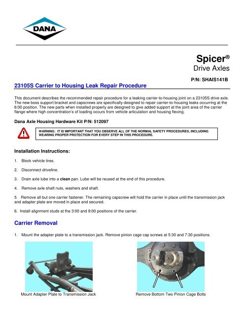
23105S Carrier to Housing Leak Repair Procedure - Spicer
23105S Carrier to Housing Leak Repair Procedure - Spicer
23105S Carrier to Housing Leak Repair Procedure - Spicer

Create successful ePaper yourself
Turn your PDF publications into a flip-book with our unique Google optimized e-Paper software.
<strong>23105S</strong> <strong>Carrier</strong> <strong>to</strong> <strong>Housing</strong> <strong>Leak</strong> <strong>Repair</strong> <strong>Procedure</strong><br />
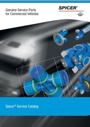
<strong>Spicer</strong> ®<br />
Drive Axles<br />
P/N: SHAIS141B<br />
This document describes the recommended repair procedure for a leaking carrier-<strong>to</strong>-housing joint on a <strong>23105S</strong> drive axle.<br />
The new boss support bracket and capscrews are specifically designed <strong>to</strong> repair carrier-<strong>to</strong>-housing leaks occurring at the<br />
6:00 position. The new parts when installed properly are designed <strong>to</strong> give added support at the joint area of the carrier<br />
flange where high concentration’s of loading occurs from vehicle articulation and housing flexing.<br />
Dana Axle <strong>Housing</strong> Hardware Kit P/N: 512097<br />
Installation Instructions:<br />
1. Block vehicle tires.<br />
2. Disconnect driveline.<br />
3. Drain axle lube in<strong>to</strong> a clean pan. Lube will be reused at the end of this procedure.<br />
4. Remove axle shaft nuts, washers and shaft.<br />
5. Remove all but one carrier fastener. The remaining capscrew will hold the carrier in place until the transmission jack<br />
and adapter plate are moved in place and secured.<br />
6. Install alignment studs at the 3:00 and 9:00 positions of the carrier.<br />
<strong>Carrier</strong> Removal<br />
WARNING: IT IS IMPORTANT THAT YOU OBSERVE ALL OF THE NORMAL SAFETY PROCEDURES, INCLUDING<br />
WEARING PROPER PROTECTION FOR EVERY STEP IN THIS PROCEDURE.<br />
1. Mount the adapter plate <strong>to</strong> a transmission jack. Remove pinion cage cap screws at 5:30 and 7:30 positions.<br />
Mount Adapter Plate <strong>to</strong> Transmission Jack Remove Bot<strong>to</strong>m Two Pinion Cage Bolts
2. Position the adapter plate and adjust transmission jack table <strong>to</strong> alien bolt holes.<br />
3. To fasten the adapter plate <strong>to</strong> the pinion cage install 2 HCS ¾” x 3” capscrews and snug with impact gun.<br />
Position Adapter Plate Install ¾” x 3” Capscrews<br />
4. Remove remaining carrier <strong>to</strong> housing capscrew and carefully remove the carrier assembly.<br />
<strong>Carrier</strong> Flange and <strong>Housing</strong> Ring Cleaning<br />
Note: Before installing new fastener hardware or the carrier assembly, inspect the axle housing visually for<br />
cracks, nicks or burrs on all machined surfaces. It is important that all surfaces are cleaned properly.<br />
1. Use a wire wheel <strong>to</strong> remove any paint, old sealant or oil from the housing and carrier mounting surfaces. Wipe<br />
surfaces down with cleaning solvent <strong>to</strong> remove any residual oil or dirt.<br />
Wire Wheel Surfaces Check for Nick, Cracks and Contamination<br />
2. Apply a 1/8” bead of Loctite 5699 Ultra Grey or Dow Corning 3-0100 Au<strong>to</strong>motive Sealant <strong>to</strong> the housing surface, it’s<br />
important <strong>to</strong> apply the sealant around (make a loop) all of the threaded bolt holes.<br />
IMPORTANT: Do not spread or smooth-out RTV once applied. RTV will set in 20<br />
minutes. Install carrier before RTV sets or reapply.<br />
1/8” Bead of Approved RTV Make loop around all bolt holes
<strong>Carrier</strong> Reinstallation<br />
1. Adjust the Transmission jack <strong>to</strong> start the carrier on the guide pins.<br />
Note: The carrier may have moved forward when it was removed from the housing, the transmission jack<br />
table should be readjusted <strong>to</strong> compensate for this movement.<br />
2. It is important that the carrier is at the same angle as the housing. The gap between the carrier flange and the housing<br />
ring should be the same all the way around.<br />
Adjust Jack <strong>to</strong> Start <strong>Carrier</strong> on Guide Pins Same Gap Top-<strong>to</strong>-Bot<strong>to</strong>m and Right-<strong>to</strong>-Left<br />
3. Raise or lower the assembly until it slides in<strong>to</strong> place. If it does not slide in easy, check the carrier-<strong>to</strong>-housing<br />
alignment. Right-<strong>to</strong>-left, <strong>to</strong>p-<strong>to</strong>-bot<strong>to</strong>m.<br />
4. Disconnect carrier adapter plate. Apply Loctite 277 <strong>to</strong> the threads of the original pinion cage capscrews, reinstall and<br />
<strong>to</strong>rque <strong>to</strong> 240 – 300 ft. lbs.<br />
Apply Loctite 277 Reinstall Capscrews<br />
5. Install at least one of the new carrier fasteners <strong>to</strong> hold the carrier in place so you can remove the alignment studs.<br />
6. Remove the alignment studs.<br />
7. Install new carrier <strong>to</strong> housing fasteners <strong>to</strong> all but the bot<strong>to</strong>m two positions. The 5:30 and 6:30 positions will utilize two<br />
unique 3” long capscrew <strong>to</strong> mount the boss support bracket.
8. Position the boss support bracket so that the side with the machined raised area is facing the carrier flange surface.<br />
Boss Support Bracket Raised Area Faces the <strong>Carrier</strong> Flange<br />
9. Install two 3” long capscrew, and <strong>to</strong>rque <strong>to</strong> 250 –270 ft. lbs.<br />
10. Torque remaining carrier <strong>to</strong> housing fasteners in a crisscross pattern <strong>to</strong> 250 – 270 ft. lbs.<br />
11. Clean axle shaft flanges and wheel hub surfaces and install new axle shaft gasket.<br />
12. Reinstall the axle shaft, washers and nuts, <strong>to</strong>rque <strong>to</strong> spec.<br />
13. Reinstall the driveline.<br />
Raised Area<br />
14. Remove fill plug from housing cover and refill the housing using the same lubricant that was removed. If needed, add<br />
lube and fill until level with the bot<strong>to</strong>m of the fill hole.<br />
Copyright Dana Limited, 2013 Dana Aftermarket Group<br />
SHAIS141B JFEB 2013 All Rights Reserved. P.O. Box 321<br />
Printed in U.S.A. Dana Limited Toledo, OH 43697-0321