Broschüre Schalungen e
Broschüre Schalungen e
Broschüre Schalungen e

You also want an ePaper? Increase the reach of your titles
YUMPU automatically turns print PDFs into web optimized ePapers that Google loves.
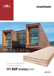
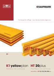
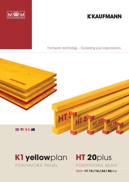
FORMWORK PANEL<br />
Formwork technology – Exceeding your expectations.<br />
K1 yellowplan HT 20plus<br />
FORMWORK BEAM<br />
NEW: HT 12 / 16 / 24 / 30plus
FORMWORK TECHNOLOGY<br />
Contents<br />
HT plus formwork beams<br />
Properties 4<br />
Technical data 6<br />
HT 12plus<br />
Technical data 8<br />
Span table 9<br />
HT 16plus<br />
Technical data 10<br />
Span table 11<br />
HT 20plus<br />
Technical data 12<br />
Span table 13<br />
HT 24plus<br />
Technical data 14<br />
Span table 15<br />
HT 30plus<br />
Technical data 16<br />
Span table 17<br />
2 Mayr-Melnhof Kaufmann<br />
K1 yellowplan formwork panels<br />
Properties 18<br />
Technical data 20<br />
Quality 21<br />
Company / Products / Markets 22<br />
Version 1 / 2011
Version 1 / 2011<br />
K1 yellowplan HT 20plus<br />
Formwork technology that exceeds your<br />
expectations<br />
The HT 20plus formwork beam and formwork panels K1 yellow -<br />
plan from Mayr-Melnhof Kaufmann are globally established<br />
brand products for concrete construction.<br />
As pioneers and quality leaders in formwork and engineered<br />
timber construction, we have been producing these products<br />
for over 50 years at our Reuthe production facility in Austria's<br />
Bregenzer wald region.<br />
Thanks to their remarkable quality, our formwork products<br />
are used in over 60 countries. Mayr-Melnhof Kaufmann is<br />
today one of the leading companies in the industry.<br />
Mayr-Melnhof Kaufmann 3
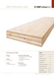
PROPERTIES<br />
Chords made of high-quality,<br />
specially graded solid timber<br />
The shock-resistant, bevelled<br />
protective cap made of synthetic<br />
materials provides protection from<br />
splintering at the chord ends,<br />
signifi cantly increasing the durability<br />
Webs made of 3-ply laminated<br />
solid wood panels ensure high<br />
carrying capacity for continuous<br />
use in all climate zones<br />
Indestructible fi nger jointing<br />
between chord and web<br />
The concrete formwork beam with the globally<br />
proven protective cap system<br />
HT 20plus is the global brand for the concrete formwork<br />
beam from Mayr-Melnhof Kaufmann. High-quality materials,<br />
fl awless workmanship, and the globally proven protective cap<br />
system give the HT plus formwork beams their unsurpassed<br />
lifecycle. HT 20plus stands for top quality in construction.<br />
For some 50 years, the HT 20plus formwork beam from Mayr-<br />
Melnhof Kaufmann has been developing one of the leading<br />
brands in concrete construction. With its robustness and exceptional<br />
lifecycle, the HT 20plus enjoys an elite reputation<br />
among industry experts.<br />
4 Mayr-Melnhof Kaufmann<br />
In 2010 the product spectrum of the HT 20plus was expanded<br />
with the addition of four new beam types, the HT 12plus,<br />
HT 16plus, HT 24plus, and HT 30plus.<br />
The range of our current product line allows for specifi -<br />
cally tailored applications of our formwork beams. The ability<br />
to select the optimal beam type allows structural engineers,<br />
technicians, and project managers to further improve<br />
effi ciency.<br />
Version 1 / 2011
Version 1 / 2011<br />
HT plus formwork beams<br />
The length and production date printed<br />
on top of the chord provide a unique<br />
labelling of the HT plus formwork beams<br />
Mayr-Melnhof Kaufmann 5
TECHNICAL DATA<br />
6 Mayr-Melnhof Kaufmann<br />
Version 1 / 2011
Product<br />
Wood species<br />
Wood moisture<br />
Gluing<br />
Chord<br />
Webs<br />
Surface protection<br />
Support<br />
Packaging<br />
Product overview<br />
Version 1 / 2011<br />
Wooden formwork beams, glued, solid-walled I-beams<br />
Spruce, fi r, mixed types available<br />
12 % +/- 3 % at delivery<br />
Melamine resin-based adhesive, adhesive type I EN 301-approved for gluing<br />
of load-bearing wood structural elements.<br />
• Visually graded to strength class S10 acc. to DIN 4074<br />
• Finger-jointed, high-grade, solid whitewood, fi ngerjoints acc. to DIN 68140-1<br />
• Chords are grooved on the side turned away from the core (left side of chord surface)<br />
• Smoothly surfaced and chamfered to approx. 4 mm<br />
• Solid wooden panel for structural and exterior application acc. to EN 13353<br />
• Primarily vertical growth rings in outer and middle layer<br />
Treatment of entire beam using a water-resistant color stain.<br />
Due to the 3-ply solid wood webs, HT plus formwork beams can be cut into and supported<br />
at any length.<br />
The packages are delivered suitable for the construction site and protected by integrated<br />
supporting timber.<br />
Formwork beam HT 12plus HT 16plus HT 20plus HT 24plus HT 30plus<br />
Weight and dimensions<br />
Beam height 120 mm 160 mm 200 mm 240 mm 300 mm<br />
Chord height 35 mm 35 mm 40 mm 40 mm 57 mm<br />
Chord width 65 mm 65 mm 80 mm 80 mm 96 mm<br />
Web thickness 26,6 mm 26,6 mm 26,6 mm 26,6 mm 26,6 mm<br />
Weight 2,8 kg/m 3,3 kg/m 4,6 kg/m 5,1 kg/m 7,6 kg/m<br />
Calculated values<br />
EI MOE x moment of inertia 97 kNm² 212 kNm² 486 kNm² 775 kNm² 1906 kNm²<br />
E Chord Modulus of elasticity chord (C24) 11.000 N/mm² 11.000 N/mm² 11.000 N/mm² 11.000 N/mm² 11.000 N/mm²<br />
E Web Modulus of elasticity web (3-ply panel) 6.700 N/mm² 6.700 N/mm² 6.700 N/mm² 6.700 N/mm² 6.700 N/mm²<br />
V k Characteristic value of lateral force 15,3 kN 18,4 kN 23,9 kN 28,2 kN 34,5 kN<br />
R b,k Characteristic value of supporting 29,4 kN 36,8 kN 47,8 kN 56,4 kN 69 kN<br />
M k Moment 4,4 kNm 5,9 kNm 10,9 kNm 14,1 kNm 26,2 kNm<br />
Quality-monitored production FPC FPC FPC + MPA FPC FPC<br />
FPC = Internal factory production control / MPA = External monitoring by Material Testing Institute in Stuttgart<br />
Carrying capacity values for the construction site<br />
Conversion of characteristic value for permissible measurement value using old measurement concept according to EN 13377 Appendix E<br />
X d = k mod x X k / γ m<br />
X d Rated value of material property<br />
X k Characteristic value of material property<br />
k mod Modifi cation value of wood moisture
HT 12plus TECHNICAL DATA<br />
Dimensions<br />
and tolerances<br />
Product standard<br />
Calculated values<br />
Standard lengths<br />
Weight<br />
Package units<br />
120 mm<br />
8 Mayr-Melnhof Kaufmann<br />
65 mm<br />
35 mm<br />
Dimensions HT 12plus Tolerances<br />
Beam height 120 mm + / - 2,0 mm<br />
Chord thickness 35 mm - 1,5 %<br />
Chord width 65 mm - 1,5 %<br />
Web thickness 26,6 mm + / - 0,5 mm<br />
Industrially manufactured formwork timber beams are to be used in supporting structures and<br />
formworks for concrete buildings. The load is applied in the direction of the formwork beam<br />
height. The EN 13377 standard specifi es the classifi cation, the requirements, and verifi cation<br />
procedures for form work beams in the heights h = 16, h = 20 and h = 24 cm. We have derived<br />
the calculated values for the height h = 12 cm from this standard and confi rmed it in tests.<br />
According to EN13377 Carrying capacity characteristics<br />
Lateral force V k = 15,3 kN permissible Q = 7 kN<br />
Bending moment M k = 4,4 kNm permissible M = 2,1 kNm<br />
Reaction of support R b,k = 29,4 kN<br />
MOE x moment of inertia EI = 97 kNm²<br />
Elasticity module of chord (C24) E Chord = 11.000 N/mm²<br />
Elasticity module of web (SWP) E Web = 6.700 N/mm²<br />
2,45 / 2,50 / 2,65 / 2,90 / 3,30 / 3,60 / 3,90 / 4,20 / 4,50 / 4,90 / max. 5,00 m<br />
2,8 kg/m<br />
Standard package: 144 pieces<br />
Version 1 / 2011
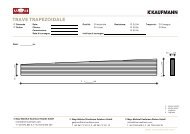
Deflection [mm]<br />
Deflection [mm]<br />
SPAN TABLE<br />
Single-span beam<br />
8,0<br />
7,0<br />
6,0<br />
5,0<br />
4,0<br />
3,0<br />
2,0<br />
1,0<br />
0,0<br />
0,0 2,5 5,0 7,5 10,0<br />
Capacity [kN/m]<br />
Multi-span beam<br />
8,0<br />
7,0<br />
6,0<br />
5,0<br />
4,0<br />
3,0<br />
2,0<br />
1,0<br />
0,0<br />
0,0 2,5 5,0 7,5 10,0<br />
Capacity [kN/m]<br />
Sample calculation<br />
Version 1 / 2011<br />
l = 1,25 m<br />
l = 1,50 m<br />
l = 1,75 m<br />
l = 2,00 m<br />
l = 2,25 m<br />
l = 2,50 m<br />
l = 2,75 m<br />
permissible M<br />
permissible Q<br />
permissible f<br />
Table 1: Crossbeams<br />
Distance between crossbeams (m)<br />
HT 12plus<br />
Table 2: Main beams<br />
Selected distance between main beams (m)<br />
0.3 0.4 0.5 0.625 0.675 0.75 0.875 1 1.25 1.5 1.75 2 2.25<br />
Floor thickness Total load<br />
cm<br />
KN / m2 Max. support width of crossbeam<br />
Max. permissible support width<br />
= Max. distance between main beams<br />
= Distance between supports<br />
10 4.60 2.52 2.29 2.13 1.97 1.92 1.86 1.76 1.69 1.57 1.47 1.40 1.32 1.24<br />
12 5.12 2.39 2.18 2.02 1.87 1.83 1.76 1.68 1.60 1.49 1.40 1.33 1.25 1.18<br />
14 5.64 2.29 2.08 1.93 1.79 1.75 1.69 1.60 1.53 1.42 1.34 1.27 1.19 1.10<br />
16 6.16 2.20 2.00 1.86 1.72 1.68 1.62 1.54 1.47 1.37 1.29 1.22 1.14 1.01<br />
18 6.68 2.12 1.93 1.79 1.66 1.62 1.57 1.49 1.42 1.32 1.24 1.17 1.05 0.93<br />
20 7.20 2.06 1.87 1.74 1.61 1.57 1.52 1.44 1.38 1.28 1.20 1.11 0.97 0.86<br />
22 7.72 2.00 1.82 1.69 1.56 1.53 1.47 1.40 1.34 1.24 1.17 1.04 0.91 0.81<br />
24 8.24 1.95 1.77 1.64 1.52 1.49 1.43 1.36 1.30 1.21 1.13 0.97 0.85 0.76<br />
26 8.76 1.90 1.72 1.60 1.49 1.45 1.40 1.33 1.27 1.18 1.07 0.91 0.80 0.71<br />
28 9.28 1.86 1.69 1.56 1.45 1.42 1.37 1.30 1.24 1.15 1.01 0.86 0.75 0.67<br />
30 9.80 1.82 1.65 1.53 1.42 1.39 1.34 1.27 1.22 1.13 0.95 0.82 0.71 0.63<br />
32 10.37 1.78 1.62 1.50 1.39 1.36 1.31 1.25 1.19 1.08 0.90 0.77 0.68 0.60<br />
34 10.94 1.75 1.59 1.47 1.37 1.33 1.29 1.22 1.17 1.02 0.85 0.73 0.64 0.57<br />
36 11.51 1.71 1.56 1.45 1.34 1.31 1.26 1.20 1.15 0.97 0.81 0.70 0.61 0.54<br />
38 12.08 1.69 1.53 1.42 1.32 1.29 1.24 1.18 1.13 0.93 0.77 0.66 0.58 0.52<br />
40 12.65 1.66 1.51 1.40 1.30 1.27 1.22 1.16 1.11 0.89 0.74 0.63 0.55 0.49<br />
45 14.08 1.60 1.45 1.35 1.25 1.22 1.18 1.12 0.99 0.80 0.66 0.57 0.50 0.44<br />
50 15.50 1.54 1.40 1.30 1.21 1.18 1.14 1.03 0.90 0.72 0.60 0.52 0.45 0.40<br />
Required: Distance between main beams and between supports<br />
Available: 20 cm concrete thickness with total load of 7.20 kN/m 2<br />
Selected: Distance between crossbeams of 0.5 m<br />
Result: 1.74 m distance between main beams<br />
(select next larger distance between main beams, here 1.75 m)<br />
1.11 m distance between supports (check carrying capacity of supports)<br />
Mayr-Melnhof Kaufmann 9
HT 16plus TECHNICAL DATA<br />
Dimensions<br />
and tolerances<br />
Product standard<br />
Calculated values<br />
Standard lengths<br />
Weight<br />
Package units<br />
10 Mayr-Melnhof Kaufmann<br />
160 mm<br />
65 mm<br />
35 mm<br />
Dimensions HT 16plus Tolerances<br />
Beam height 160 mm + / - 2,0 mm<br />
Chord thickness 35 mm - 1,5 %<br />
Chord width 65 mm - 1,5 %<br />
Web thickness 26,6 mm + / - 0,5 mm<br />
Industrially manufactured formwork timber beams are to be used in supporting structures and<br />
formworks for concrete buildings. The load is applied in the direction of the formwork beam<br />
height.<br />
The EN 13377 standard specifi es the classifi cation, the requirements, and verifi cation procedures<br />
for formwork beams in the heights h = 16, h = 20 and h = 24 cm.<br />
According to EN13377 Carrying capacity characteristics<br />
Lateral force V k = 18,4 kN permissible Q = 8,5<br />
Bending moment M k = 5,9 kNm permissible M = 2,7<br />
Reaction of support R b,k = 36,8 kN<br />
MOE x moment of inertia EI = 212 kNm²<br />
Elasticity module of chord (C24) E Chord = 11.000 N/mm²<br />
Elasticity module of web (SWP) E Web = 6.700 N/mm²<br />
2,45 / 2,50 / 2,65 / 2,90 / 3,30 / 3,60 / 3,90 / 4,20 / 4,50 / 4,90 / 5,90 / max. 8,00 m<br />
3,3 kg/m<br />
Standard package: 150 pieces<br />
Version 1 / 2011
Deflection [mm]<br />
Deflection [mm]<br />
SPAN TABLE<br />
Single-span beam<br />
8,0<br />
7,0<br />
6,0<br />
5,0<br />
4,0<br />
3,0<br />
2,0<br />
1,0<br />
0,0<br />
0,0 2,5 5,0 7,5 10,0 12,5 15,0<br />
Capacity [kN/m]<br />
Multi-span beam<br />
8,0<br />
7,0<br />
6,0<br />
5,0<br />
4,0<br />
3,0<br />
2,0<br />
1,0<br />
0,0<br />
0,0 2,5 5,0 7,5 10,0 12,5 15,0<br />
Capacity [kN/m]<br />
Version 1 / 2011<br />
Table 1: Crossbeams<br />
Distance between crossbeams (m)<br />
HT 16plus<br />
Table 2: Main beams<br />
Selected distance between main beams (m)<br />
0.4 0.5 0.625 0.675 0.75 1 1.25 1.5 1.75 2 2.25 2.5 3<br />
Floor thickness Total load<br />
cm<br />
KN / m2 Max. support width of crossbeam<br />
Max. permissible support width<br />
= Max. distance between main beams<br />
= Distance between supports<br />
10 4.60 2.97 2.76 2.56 2.50 2.41 2.17 1.94 1.77 1.64 1.53 1.44 1.37 1.22<br />
12 5.12 2.82 2.62 2.43 2.37 2.29 2.05 1.84 1.68 1.55 1.45 1.37 1.30 1.09<br />
14 5.64 2.70 2.51 2.33 2.27 2.19 1.96 1.75 1.60 1.48 1.38 1.30 1.19 0.99<br />
16 6.16 2.59 2.41 2.24 2.18 2.10 1.87 1.67 1.53 1.42 1.32 1.21 1.09 0.91<br />
18 6.68 2.50 2.33 2.16 2.10 2.03 1.80 1.61 1.47 1.36 1.26 1.12 1.01 0.84<br />
20 7.20 2.43 2.25 2.09 2.04 1.97 1.73 1.55 1.41 1.31 1.17 1.04 0.93 0.78<br />
22 7.72 2.36 2.19 2.03 1.98 1.91 1.67 1.50 1.37 1.24 1.09 0.97 0.87 0.73<br />
24 8.24 2.29 2.13 1.98 1.93 1.86 1.62 1.45 1.32 1.17 1.02 0.91 0.82 0.68<br />
26 8.76 2.24 2.08 1.93 1.88 1.81 1.57 1.40 1.28 1.10 0.96 0.85 0.77 0.64<br />
28 9.28 2.19 2.03 1.88 1.84 1.76 1.53 1.36 1.21 1.03 0.91 0.80 0.72 0.60<br />
30 9.80 2.14 1.99 1.84 1.80 1.71 1.48 1.33 1.14 0.98 0.86 0.76 0.69 0.57<br />
32 10.37 2.10 1.95 1.81 1.76 1.67 1.44 1.29 1.08 0.93 0.81 0.72 0.65 0.54<br />
34 10.94 2.06 1.91 1.77 1.71 1.62 1.41 1.23 1.02 0.88 0.77 0.68 0.61 0.51<br />
36 11.51 2.02 1.88 1.73 1.67 1.58 1.37 1.17 0.97 0.83 0.73 0.65 0.58 0.49<br />
38 12.08 1.99 1.84 1.69 1.63 1.54 1.34 1.11 0.93 0.79 0.70 0.62 0.56 0.46<br />
40 12.65 1.95 1.81 1.65 1.59 1.51 1.31 1.06 0.89 0.76 0.66 0.59 0.53 0.44<br />
45 14.08 1.88 1.75 1.57 1.51 1.43 1.19 0.95 0.80 0.68 0.60 0.53 0.48 0.40<br />
50 15.50 1.82 1.67 1.49 1.44 1.36 1.08 0.87 0.72 0.62 0.54 0.48 0.43 0.36<br />
55 16.93 1.77 1.60 1.43 1.38 1.30 0.99 0.79 0.66 0.57 0.50 0.44 0.40 0.33<br />
60 18.35 1.72 1.53 1.37 1.32 1.22 0.92 0.73 0.61 0.52 0.46 0.41 0.37 0.31<br />
65 19.78 1.65 1.48 1.32 1.26 1.13 0.85 0.68 0.57 0.49 0.42 0.38 0.34 0.28<br />
70 21.20 1.60 1.43 1.27 1.17 1.06 0.79 0.63 0.53 0.45 0.40 0.35 0.32 0.26<br />
Sample calculation<br />
l = 1,25 m<br />
l = 1,50 m<br />
l = 1,75 m<br />
l = 2,00 m<br />
l = 2,25 m<br />
l = 2,50 m<br />
l = 2,75 m<br />
permissible M<br />
permissible Q<br />
permissible f<br />
Required: Distance between main beams and between supports<br />
Available: 24 cm concrete thickness with total load of 8.24 kN/m 2<br />
Selected: Distance between crossbeams of 0.625 m<br />
Result: 1.98 m distance between main beams<br />
(select next larger distance between main beams, here 2 m)<br />
1.02 m distance between supports (check carrying capacity of supports)<br />
Mayr-Melnhof Kaufmann 11
HT 20plus TECHNICAL DATA<br />
Dimensions<br />
and tolerances<br />
Product standard<br />
Calculated values<br />
Standard lengths<br />
Weight<br />
Package units<br />
12 Mayr-Melnhof Kaufmann<br />
200 mm<br />
80 mm<br />
Industrially manufactured formwork timber beams are to be used in supporting structures<br />
and formworks for concrete buildings. The load is applied in the direction of the formwork<br />
beam height. The EN 13377 standard specifi es the classifi cation, the requirements, and<br />
verifi cation procedures for formwork beams in the heights h = 16, h = 20 and h = 24 cm.<br />
The formwork timber beam HT20Plus is marked with an Ü stamp according the Technical<br />
Approval Z 9.1-146 by the Institute of structural engineering, Berlin (DIBt) until July 2012.<br />
2,45 / 2,50 / 2,65 / 2,90 / 3,30 / 3,60 / 3,90 / 4,20 / 4,50 / 4,90 / 5,90 / max. 10,00 m<br />
4,6 kg/m<br />
40 mm<br />
Standard package: 60 pieces<br />
Dimensions HT 20plus Tolerances<br />
Beam height 200 mm + / - 2,0 mm<br />
Chord thickness 40 mm - 1,5 %<br />
Chord width 80 mm - 1,5 %<br />
Web thickness 26,6 mm + / - 0,5 mm<br />
According to EN13377 Carrying capacity characteristics<br />
Lateral force V k = 23,9 kN permissible Q = 11 kN<br />
Bending moment M k = 10,9 kNm permissible M = 5 kNm<br />
Reaction of support R b,k = 47,8 kN<br />
MOE x moment of inertia EI = 486 kNm²<br />
Elasticity module of chord (C24) E Chord = 11.000 N/mm²<br />
Elasticity module of web (SWP) E Web = 6.700 N/mm²<br />
Container package: 100 pieces<br />
Version 1 / 2011
Deflection [mm]<br />
Deflection [mm]<br />
6,0<br />
5,0<br />
4,0<br />
3,0<br />
2,0<br />
1,0<br />
SPAN TABLE<br />
0,0<br />
0,0 2,5 5,0 7,5 10,0 12,5 15,0 17,5 20,0<br />
Capacity [kN/m]<br />
6,0<br />
5,0<br />
4,0<br />
3,0<br />
2,0<br />
1,0<br />
Single-span beam<br />
Multi-span beam<br />
0,0<br />
0,0 2,5 5,0 7,5 10,0 12,5 15,0 17,5 20,0<br />
Capacity [kN/m]<br />
Sample calculation<br />
Version 1 / 2011<br />
l = 1,25 m<br />
l = 1,50 m<br />
l = 1,75 m<br />
l = 2,00 m<br />
l = 2,25 m<br />
l = 2,50 m<br />
l = 2,75 m<br />
permissible M<br />
permissible Q<br />
permissible f<br />
Table 1: Crossbeams<br />
Distance between crossbeams (m)<br />
HT 20plus<br />
Table 2: Main beams<br />
Selected distance between main beams (m)<br />
0.5 0.625 0.675 0.75 1 1.25 1.5 1.75 2 2.25 2.5 3 3.5<br />
Floor thickness Total load<br />
cm<br />
KN / m2 Max. support width of crossbeam<br />
Max. permissible support width<br />
= Max. distance between main beams<br />
= Distance between supports<br />
10 4.60 3.64 3.38 3.29 3.18 2.89 2.64 2.41 2.23 2.09 1.97 1.87 1.59 1.37<br />
12 5.12 3.46 3.21 3.13 3.02 2.74 2.50 2.28 2.11 1.98 1.86 1.72 1.43 1.23<br />
14 5.64 3.30 3.07 2.99 2.89 2.62 2.38 2.17 2.01 1.88 1.73 1.56 1.30 1.11<br />
16 6.16 3.18 2.95 2.87 2.77 2.52 2.28 2.08 1.93 1.79 1.59 1.43 1.19 1.02<br />
18 6.68 3.07 2.85 2.77 2.68 2.43 2.19 2.00 1.85 1.65 1.46 1.32 1.10 0.94<br />
20 7.20 2.97 2.76 2.69 2.59 2.36 2.11 1.92 1.75 1.53 1.36 1.22 1.02 0.87<br />
22 7.72 2.88 2.68 2.61 2.52 2.28 2.04 1.86 1.63 1.42 1.27 1.14 0.95 0.81<br />
24 8.24 2.81 2.61 2.54 2.45 2.20 1.97 1.78 1.53 1.33 1.19 1.07 0.89 0.76<br />
26 8.76 2.74 2.54 2.48 2.39 2.14 1.91 1.67 1.44 1.26 1.12 1.00 0.84 0.72<br />
28 9.28 2.68 2.49 2.42 2.34 2.08 1.86 1.58 1.35 1.19 1.05 0.95 0.79 0.68<br />
30 9.80 2.62 2.43 2.37 2.29 2.02 1.80 1.50 1.28 1.12 1.00 0.90 0.75 0.64<br />
35 11.23 2.50 2.32 2.26 2.18 1.89 1.57 1.31 1.12 0.98 0.87 0.78 0.65 0.56<br />
40 12.65 2.39 2.22 2.16 2.05 1.74 1.39 1.16 0.99 0.87 0.77 0.70 0.58 0.50<br />
45 14.08 2.30 2.13 2.05 1.95 1.56 1.25 1.04 0.89 0.78 0.69 0.63 0.52 0.45<br />
50 15.50 2.23 2.03 1.96 1.85 1.42 1.14 0.95 0.81 0.71 0.63 0.57 0.47 0.41<br />
55 16.93 2.16 1.94 1.87 1.73 1.30 1.04 0.87 0.74 0.65 0.58 0.52 0.43 0.37<br />
60 18.35 2.09 1.87 1.78 1.60 1.20 0.96 0.80 0.69 0.60 0.53 0.48 0.40 0.34<br />
65 19.78 2.01 1.78 1.65 1.48 1.11 0.89 0.74 0.64 0.56 0.49 0.45 0.37 0.32<br />
70 21.20 1.94 1.66 1.54 1.38 1.04 0.83 0.69 0.59 0.52 0.46 0.42 0.35 0.30<br />
75 22.50 1.89 1.56 1.45 1.30 0.98 0.78 0.65 0.56 0.49 0.43 0.39 0.33 0.28<br />
80 23.80 1.83 1.48 1.37 1.23 0.92 0.74 0.62 0.53 0.46 0.41 0.37 0.31 0.26<br />
85 25.10 1.75 1.40 1.30 1.17 0.88 0.70 0.58 0.50 0.44 0.39 0.35 0.29 0.25<br />
90 26.40 1.67 1.33 1.23 1.11 0.83 0.67 0.56 0.48 0.42 0.37 0.33 0.28 0.24<br />
95 27.70 1.59 1.27 1.18 1.06 0.79 0.64 0.53 0.45 0.40 0.35 0.32 0.26 0.23<br />
100 29.00 1.52 1.21 1.12 1.01 0.76 0.61 0.51 0.43 0.38 0.34 0.30 0.25 0.22<br />
Required: Distance between main beams and between supports<br />
Available: 30 cm concrete thickness with total load of 9.80 kN/m 2<br />
Selected: Distance between crossbeams of 0.75 m<br />
Result: 2.29 m distance between main beams<br />
(select next larger distance between main beams, here 2.5 m)<br />
0.90 m distance between supports (check carrying capacity of supports)<br />
Mayr-Melnhof Kaufmann 13
HT 24plus<br />
Dimensions<br />
and tolerances<br />
Product standard<br />
Calculated values<br />
Standard lengths<br />
Weight<br />
Package units<br />
14 Mayr-Melnhof Kaufmann<br />
240 mm<br />
80 mm<br />
Dimensions HT 24plus Tolerances<br />
Beam height 240 mm + / - 2,0 mm<br />
Chord thickness 40 mm - 1,5 %<br />
Chord width 80 mm - 1,5 %<br />
Web thickness 26,6 mm + / - 0,5 mm<br />
Industrially manufactured formwork timber beams are to be used in supporting structures<br />
and formworks for concrete buildings. The load is applied in the direction of the formwork<br />
beam height.<br />
The EN 13377 standard specifi es the classifi cation, the requirements, and verifi cation procedures<br />
for formwork beams in the heights h = 16, h = 20 and h = 24 cm.<br />
According to EN13377 Carrying capacity characteristics<br />
Lateral force V k = 28,2 kN permissible Q = 13 kN<br />
Bending moment M k = 14,1 kNm permissible M = 6,5 kNm<br />
Reaction of support R b,k = 56,4 kN<br />
MOE x moment of inertia EI = 775 kNm²<br />
Elasticity module of chord (C24) E Chord = 11.000 N/mm²<br />
Elasticity module of web (SWP) E Web = 6.700 N/mm²<br />
TECHNICAL DATA<br />
2,45 / 2,50 / 2,65 / 2,90 / 3,30 / 3,60 / 3,90 / 4,20 / 4,50 / 4,90 / 5,90 / max. 10,00 m<br />
5,1 kg/m<br />
40 mm<br />
Standard package: 80 pieces<br />
Version 1 / 2011
Deflection [mm]<br />
Deflection [mm]<br />
6,0<br />
5,0<br />
4,0<br />
3,0<br />
2,0<br />
1,0<br />
SPAN TABLE<br />
Single-span beam<br />
0,0<br />
0,0 5,0 10,0 15,0 20,0 25,0<br />
Capacity [kN/m]<br />
Multi-span beam<br />
4,0<br />
3,5<br />
3,0<br />
2,5<br />
2,0<br />
1,5<br />
1,0<br />
0,5<br />
0,0<br />
0,0 2,5 5,0 7,5 10,0 12,5 15,0 17,5 20,0<br />
Capacity [kN/m]<br />
Sample calculation<br />
Version 1 / 2011<br />
l = 1,25 m<br />
l = 1,50 m<br />
l = 1,75 m<br />
l = 2,00 m<br />
l = 2,25 m<br />
l = 2,50 m<br />
l = 2,75 m<br />
permissible M<br />
permissible Q<br />
permissible f<br />
Table 1: Crossbeams<br />
Distance between crossbeams (m)<br />
HT 24plus<br />
Table 2: Main beams<br />
Selected distance between main beams (m)<br />
0.5 0.625 0.675 0.75 1 1.25 1.5 1.75 2 2.25 2.5 3 3.5<br />
Floor thickness Total load<br />
cm<br />
KN / m2 Max. support width of crossbeam<br />
Max. permissible support width<br />
= Max. distance between main beams<br />
= Distance between supports<br />
16 6.16 3.71 3.44 3.36 3.24 2.91 2.60 2.37 2.20 2.05 1.88 1.69 1.41 1.21<br />
18 6.68 3.58 3.33 3.24 3.13 2.79 2.50 2.28 2.11 1.95 1.73 1.56 1.30 1.11<br />
20 7.20 3.47 3.22 3.14 3.03 2.69 2.40 2.19 2.03 1.81 1.60 1.44 1.20 1.03<br />
22 7.72 3.37 3.13 3.05 2.94 2.60 2.32 2.12 1.92 1.68 1.50 1.35 1.12 0.96<br />
24 8.24 3.28 3.05 2.97 2.87 2.51 2.25 2.05 1.80 1.58 1.40 1.26 1.05 0.90<br />
26 8.76 3.20 2.97 2.90 2.80 2.44 2.18 1.98 1.70 1.48 1.32 1.19 0.99 0.85<br />
28 9.28 3.13 2.90 2.83 2.73 2.37 2.12 1.87 1.60 1.40 1.25 1.12 0.93 0.80<br />
30 9.80 3.06 2.84 2.77 2.66 2.30 2.06 1.77 1.52 1.33 1.18 1.06 0.88 0.76<br />
32 10.37 3.00 2.78 2.71 2.59 2.24 2.00 1.67 1.43 1.25 1.11 1.00 0.84 0.72<br />
34 10.94 2.94 2.73 2.65 2.52 2.18 1.90 1.58 1.36 1.19 1.06 0.95 0.79 0.68<br />
36 11.51 2.89 2.68 2.59 2.45 2.13 1.81 1.51 1.29 1.13 1.00 0.90 0.75 0.65<br />
38 12.08 2.84 2.62 2.53 2.40 2.07 1.72 1.43 1.23 1.08 0.96 0.86 0.72 0.61<br />
40 12.65 2.80 2.56 2.47 2.34 2.03 1.64 1.37 1.17 1.03 0.91 0.82 0.69 0.59<br />
45 14.08 2.69 2.43 2.34 2.22 1.85 1.48 1.23 1.06 0.92 0.82 0.74 0.62 0.53<br />
50 15.50 2.59 2.32 2.23 2.11 1.68 1.34 1.12 0.96 0.84 0.75 0.67 0.56 0.48<br />
55 16.93 2.48 2.22 2.13 2.02 1.54 1.23 1.02 0.88 0.77 0.68 0.61 0.51 0.44<br />
60 18.35 2.38 2.13 2.05 1.89 1.42 1.13 0.94 0.81 0.71 0.63 0.57 0.47 0.40<br />
65 19.78 2.29 2.05 1.95 1.75 1.31 1.05 0.88 0.75 0.66 0.58 0.53 0.44 0.38<br />
70 21.20 2.21 1.96 1.82 1.64 1.23 0.98 0.82 0.70 0.61 0.55 0.49 0.41 0.35<br />
75 22.50 2.15 1.85 1.71 1.54 1.16 0.92 0.77 0.66 0.58 0.51 0.46 0.39 0.33<br />
80 23.80 2.09 1.75 1.62 1.46 1.09 0.87 0.73 0.62 0.55 0.49 0.44 0.36 0.31<br />
85 25.10 2.04 1.66 1.53 1.38 1.04 0.83 0.69 0.59 0.52 0.46 0.41 0.35 0.30<br />
90 26.40 1.97 1.58 1.46 1.31 0.98 0.79 0.66 0.56 0.49 0.44 0.39 0.33 0.28<br />
95 27.70 1.88 1.50 1.39 1.25 0.94 0.75 0.63 0.54 0.47 0.42 0.38 0.31 0.27<br />
100 29.00 1.79 1.43 1.33 1.20 0.90 0.72 0.60 0.51 0.45 0.40 0.36 0.30 0.26<br />
Required: Distance between main beams and between supports<br />
Available: 36 cm concrete thickness with total load of 11.51 kN/m 2<br />
Selected: Distance between crossbeams of 0.75 m<br />
Result: 2.45 m distance between main beams<br />
(select next larger distance between main beams, here 2.5 m)<br />
0.90 m distance between supports (check carrying capacity of supports)<br />
Mayr-Melnhof Kaufmann 15
HT 30plus<br />
Dimensions<br />
and tolerances<br />
Product standard<br />
Calculated values<br />
Standard lengths<br />
Weight<br />
Package units<br />
16 Mayr-Melnhof Kaufmann<br />
300 mm<br />
96 mm<br />
Dimensions HT 30plus Tolerances<br />
Beam height 300 mm + / - 2,0 mm<br />
Chord thickness 57 mm - 1,5 %<br />
Chord width 96 mm - 1,5 %<br />
Web thickness 26,6 mm + / - 0,5 mm<br />
Industrially manufactured formwork timber beams are to be used in supporting structures and<br />
formworks for concrete buildings. The load is applied in the direction of the formwork beam<br />
height. The EN 13377 standard specifi es the classifi cation, the requirements, and verifi cation<br />
procedures for formwork beams in the heights h = 16, h = 20 and h = 24 cm. We have derived<br />
the calculated values for the height h = 30 cm from this standard and confi rmed it in tests.<br />
According to EN13377 Carrying capacity characteristics<br />
Lateral force V k = 34,5 kN permissible Q = 15 kN<br />
Bending moment M k = 26,2 kNm permissible M = 12 kNm<br />
Reaction of support R b,k = 69 kN<br />
MOE x moment of inertia EI = 1906 kNm²<br />
Elasticity module of chord (C24) E Chord = 11.000 N/mm²<br />
Elasticity module of web (SWP) E Web = 6.700 N/mm²<br />
TECHNICAL DATA<br />
2,45 / 2,50 / 2,65 / 2,90 / 3,30 / 3,60 / 3,90 / 4,20 / 4,50 / 4,90 / 5,90 / max. 6,00 m<br />
7,6 kg/m<br />
57 mm<br />
Standard package: 51 pieces<br />
Version 1 / 2011
Deflection [mm]<br />
Deflection [mm]<br />
6,0<br />
5,0<br />
4,0<br />
3,0<br />
2,0<br />
1,0<br />
0,0<br />
0,0 5,0 10,0 15,0 20,0 25,0 30,0<br />
Capacity [kN/m]<br />
3,0<br />
2,5<br />
2,0<br />
1,5<br />
1,0<br />
0,5<br />
SPAN TABLE<br />
Single-span beam<br />
Multi-span beam<br />
0,0<br />
0,0 5,0 10,0 15,0 20,0 25,0 30,0<br />
Capacity [kN/m]<br />
Sample calculation<br />
Version 1 / 2011<br />
l = 1,25 m<br />
l = 1,50 m<br />
l = 1,75 m<br />
l = 2,00 m<br />
l = 2,25 m<br />
l = 2,50 m<br />
l = 2,75 m<br />
permissible M<br />
permissible Q<br />
permissible f<br />
Table 1: Crossbeams<br />
Distance between crossbeams (m)<br />
HT 30plus<br />
Table 2: Main beams<br />
Selected distance between main beams (m)<br />
0.625 0.75 0.875 1 1.25 1.5 1.75 2 2.25 2.5 3 3.5 4<br />
Floor thickness Total load<br />
cm<br />
KN / m2 Max. support width of crossbeam<br />
Max. permissible support width<br />
= Max. distance between main<br />
= Distance between supports<br />
16 6.16 4.65 4.38 4.16 3.98 3.68 3.35 3.11 2.76 2.45 2.21 1.84 1.58 1.38<br />
18 6.68 4.49 4.22 4.01 3.84 3.53 3.22 2.91 2.54 2.26 2.04 1.70 1.45 1.27<br />
20 7.20 4.35 4.09 3.89 3.72 3.40 3.10 2.70 2.36 2.10 1.89 1.57 1.35 1.18<br />
22 7.72 4.22 3.97 3.77 3.61 3.28 2.94 2.52 2.20 1.96 1.76 1.47 1.26 1.10<br />
24 8.24 4.11 3.87 3.68 3.52 3.18 2.75 2.36 2.06 1.83 1.65 1.38 1.18 1.03<br />
26 8.76 4.01 3.77 3.59 3.43 3.08 2.59 2.22 1.94 1.73 1.55 1.29 1.11 0.97<br />
28 9.28 3.92 3.69 3.50 3.35 2.93 2.44 2.09 1.83 1.63 1.47 1.22 1.05 0.92<br />
30 9.80 3.84 3.61 3.43 3.26 2.78 2.31 1.98 1.73 1.54 1.39 1.16 0.99 0.87<br />
32 10.37 3.76 3.54 3.36 3.17 2.62 2.19 1.87 1.64 1.46 1.31 1.09 0.94 0.82<br />
34 10.94 3.69 3.47 3.30 3.08 2.49 2.07 1.78 1.55 1.38 1.24 1.04 0.89 0.78<br />
36 11.51 3.62 3.41 3.21 2.95 2.36 1.97 1.69 1.48 1.31 1.18 0.98 0.84 0.74<br />
38 12.08 3.56 3.35 3.14 2.81 2.25 1.88 1.61 1.41 1.25 1.13 0.94 0.80 0.70<br />
40 12.65 3.50 3.30 3.07 2.69 2.15 1.79 1.54 1.34 1.19 1.08 0.90 0.77 0.67<br />
45 14.08 3.37 3.14 2.76 2.42 1.93 1.61 1.38 1.21 1.07 0.97 0.81 0.69 0.60<br />
50 15.50 3.26 2.92 2.51 2.19 1.75 1.46 1.25 1.10 0.97 0.88 0.73 0.63 0.55<br />
55 16.93 3.14 2.68 2.30 2.01 1.61 1.34 1.15 1.00 0.89 0.80 0.67 0.57 0.50<br />
60 18.35 2.96 2.47 2.12 1.85 1.48 1.24 1.06 0.93 0.82 0.74 0.62 0.53 0.46<br />
65 19.78 2.75 2.29 1.96 1.72 1.38 1.15 0.98 0.86 0.76 0.69 0.57 0.49 0.43<br />
70 21.20 2.57 2.14 1.83 1.60 1.28 1.07 0.92 0.80 0.71 0.64 0.53 0.46 0.40<br />
75 22.50 2.42 2.01 1.73 1.51 1.21 1.01 0.86 0.76 0.67 0.60 0.50 0.43 0.38<br />
80 23.80 2.29 1.90 1.63 1.43 1.14 0.95 0.82 0.71 0.63 0.57 0.48 0.41 0.36<br />
85 25.10 2.17 1.81 1.55 1.35 1.08 0.90 0.77 0.68 0.60 0.54 0.45 0.39 0.34<br />
90 26.40 2.06 1.72 1.47 1.29 1.03 0.86 0.74 0.64 0.57 0.52 0.43 0.37 0.32<br />
95 27.70 1.96 1.64 1.40 1.23 0.98 0.82 0.70 0.61 0.55 0.49 0.41 0.35 0.31<br />
100 29.00 1.88 1.56 1.34 1.17 0.94 0.78 0.67 0.59 0.52 0.47 0.39 0.33 0.29<br />
Required: Distance between main beams and between supports<br />
Available: 45 cm concrete thickness with total load of 14.08 kN/m 2<br />
Selected: Distance between crossbeams of 0.875 m<br />
Result: 2.76 m distance between main beams<br />
(select next larger distance between main beams, here 3 m)<br />
0.81 m distance between supports (check carrying capacity of supports)<br />
Mayr-Melnhof Kaufmann 17
PROPERTIES<br />
Exceeding your expectations in appearance of<br />
concrete and durability. All over the world.<br />
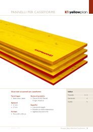
K1 yellowplan is the concrete formwork panel made by Mayr-<br />
Melnhof Kaufmann. The panels are used anywhere where top<br />
quality, durability, and a fl awless concrete appearance is required.<br />
The K1 yellowplan is manufactured in Reuthe in Austria's<br />
Bregenzerwald region and is promptly delivered from there<br />
to your location, or by request directly to the construction<br />
site. The legendary K1 yellowplan has been manufactured<br />
for over 50 years. The new procedure was recognized as a<br />
path breaking achievement from the very beginning. Since<br />
the 80s the K1 yellowplan has been manufactured on an industrial<br />
production line.<br />
18 Mayr-Melnhof Kaufmann<br />
Today this 3-ply laminated formwork panel continues to<br />
impress with its unique quality and high form stability. The<br />
K1 yellowplan formwork panel is made in a jumbo size of<br />
2 x 6 m and thicknesses of 21 and 27 mm and is then cut to<br />
smaller standard sizes.<br />
The enclosed, laminated outer and intermediate layers without<br />
concealed edge bands and showing primarily vertical<br />
growth rings are the foundation for the clean K1 yellowplan<br />
typical concrete appearance.<br />
Version 1 / 2011
Version 1 / 2011<br />
Almost no checks thanks to the narrow<br />
lamella widths used for the edge-glued<br />
outer layers, not even after multiple uses<br />
The special PU-edge seal prevents the<br />
penetration of moisture and the adherence<br />
of concrete sludge on the edge of the panel<br />
The entire surface is fully sanded and<br />
coated with a melamine resin, it provides<br />
an ideal pore structure and guarantees<br />
the unique appearance of the concrete<br />
Due to the continuous intermediate<br />
layers, the longitudinal edges do not<br />
wear out, not even as a result of heavy<br />
mechanical strains<br />
K1 yellowplan<br />
Mayr-Melnhof Kaufmann 19
K1 yellowplan TECHNICAL DATA<br />
Product<br />
Wood species<br />
Wood moisture<br />
Gluing<br />
Weight<br />
Features of panel<br />
Formats<br />
Thicknesses<br />
Surface quality<br />
Edge seal<br />
Packaging<br />
Dimensional tolerances<br />
Design values<br />
20 Mayr-Melnhof Kaufmann<br />
3-ply concrete formwork panel with smooth surface and melamine resin coating<br />
according to Austrian standard ÖN B 3023 «solid wood panels».<br />
Spruce, fi r, mixed types permitted<br />
12 % +/- 3 % at delivery<br />
BFU 100 (AW 100) in accordance with ÖN B 3023<br />
21 mm approx. 10.0 kg / m 2<br />
27 mm approx. 12.5 kg / m 2<br />
• Manufactured as a jumbo size panel, small sizes are cut to exact specifi cations<br />
from jumbo formats<br />
• Locked, glued crosswise<br />
• Fully enclosed, laminated outer and intermediate layer, no concealed edge bands<br />
• Outer layers predominantly showing vertical growth rings, no clamps<br />
• Seamlessly glued intermediate layer, ensures that the longitudinal edges do not tear off<br />
• Seamlessly sanded<br />
• Resistant melamine coating<br />
• Water repellent edge seal<br />
Standard formats (length x width in cm)<br />
100 x 50<br />
150 x 50<br />
200 x 50 / 100<br />
21 and 27 mm<br />
• Seamlessly sanded surface<br />
• Resistant melamine coating with approx. 130 g/m 2 , each side<br />
• Water repellent formwork edge fi nish, yellow • PU edge seal, red<br />
with jumbo- and special sizes with standard formats<br />
(except for 100 x 50 cm)<br />
Packages: 50 pieces of 21 mm or 40 pieces of 27 mm thickness<br />
• Delivered suitable for the construction site, protected<br />
by integrated supporting timber<br />
• Upon request, the packages will be wrapped in plastic foil<br />
• The package units for jumbo formats are subject to arrangement<br />
Thicknesses 21 and 27 mm + / - 1 mm<br />
Widths 50 ≤ 200 cm + / -1 mm<br />
Lengths 100 ≤ 250 cm + / -1 mm<br />
300 ≤ 600 cm + / -2 mm<br />
Longitudinal curvature 100 ≤ 300 cm + / -1 mm<br />
301 ≤ 600 cm + / -1,5 mm<br />
Widths < 50 cm + / -1 ‰<br />
ÖN B 3023<br />
250 x 50 / 100<br />
300 x 50 / 100<br />
Jumbo formats (length x width in cm)<br />
400 x 50 / 100 / 150 / 200<br />
500 x 50 / 100 / 150 / 200<br />
600 x 50 / 100 / 150 / 200<br />
Mechanical properties 21 mm 27 mm Minimal value ÖN B 3023<br />
Bending strength 40 N / mm 2 35 N / mm 2 22 N / mm 2<br />
Modulus of elasticity (mean value) 10.000 N / mm 2 10.000 N / mm 2 10.000 N / mm 2<br />
The calculated values with a wood moisture of 12 %. With heavy moisture penetration up to fiber saturation point,<br />
the values for bending strength and flexural modulus of elasticity may be up to 30 % lower.<br />
Version 1 / 2011
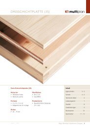
QUALITY<br />
Span L [m]<br />
d = 21 mm 0.40 0.45 0.50 0.55 0.60 0.65 0.70 0.75<br />
5 kN/m² 0.11 0.17 0.26 0.38 0.54 0.75 1.00 1.32<br />
10 kN/m² 0.21 0.34 0.52 0.77 1.08 1.49 2.01 2.65<br />
15 kN/m² 0.32 0.51 0.78 1.15 1.63 2.24 3.01 3.97<br />
20 kN/m² 0.43 0.69 1.05 1.53 2.17 2.99 4.02 5.30<br />
25 kN/m² 0.54 0.86 1.31 1.91 2.71 3.74 5.02 6.62<br />
30 kN/m² 0.64 1.03 1.57 2.30 3.25 4.48 6.03 7.95<br />
35 kN/m² 0.75 1.20 1.83 2.68 3.80 5.23 7.03 9.27<br />
40 kN/m² 0.86 1.37 2.09 3.06 4.34 5.98 8.04 10.59<br />
Load q [kN/m 2 ]<br />
d = 21 mm<br />
E = 10.000 Nmm 2 of K1 yellowplan d = 21 mm<br />
k = 0.646 Deformation factor contingent on number of fi elds for constant load<br />
Span L [m]<br />
d = 27 mm 0.40 0.45 0.50 0.55 0.60 0.65 0.70 0.75<br />
5 kN/m² 0.05 0.08 0.12 0.18 0.26 0.35 0.47 0.62<br />
10 kN/m² 0.10 0.16 0.25 0.36 0.51 0.70 0.95 1.25<br />
15 kN/m² 0.15 0.24 0.37 0.54 0.77 1.05 1.42 1.87<br />
20 kN/m² 0.20 0.32 0.49 0.72 1.02 1.41 1.89 2.49<br />
25 kN/m² 0.25 0.40 0.62 0.90 1.28 1.76 2.36 3.12<br />
30 kN/m² 0.30 0.48 0.74 1.08 1.53 2.11 2.84 3.74<br />
35 kN/m² 0.35 0.57 0.86 1.26 1.79 2.46 3.31 4.36<br />
40 kN/m² 0.40 0.65 0.98 1.44 2.04 2.81 3.78 4.98<br />
Load q [kN/m 2 ]<br />
d = 27 mm<br />
E = 10.000 Nmm 2 of K1 yellowplan d = 27 mm<br />
k = 0.646 Deformation factor contingent on number of fi elds for constant load<br />
Product standard and<br />
quality defi nition<br />
Concrete appearance<br />
Fair-faced concrete<br />
Version 1 / 2011<br />
K1 yellowplan<br />
Defl ection of formwork panel K1 yellowplan d = 21 mm<br />
deflection at midspan [mm]<br />
Defl ection of formwork panel K1 yellowplan d = 27 mm<br />
deflection at midspan [mm]<br />
11<br />
10<br />
9<br />
8<br />
7<br />
6<br />
5<br />
4<br />
3<br />
2<br />
1<br />
0<br />
5<br />
4<br />
3<br />
2<br />
1<br />
0<br />
0,40 0,45 0,50 0,55 0,60 0,65 0,70 0,75<br />
span L [m]<br />
0,40 0,45 0,50 0,55 0,60 0,65 0,70 0,75<br />
span L [m]<br />
40 kN/m²<br />
35 kN/m²<br />
30 kN/m²<br />
25 kN/m²<br />
20 kN/m²<br />
15 kN/m²<br />
10 kN/m²<br />
5 kN/m²<br />
40 kN/m²<br />
35 kN/m²<br />
30 kN/m²<br />
25 kN/m²<br />
20 kN/m²<br />
15 kN/m²<br />
10 kN/m²<br />
5 kN/m²<br />
The product standard for 3-ply concrete formwork panels (ÖN B 3023) refers, for purposes of<br />
classifi cation and test procedures for factory-owned production control, to the relevant<br />
European standards on solid wood panels. In terms of wood quality, the surface refl ects the<br />
appearance class S for solid wood panels (EN 13017-1 Tab.1). The surface structure and<br />
coating is assigned to the smooth GL category according to ÖN B 3023.<br />
Due to the lamella structure of the outer layers, the concrete will reveal a smooth and light<br />
wood grain which becomes more visible with the increase of the panel's service life.<br />
The yellow melamine coating protects the panel and ensures the surface fi nish. It is classifi<br />
ed as lightly absorbent. With time and the number of usages, the absorptive capacity of the<br />
panel surface decreases and the concrete face becomes lighter.<br />
A variety of experience is available in the use of 3-ply melamine coated concrete formwork<br />
panels for fair-faced concrete. Depending on the materials, surface defects in the wood<br />
(knots, resin pockets, nail holes, fi lled knot holes or cracks) will infl uence the absorptive<br />
capacity of the formwork facing and cause dark spots in the concrete when fi rst using panels.<br />
Better results for fair-faced concrete are obtained starting with the 2nd concrete use when<br />
residues on the melamine coating from the formwork facing are removed through alkaline<br />
reaction or neutralized by the concrete.<br />
The recommendations and guidelines in the cement industry must be followed - e.g. leafl et<br />
for fair-faced concrete (version of August 2004) published by DBV and BDZ.<br />
Mayr-Melnhof Kaufmann 21
COMPANY / PRODUCTS / MARKETS<br />
High-quality engineered wood products for<br />
timber and formwork construction<br />
Mayr-Melnhof Kaufmann is one of Europe's leading companies<br />
in the timber industry. At production facilities in four<br />
locations, engineered wood products are manufactured<br />
for construction timber applications. We are a part of the<br />
Mayr-Melnhof Holz Group, which operates four large-scale<br />
sawmills in Austria, Czech Republic, and Russia.<br />
With over 50 years of experience in glulam timber construction,<br />
we are among the pioneers in the industry. Our<br />
product spectrum spans glulam stock beams and custom<br />
shaped laminated structural components, as well as glued<br />
ceiling elements, cross laminated timber, 3-ply panels,<br />
and concrete formwork products.<br />
Mayr-Melnhof Kaufmann Reuthe GmbH -<br />
Pioneer in concrete formwork products<br />
1952 Carpentry business founded by Josef Kaufmann<br />
1962 Production of the fi rst 3-ply concrete formwork<br />
panels<br />
1963 Production of fi rst concrete formwork beams<br />
1985 Industrial production line for K1 yellowplan formwork<br />
panels is launched<br />
2006 Launch of 2nd production line HT 20plus<br />
formwork beam<br />
2007 Sales of HT 20plus passes the 5 Mio meter mark<br />
2008 Acquisition of Stallinger–Kaufmann Group<br />
by Mayr-Melnhof Holz Holding<br />
2008 Company is renamed as Mayr-Melnhof Kaufmann<br />
Reuthe GmbH<br />
2009 Construction of a third production facility for<br />
HT 20plus concrete formwork beams, capacity<br />
expansion to 7.5 Mio meters planned<br />
2010 Expansion of HT 20plus formwork beam product line:<br />
HT 12plus, HT 16plus, HT 24 plus, and HT 30plus<br />
22 Mayr-Melnhof Kaufmann<br />
The product line from Mayr-Melnhof Kaufmann:<br />
L1masterline<br />
Glulam beams<br />
L1vistaline<br />
Duo- / Trio- / Quattro beams<br />
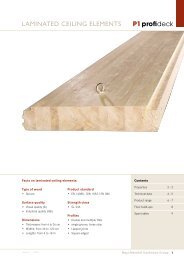
P1profi deck<br />
Laminated seiling elements<br />
P1blocdeck<br />
Floor and wall beams<br />
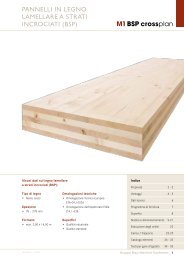
M1 BSP crossplan<br />
Cross-laminated timber<br />
K1 multiplan<br />
3-ply structural panels<br />
K1 yellowplan<br />
Formwork panels<br />
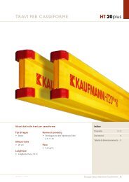
HT 20plus<br />
Formwork beams<br />
Version 1 / 2011
Version 1 / 2011<br />
K1 yellowplan HT 20plus<br />
Mayr-Melnhof Kaufmann formwork technology for construction sites – world-wide!<br />
Algeria<br />
Argentina<br />
Australia<br />
Austria<br />
Azerbaijan<br />
Belgium<br />
Bosnia-Herzegovina<br />
Brazil<br />
Bulgaria<br />
Chile<br />
Croatia<br />
Cyprus<br />
Czech Republic<br />
Estonia<br />
America<br />
Finland<br />
France<br />
Georgia<br />
Germany<br />
Ghana<br />
Greece<br />
Guatemala<br />
Hungary<br />
India<br />
Ireland<br />
Iceland<br />
Italy<br />
Jordan<br />
Kazakhstan<br />
Kuwait<br />
Latvia<br />
Lebanon<br />
Liberia<br />
Libya<br />
Lithuania<br />
Malaysia<br />
Mali<br />
Malta<br />
Marocco<br />
Netherlands<br />
Nigeria<br />
Norway<br />
Oman<br />
Europe<br />
Africa<br />
Peru<br />
Philippines<br />
Poland<br />
Portugal<br />
Qatar<br />
Rumania<br />
Russia<br />
San Marino<br />
Saudi Arabia<br />
Sweden<br />
Switzerland<br />
Serbia<br />
Slovakia<br />
Slovenia<br />
Asia<br />
Spain<br />
South Africa<br />
South Korean<br />
Syria<br />
Tunisia<br />
Turkey<br />
Ukraine<br />
Uruguay<br />
USA<br />
UAE<br />
Australia<br />
Mayr-Melnhof Kaufmann 23
Your distributor:<br />
Mayr-Melnhof Kaufmann Reuthe GmbH<br />
Vorderreuthe 57<br />
6870 Reuthe<br />
Austria<br />
T +43 5574 804 0<br />
F +43 5574 804 202<br />
reuthe@mm-kaufmann.com<br />
www.mm-kaufmann.com