Broch
Broch
Broch

Create successful ePaper yourself
Turn your PDF publications into a flip-book with our unique Google optimized e-Paper software.
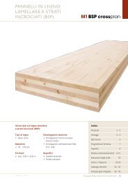
CROSS-LAMINATED TED<br />
TIMBER PANELS<br />
M1 BSP crossplan
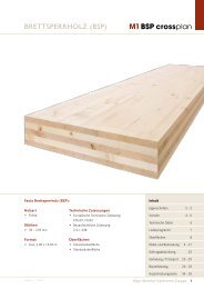
M1 BSP crossplan<br />
State of the art, environmental and fl exible –<br />
developed for use in the timber construction<br />
industry.<br />
M1 BSP crossplan is a solid, static load-bearing and spacecreating<br />
timber panel that is ideal for any structural requirement<br />
thanks to its fl exible dimensions and outstanding<br />
physical properties.<br />
Durable bonding of the cross-wise layered construction<br />
made of high-quality raw material guarantees that the<br />
components are absolutely dimensionally stable and<br />
rigid.<br />
The exceptional structural performance and the environmental<br />
properties of M1 BSP crossplan are assured by<br />
national and international certifi cations.<br />
Numerous areas of use<br />
As a wall, ceiling and roof element<br />
• Family houses and apartment buildings<br />
• Multi-storey buildings<br />
• Public buildings<br />
• Nurseries and schools<br />
• Commercial and offi ce buildings<br />
• Industrial and warehouse buildings<br />
• Modular buildings<br />
• Vacation homes, carports, etc.<br />
Contents<br />
Features 2 - 3<br />
Advantages 4 - 5<br />
Technical data 6<br />
Product range 7<br />
Surface qualities 8<br />
2 Mayr-Melnhof Kaufmann<br />
At a glance<br />
FEATURES<br />
• High-quality, value-maintaining construction<br />
• Space gain due to reduced component thickness<br />
• Flexible design without grid pattern<br />
• Excellent shape and dimensional accuracy<br />
• Outstanding structural properties<br />
• Prefabricated, ready-to-assemble elements<br />
• Short building time due to dry construction<br />
• Recommended for environmentally compatible<br />
architecture<br />
• CO 2 reservoir, reduced carbon foot print<br />
Structural design 9 - 21<br />
Order processing 22<br />
Loading / transport 23 - 25<br />
Construction details 26 - 33<br />
Tender texts 34 - 35<br />
Version 1 / 2011
FEATURES<br />
Weighty arguments take shape<br />
The range of M1 BSP crossplan applications extend from individually<br />
designed detached houses to large-volume building<br />
projects. The large-format solid wood panels make it possible<br />
to cope eff ortlessly with special static challenges.<br />
The clearly structured, layered design principle with simple<br />
jointing details guarantees extremely cost-eff ective use in all<br />
areas of building.<br />
Rapid and straightforward assembly of the elements results<br />
in a signifi cant reduction of building time. The creative fl exibility<br />
meets the needs of modern architecture fans and also<br />
of enthusiasts of traditional building styles.<br />
Version 1 / 2011<br />
M1 BSP crossplan<br />
Facts M1 BSP crossplan:<br />
Types of wood<br />
• Spruce<br />
Thicknesses<br />
• 57 – 278 mm<br />
Formats<br />
• Max. 3,00 x 16,50 m<br />
Technical approvals<br />
• European technical approval<br />
ETA-09 / 0036<br />
• German technical approval<br />
Z-9.1-638<br />
Surface qualities<br />
• Industrial<br />
• Standard<br />
European technical<br />
approval (ETA) ETA -09 / 0036<br />
CE conformity certifi cation<br />
German technical<br />
approval (GCA) Z-9.1-638<br />
PEFC<br />
Chain of Custody<br />
Environmental seal of approval<br />
(IBR Rosenheim)<br />
Component classifi cation EN<br />
13501-2 (HFA)<br />
Mayr-Melnhof Kaufmann 3
M1 BSP crossplan<br />
4 Mayr-Melnhof Kaufmann<br />
ADVANTAGES<br />
Individual scope for architectural design<br />
M1 BSP crossplan provides architects and planners with new<br />
design freedom as there is no need to adhere to any particular<br />
pattern. This high degree of fl exibility in planning allows<br />
for customised solutions to a variety of building tasks.<br />
The use of cross-laminated timber panels creates new attractive<br />
possibilities and forms of expression in the architecture<br />
of modern timber constructions.<br />
High degree of prefabrication<br />
M1 BSP crossplan is cut to size at the factory by our computer-controlled<br />
CNC machining systems on request.<br />
The extremely high degree of prefabrication results in short<br />
assembly times and, hence, to lower building costs.<br />
The ready-to-assemble elements are of a consistently high<br />
product quality and minimise the risk of assembly errors due<br />
to accurately fi tting components.<br />
Solid construction<br />
Solid construction using M1 BSP crossplan not only fulfi ls the<br />
traditional advantages of solid building structures but optimises<br />
them with lower component thicknesses, lower transport<br />
weight, shorter building times and outstanding structural<br />
properties.<br />
The solid, cross-wise layered construction and the innovative<br />
production process are the reason why M1 BSP crossplan<br />
keeps its excellent shape and dimensional stability.<br />
This signifi cantly simplifi es design and building with M1 BSP<br />
crossplan as there is no need to allow for tolerances and<br />
changes in shape.<br />
Version 1 / 2011
ADVANTAGES<br />
Excellent structural properties<br />
Thanks to its outstanding structural properties M1 BSP crossplan<br />
opens up new opportunities in modern timber construction.<br />
The high load-bearing capacity with lower dead weight<br />
allows tight dimensioning of the components even in large<br />
span applications. This results in wall cross-sections well below<br />
any other building materials. Consequently creating more<br />
living space with the same outer dimensions.<br />
The special cross-wise layered construction of M1 BSP crossplan<br />
results in all-round load transfer that makes it ideal for<br />
use as a panel or diaphragm. Point-supported structures or<br />
projections across corners are unproblematic.<br />
What’s more M1 BSP crossplan enables earthquake-proof<br />
construction.<br />
Outstanding environmental life cycle assessment<br />
The raw material for the manufacture of M1 BSP crossplan<br />
mainly originates from domestic forests. For generations,<br />
these forests have been managed and tended according to<br />
the principle of sustainability which means, therefore, our<br />
raw material is not only always available but is also replanted<br />
on a sustainable basis. This is also confi rmed by our 100 %<br />
PEFC certifi cation.<br />
In addition, timber is the only building material that is distinguished<br />
by its positive contribution to the carbon footprint.<br />
For this reason, building with timber constitutes an active<br />
contribution to climate protection.<br />
Recommended for environmentally compatible<br />
architecture<br />
Timber lends a pleasant ambience to rooms and is distinguished<br />
by its visual appeal. It also conveys a sense of cosy<br />
familiarity and warmth.<br />
The perceived surface temperature of M1 BSP crossplan lies<br />
signifi cantly above any other type of building material. Even<br />
at lower room temperatures this leads to a pleasant perception<br />
of temperature.<br />
Version 1 / 2011<br />
M1 BSP crossplan<br />
Mayr-Melnhof Kaufmann 5
M1 BSP crossplan<br />
Product<br />
Lay-up and production<br />
Dimensions<br />
Technical approvals<br />
Types of wood<br />
Lamellas<br />
Strength classes<br />
(lamellas)<br />
Gluing<br />
Density<br />
Moisture content<br />
Dimensional stability<br />
Thermal conductivity<br />
Heat capacity<br />
Water vapour<br />
resistance factor<br />
Airtightness<br />
Sound insulation<br />
Reaction to fi re<br />
Charring rate<br />
Service classes<br />
6 Mayr-Melnhof Kaufmann<br />
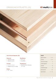
TECHNICAL DATA<br />
M1 BSP crossplan is a large-format, solid timber panel (cross-laminated timber panel) with<br />
multi-layered, crosswise laminated lay-up.<br />
Finger-jointed and planed lamellas are loosely laid next to each other and the fl at surfaces of<br />
the layers glued at right angles to one another.<br />
To avoid uncontrolled stress cracks, the narrow sides are not edge-glued.<br />
The layers are pushed laterally to dimension before applying the pressure (1,2 N/mm 2 ) in<br />
order to obtain a gap-free surface.<br />
Lengths to 16,50 m<br />
Widths to 3,00 m<br />
Thicknesses 57 to 278 mm<br />
European technical approval ETA−09 / 0036<br />
German technical approval Z-9.1-638<br />
Spruce (Picea abies) from domestic forests; other wood species on request<br />
19 to 40 mm, kiln-dried, quality graded and fi nger-jointed<br />
C 24 acc. to EN 338 (equivalent to S 10 acc. to DIN 4074)<br />
A proportion of max. 10 % C 16 is permissible (ETA-09 / 0036)<br />
Melamine resin-based adhesive, Adhesive Type I acc. to EN 301 approved for the gluing of<br />
load-bearing timber components, for both interiors and exteriors, weather-resistant with<br />
transparent glued joint<br />
Approx. 480 kg / m 3<br />
12 % (+ / - 2 %) on delivery<br />
II to panel plane 0,01 % per % change in moisture content<br />
⊥ to panel plane 0,20 % per % change in moisture content<br />
λ = 0,13 W / mK<br />
c = 1,60 kJ / kgK<br />
μ = 60 (at 12 % moisture content)<br />
Airtight from a panel thickness of 95 mm<br />
Dependent on wall or ceiling build-up � see tested sample wall constructions<br />
According EN 13501: D, s2, d0<br />
(standard infl ammability, average smoke emission, no combustible drips)<br />
Fire resistance according to classifi cation report of HFA, EN 13501-2 REI 30 to REI 120<br />
Wall: 0,64 mm/min<br />
Ceiling: 0,71 mm/min<br />
1 or 2 acc. to ETA-03 / 0036<br />
Standard widths 2,40 m / 2,65 m / 2,75 m /<br />
2,90 m / 3,00 m<br />
Version 1 / 2011
PRODUCT RANGE<br />
Product range<br />
Description Layers Panel build-up<br />
Bold = parallel to outer layers<br />
Version 1 / 2011<br />
M1 BSP crossplan<br />
Thickness Standard widths Length Dead weight<br />
M1 BSP crossplan mm mm m m kN / m 2<br />
57* 3s 3 19 19 19 57 0,26<br />
78 3s 3 25 28 25 78<br />
0,38<br />
94 3s 3 33 28 33 94 0,45<br />
95 5s 5 19 19 19 19 19 95 0,46<br />
98 3s 3 32 34 32 98 0,47<br />
106 3s 3 39 28 39 106 0,51<br />
118 3s 3 39 40 39 118 0,57<br />
134 5s 5 27 20 40 20 27 134 0,65<br />
140 5s 5 33 20 34 20 33 140 2,40<br />
0,67<br />
146 5s 5 32 27 28 27 32 146 2,65<br />
0,70<br />
160 5s 5 40 20 40 20 40 160<br />
2,75<br />
2,90<br />
max. 16,50<br />
0,77<br />
173 5s 5 40 27 39 27 40 173 3,00<br />
0,83<br />
184 5s 5 39 33 40 33 39 184 0,89<br />
198 5s 5 39 40 40 40 39 198 0,95<br />
214 7s 7 39 19 39 20 39 19 39 214 1,03<br />
214 7ss 7 39 39 19 20 19 39 39 214 1,03<br />
240 7s 7 39 27 40 28 40 27 39 240 1,16<br />
240 7ss 7 39 40 40 28 40 40 39 240 1,16<br />
258 7ss 7 39 40 33 28 27 27 39 258 1,24<br />
278 7ss 7 39 40 40 40 40 40 39 278 1,34<br />
ss: outer layers consist of 2 parallel top layers.<br />
Further dimensions (e.g. optimised for 2-axis load transfer) possible on request.<br />
The orientation of the top layer, lengthwise (DL) or transverse (DQ), can be selected according to the application.<br />
* available in pairs only, on request<br />
Mayr-Melnhof Kaufmann 7
M1 BSP crossplan<br />
Industrial quality Standard quality<br />
Surface qualities<br />
Industrial quality<br />
Standard quality<br />
Note<br />
8 Mayr-Melnhof Kaufmann<br />
M1 BSP crossplan is supplied in two surface qualities.<br />
SURFACE QUALITIES<br />
For non-visual applications in compliance with all structural requirements, for subsequent<br />
installation (e.g. plasterboard).<br />
• The top lamellas are exclusively sorted according to the sorting criteria of the loadbearing<br />
strength C24 in line with EN 338. A proportion of max. 10 % C 16 is permissible<br />
(ETA-09 / 0036).<br />
• Colour variations of individual lamella (e.g. blue stain) as well as loose knots, bark<br />
ingrowths and resin pockets are permitted.<br />
• Isolated gaps in the outer layers, glue stains as well as isolated pressure points and<br />
markings can appear<br />
• Planed surface only<br />
With additional requirements for a visual application.<br />
• Stringent visual criteria for outer layers are applied in addition to the sorting criteria for<br />
load-bearing strength.<br />
• Selected outer lamellas with healthy intergrown knots. A few isolated loose knots are possible,<br />
defects and small resin pockets are permissible.<br />
• Planed and sanded surface.<br />
Timber is a natural product. Variations in the surface quality can occur with even the most<br />
careful selection of the raw material.<br />
The appearance of the M1 BSP crossplan surface is determined by the board structure of<br />
the top layer. Gaps may occur between the individual boards over time due to shrinkage, etc.<br />
Drying checks are also possible.<br />
Version 1 / 2011
STRUCTURAL DESIGN<br />
General<br />
Building practice approximation<br />
method<br />
for calculation of<br />
cutting forces and<br />
deformations.<br />
Version 1 / 2011<br />
M1 BSP crossplan<br />
Components made of M1 BSP crossplan are designed and executed according to the following<br />
standards:<br />
• Design according to DIN 1052:2008 allowing for German technical approval<br />
(Z-9.1-638)<br />
or<br />
• Design according to EN 1995 (Eurocode 5) allowing for Appendices 2 to 4 of European<br />
technical approval ETA-09 / 0036<br />
The structural analysis for M1 BSP crossplan must be conducted in each individual case and<br />
the standards and regulations applicable at the site of use must be complied with.<br />
Analysis of the stress distribution and internal forces and moments must be conducted according<br />
to the composite theory allowing for shear deformations.<br />
An approximation method is required in practical use. Here, the calculation is carried out as<br />
for a beam under bending moment with fl exible joining means (Austrian standard B 4100 / 2;<br />
DIN 1052; EN 1995-1-1, Appendix B), but the shear deformation of the transverse layers is<br />
taken into consideration instead of the fl exibility of the joining means.<br />
Using this approach, it is possible to achieve a good approximation for the stress and deformation<br />
calculations.<br />
At the same time, for the actual design the moments of inertia are multiplied by a reduction<br />
factor - which takes into account the net moments of inertia and the rolling shear deformation<br />
of the transverse layers.<br />
Using the eff ective moments of inertia (Ieff ) obtained as a result, it is possible to calculate<br />
the cutting forces and deformations as for beams under bending moment with a rigid bond.<br />
M Q<br />
Lamellas stressed in the direction of the fibres<br />
� High stiffness<br />
Cross-section<br />
Q<br />
Tension<br />
Lamellas stressed transverse to the direction of the fibres<br />
� No stiffness E = 0<br />
M<br />
σ = 0<br />
Normal stress due to bending<br />
Pressure<br />
σ = 0<br />
Shear stress<br />
Rolling shear transversally<br />
Rolling shear transversally<br />
Note:<br />
The solution only applies exactly for single span beams with sinusoidal uniform load. It should<br />
also be noted that the eff ective moments of inertia Ieff depend on the width between supports<br />
of the panels. The shorter the width between supports, the greater the proportion of<br />
shear deformation and thus also the percentage reduction of the moments of inertia (compare<br />
table of cross-sectional values). Beyond this, a more accurate calculation method is<br />
necessary particularly in the case of point loads and very short beam lengths.<br />
In the case of continuous beams, the width between supports of the fi eld concerned should<br />
be used for the width between supports for selection of the eff ective moment of inertia 4 / 5<br />
Ieff , in the case of cantilever beams double the protruding length should be used (cf. EN<br />
1995-1-1, Appendix B). However, calculation of the cutting force and deformation must be<br />
performed using the actual widths between supports or protruding lengths.<br />
This approximation method is also the basis of the design charts.<br />
Mayr-Melnhof Kaufmann 9
M1 BSP crossplan<br />
Design as panel acc.<br />
to DIN 1052:2008<br />
(Z-9.1-638)<br />
Design as a slab acc.<br />
to DIN 1052:2008<br />
(Z-9.1-638)<br />
Wall slab<br />
Lintel design<br />
Wall slab as column<br />
Vibration design<br />
Fire resistant design<br />
10 Mayr-Melnhof Kaufmann<br />
STRUCTURAL DESIGN<br />
The stress perpendicular to the panel plane is applicable for the design. Analysis of the stress<br />
distribution and internal forces and moments must be conducted according to the German<br />
technical approval (Z-9.1-638) in line with the composite theory referred to above allowing<br />
for shear deformations (DIN 1052:2008, Appendix D).<br />
The various bending stiff nesses of the relevant clamping directions must be allowed for in the<br />
panel stress. That is to say, that in the longitudinal direction of the panel (main load-bearing<br />
direction) the lamella layers may be taken into consideration in the panel’s longitudinal direction<br />
and in the transverse direction of the panel the lamella layers may be taken into consideration<br />
in the panel’s transverse direction.<br />
If the panel lay-up transverse to the direction of span corresponds to the lay-up of a 3-layer<br />
panel, then the cross-sectional values must thus be taken from the table (page 11).<br />
Note:<br />
In the case of 3-layer panels, when designing transverse to the main load-bearing direction,<br />
the middle layer must be calculated as a solid timber cross-section.<br />
In the case of stress in the panel plane, only those layers where the fi bre direction runs<br />
parallel to the force components considered may be taken into account (German technical<br />
approval Z-9.1-638).<br />
The following models must be diff erentiated when designing in the panel plane.<br />
In the case of stress as a wall slab (bracing ceilings and walls), it is necessary to conduct<br />
the corresponding shear stress analyses in accordance with the German technical approval.<br />
Only the lamella layers running parallel to the direction of force or direction of internal forces<br />
and moments are taken into account for the design. The height of the individual beam crosssections<br />
must be specifi ed in a particular case. Thus wall slabs may also be calculated allowing<br />
for door and window openings.<br />
Only the lamella layers running parallel to the direction of force are taken into account for<br />
the design of the load carrying capacity in the panel plane. The buckling analysis required<br />
for this must be conducted according to the equivalent member method in accordance with<br />
DIN 1052 or EN 1995. The corresponding slendernesses (λ) and the associated reduction<br />
factors (κ) must be determined in the process.<br />
It must be ensured that impacts on components or supporting structures that are to be<br />
anticipated frequently do not give rise to any vibrations which could impair the structure’s<br />
function or lead to unease. The required analysis must be conducted in accordance with<br />
EN 1995-1-1 whereby a special investigation must be carried out for apartment ceilings with<br />
a resonant frequency not exceeding 8 Hz.<br />
Note:<br />
When conducting an analysis in accordance with DIN 1052, the defl ection on the ideal single<br />
span beam must be determined from the continuous and quasi-continuous load. With a<br />
defl ection of more than 6 mm, a separate analysis must also be performed.<br />
The fi re resistant design of M1 BSP crossplan is carried out in accordance with EN 1995 or<br />
DIN 1052 / 4102 (referred to as thermal design with inclusion of the residual load-bearing<br />
capacity). Charring rate: See technical data on page 6<br />
Version 1 / 2011
STRUCTURAL DESIGN<br />
Material characteristics<br />
(acc. to Z-9.1-638)<br />
Calculation value I eff<br />
Version 1 / 2011<br />
M1 BSP crossplan<br />
Description Lay-up A voll A netto I voll I eff (dependent on span between supports of single span beam)<br />
M1 BSP crossplan<br />
Thicknesses<br />
Layers<br />
Bold = parallel to<br />
fi bre direction of<br />
outer layers<br />
Property Numerical value<br />
Strength classes of lamellas C24<br />
Modulus of elasticity parallel<br />
• For the lamella layers parallel in load-bearing direction<br />
E II 1 1000,00 [N / mm2 ]<br />
Modulus of elasticity perpendicular E L 370,00 [N / mm2 ]<br />
Modulus of shear<br />
• As a result of rolling shear stress<br />
G R 50,00 [N / mm2 ]<br />
Rolling shear<br />
• Rolling shear stress of the crosswise layers<br />
(bxd 3 ) /<br />
12<br />
1,00 m 2,00 m 2,50 m 3,00 m 4,00 m 6,00 m 8,00 m<br />
I eff I eff /I Voll I eff I eff /I Voll I eff I eff /I Voll I eff I eff /I Voll I eff I eff /I Voll I eff I eff /I Voll I eff I eff /I Voll<br />
[mm] [ ] [mm] [cm²] [cm²] [cm 4 ] [cm 4 ] [%] [cm 4 ] [%] [cm 4 ] [%] [cm 4 ] [%] [cm 4 ] [%] [cm 4 ] [%] [cm 4 ] [%]<br />
57 3s 19 19 19 570 380 1468 1085 70 1358 88 1401 91 1426 92 1452 94 1471 95 1477 96<br />
78 3s 25 28 25 780 500 3955 2255 57 3211 81 3391 86 3498 88 3612 91 3699 94 3730 94<br />
94 3s 33 28 33 940 660 6922 3664 53 5508 80 5889 85 6123 88 6376 92 6572 95 6644 96<br />
95 5s 19 19 19 19 19 950 570 7145 3248 45 4760 67 5047 71 5219 73 5402 76 5542 78 5592 78<br />
98 3s 32 34 32 980 640 7843 3741 48 5927 76 6408 82 6707 86 7037 90 7294 93 7389 94<br />
106 3s 39 28 39 1060 780 9925 4994 50 7741 78 8347 84 8723 88 9138 92 9463 95 9583 97<br />
118 3s 39 40 39 1180 780 13692 5507 40 9539 70 10564 77 11231 82 11994 88 12612 92 12845 94<br />
134 5s 27 20 40 20 27 1340 940 20051 7772 39 12668 63 13765 69 14451 72 15209 76 15804 79 16025 80<br />
140 5s 33 20 34 20 33 1400 1000 22867 8449 37 14637 64 16139 71 17101 75 18187 80 19056 83 19382 85<br />
146 5s 32 27 28 27 32 1460 920 25934 7959 31 14884 57 16722 64 17936 69 19340 75 20493 79 20931 81<br />
160 5s 40 20 40 20 40 1600 1200 34133 11770 34 21354 63 23872 70 25530 75 27441 80 29006 85 29599 87<br />
173 5s 39 28 39 28 39 1730 1170 43148 11870 28 23466 54 26867 62 29196 68 31978 74 34334 80 35246 82<br />
184 5s 39 33 40 33 39 1840 1180 51913 25658 49 29853 58 32807 63 36425 70 39567 76 40805 79<br />
198 5s 39 40 40 40 39 1980 1180 64687 28216 44 33493 52 37340 58 42207 65 46580 72 48342 75<br />
214 7s 39 19 39 20 39 19 39 2140 1560 81670 54885 67 58399 72 62400 76 65632 80 66848 82<br />
214 7ss 39 39 19 20 19 39 39 2140 1760 81670 54727 67 60359 74 67488 83 73897 90 76478 94<br />
240 7s 39 27 40 28 40 27 39 2400 1580 115200 73025 63 79582 69 85078 74 87195 76<br />
240 7ss 39 40 40 28 40 40 39 2400 1860 115200 76001 66 87804 76 99117 86 103879 90<br />
258 7ss 39 40 33 28 27 27 39 2580 1920 143113 102032 71 117910 82 124844 87<br />
278 7ss 39 40 40 40 40 40 39 2780 1980 179041 118227 66 140134 78 150028 84<br />
All details relate to a 1 m wide panel strip<br />
Avoll total of cross-section<br />
Anetto cross-sectional value for the verifi cation of the compressive strength in the direction of<br />
orientation of the top layer<br />
Ivoll moment of inertia of the full section – as a reference value<br />
Ieff eff ective moment of inertia of the full section – as reference value only<br />
Ieff / Ivoll ratio that specifi es to what extent the cross-wise layers alter the cross-section’s<br />
eff ective moment of inertia<br />
zul τ R<br />
0,45 [N / mm 2 ]<br />
Bending strength zul σ B 10,00 [N / mm2 ]<br />
Tension parallel<br />
• For the lamella layers parallel in load-bearing direction<br />
zul σ Z, II 7,00 [N / mm2 ]<br />
Tension perpendicular zul σ Z, ⊥ 0,05 [N / mm2 ]<br />
Compressive strength parallel<br />
• For the lamella layers in the direction of the grain<br />
zul σ D, II 8,50 [N / mm2 ]<br />
Compressive strength perpendicular<br />
• An increase by 20% is permitted in the case of unobjectionable indentations<br />
zul σ D, ⊥<br />
2,00 [N / mm 2 ]<br />
Mayr-Melnhof Kaufmann 11
M1 BSP crossplan<br />
Design according to<br />
ETA-09 / 0036<br />
General<br />
The following applies for<br />
a 5-layer symmetrical<br />
lay-up:<br />
Flexibility factors γ<br />
12 Mayr-Melnhof Kaufmann<br />
STRUCTURAL DESIGN<br />
Design of the cross-laminated timber may be carried out according to EN 1995-1-1 and EN<br />
1995-1-2 allowing for Appendices 2 to 4 of the European technical approval. Only lamellas<br />
which are arranged in the direction of the mechanical stress may be taken into consideration<br />
for calculation of the characteristic cross-sectional values. Reference must be made to the<br />
characteristic strength and stiff ness of the solid timber according to to Appendix 3 (of European<br />
Technical Approval 09-0036) for designing the components made of cross-laminated timber<br />
in accordance with E 1995-1-1. Diff erent stiff nesses must be taken into consideration in both<br />
main directions for cross-laminated timber with multi-axial spaning in both main directions.<br />
Panel stress of the cross-laminated timber<br />
The eff ective bending stiff ness depends on the eff ective moment of inertia Ieff . Calculation of<br />
the eff ective moment of inertia and therefore of the eff ective bending stiff ness time is carried<br />
out acc. to E 1995-1-1 (Section 9.1.3 and Appendix B):<br />
� Distances between centres of gravity:<br />
with<br />
and<br />
for symmetrical lay-up<br />
The fl exibility factors γ allow for the shear deformation (rolling shear) of the cross-wise layers,<br />
the expression of EN 1995-1-1 should be replaced by<br />
� The fl exibilities thus arise from:<br />
� where:<br />
E 1,3 = 11600 N / mm² modulus of elasticity for C24<br />
G 9090 = 50 N / mm² modulus of shear for C24<br />
l = decisive width between supports<br />
where<br />
where<br />
t tot<br />
individual moment of inertia of longitudinal layers i = 1 to 3<br />
areas of the longitudinal layers<br />
t 1<br />
t 2<br />
t 3<br />
b<br />
t 1<br />
t 2<br />
Version 1 / 2011
STRUCTURAL DESIGN<br />
Slab stress of the<br />
cross-laminated timber<br />
Panel load<br />
Version 1 / 2011<br />
M1 BSP crossplan<br />
The following equations may be used for stress in the panel plane (slab stress) under the<br />
requirements of the technical column theory:<br />
Thickness of the lamella layers in the direction of stress<br />
Thickness of the lamella layers normal to the direction of stress<br />
� Distances between centres of gravity:<br />
Maximum<br />
where<br />
Design value of the shear force<br />
Calculation of the bending stresses and bending stiff ness may be carried out using the full<br />
section of the lamella layers in the direction of stress. When calculating the shear stresses,<br />
the net area with the smaller cross-section of the two stress directions is decisive.<br />
Material characteristics according to ETA-09 / 0036<br />
Property Numerical value<br />
Strength classes of lamellas<br />
Modulus of elasticity:<br />
C24<br />
• Parallel to fi bre direction of lamellas E0, mean<br />
11600,00 N / mm<br />
• Perpendicular to fi bre direction E90, mean<br />
2<br />
370,00 N / mm2 Modulus of shear:<br />
• Parallel to fi bre direction of lamellas G 090, mean<br />
• Perpendicular to the fi bre direction of the lamellas, modulus of rolling<br />
shear G 9090, mean<br />
Bending strength:<br />
• Parallel to fi bre direction of lamellas f m, k<br />
• f m, k may be increased to to 28,8 N/mm 2 for C 24 (f m, CLT, k) in accordance with the<br />
approval referred to above<br />
Tensile strength:<br />
• Perpendicular to the fi bre direction of the lamellas f t, 90, k<br />
Compressive strength:<br />
• Perpendicular to the fi bre direction of the lamellas f c, 90, k<br />
Shear strength:<br />
• Parallel to fi bre direction of lamellas f v, 090, k<br />
• Perpendicular to the fi bre direction of the lamellas (rolling shear strength) f v, 9090, k<br />
t1 t2 t1 t2 t3 650,00 N / mm 2<br />
50,00 N / mm 2<br />
24,00 N / mm 2<br />
0,12 N / mm 2<br />
2,50 N / mm 2<br />
2,50 N / mm 2<br />
1,10 N / mm 2<br />
Mayr-Melnhof Kaufmann 13<br />
H
M1 BSP crossplan<br />
Slab load<br />
Connecting means<br />
according to<br />
ETA-09 / 0036<br />
14 Mayr-Melnhof Kaufmann<br />
STRUCTURAL DESIGN<br />
Property Numerical value<br />
Strength classes of lamellas<br />
Modulus of elasticity:<br />
C24<br />
• Parallel to fi bre direction of lamellas E0, mean<br />
11600,00 N / mm2 Modulus of shear:<br />
• Parallel to fi bre direction of lamellas G 090, mean<br />
Bending strength:<br />
• Parallel to fi bre direction of lamellas f m, k<br />
Tensile strength:<br />
• Parallel to fi bre direction of lamellas f t, 90, k<br />
Compressive strength:<br />
• Parallel to fi bre direction of lamellas f c, 90, k<br />
Shear strength:<br />
• Parallel to fi bre direction of lamellas f v, 090, k<br />
250,00 N / mm 2<br />
24,00 N / mm 2<br />
14,00 N / mm 2<br />
21,00 N / mm 2<br />
5,00 N / mm 2<br />
The load-carrying connection of M1BSP crossplan elements must be carried out separately<br />
and using suitable joining means for each building task. The design of the connecting means<br />
(diameter, number und distances) should be within the responsibility of a specialist familiar<br />
with cross-laminated timber.<br />
As a recommendation for determining the design values, reference is made to «Bemessungsvorschläge<br />
für Verbindungsmittel in Brettsperrholz» [Design Suggestions for Joining Means<br />
in Cross-laminated Timber] [from Bauen mit Holz [Building with Timber] 111 (2009), BLASS<br />
Hans Joachim, UIBEL Thomas] and to Expert Opinion no. GU07-4-2-1-01 and GU11-402-1 of<br />
the Technical University of Graz. Specifi ed here are the embedment strengths for screwed<br />
and nailed joints, dowel pins, fi t bolts and bolts, in addition to a design suggestion for axial<br />
stress (tension).<br />
A distinction should be made between joints in the narrow surfaces and those in the lateral<br />
surface when referring to joints. The static analyses of the joints must be conducted in<br />
accordance with EN 13501 -1-1.<br />
Version 1 / 2011
STRUCTURAL DESIGN<br />
Minimum distances<br />
between connecting<br />
means in the lateral<br />
surfaces<br />
Minimum distances<br />
between connecting<br />
means in the narrow<br />
surfaces<br />
F<br />
a1, c<br />
a2, c<br />
t i<br />
t M1 BSP<br />
a1<br />
a2, c<br />
a1, t<br />
Sample calculations<br />
Version 1 / 2011<br />
F<br />
F<br />
M1 BSP crossplan<br />
a1,t a1,c a1 a2,t a2,c a2 Screws1) 6 × d 6 × d 4 × d 6 × d 2,5 × d 2,5 × d<br />
Nails (7+3 × cosα) × d 6 × d (3+3 × cosα) × d (3+4 × sinα) × d 3 × d 3 × d<br />
Dowel pins<br />
5 × d 4 × d × sinα (3+3 × cosα) × d 3 × d 3 × d 3 × d<br />
Fit bolts<br />
(min. 3 × d)<br />
Bolts<br />
Screws 1)<br />
α<br />
a1, t<br />
a2<br />
a2<br />
5 × d 6 × d (3+3 × cosα) × d<br />
(min. 4 × d)<br />
Minimum thickness<br />
of decisive lamella layer<br />
t 1 in mm<br />
d > 8 mm : 3 × d<br />
d ≤ 8 mm : 2 × d<br />
Minimum thickness<br />
of cross-laminated timber<br />
t BSP in mm<br />
3 × d 3 × d 4 × d<br />
a 1,t a 1,c a 1 a 2,t a 2<br />
Screws1) 12 × d 7 × d 10 × d 5 × d 3 × d<br />
Dowel pins<br />
Fit bolts<br />
5 × d 3 × d 4 × d 3 × d 3 × d<br />
Bolts 5 × d 4 × d 4 × d 3 × d 4 × d<br />
Minimum anchoring depth<br />
of joining means in narrow<br />
surfaces t 1 or t 2 in mm<br />
10 × d 10 × d<br />
Dowel pins<br />
Fit bolts<br />
d 6 × d 5 × d<br />
Bolts d 6 × d 5 × d<br />
α Angle between force and fi bre direction of top layers<br />
1) Self-tapping wood screws<br />
t 1 Minimum anchoring depth of the joining means in the narrow surfaces of the lateral timber<br />
or lateral timber thickness<br />
t 2 Minimum anchoring depth of the joining means in the narrow surfaces of the central timber<br />
a1, c<br />
α<br />
To make the calculation method of ETA 09-0036 clear, calculation examples with explanatory<br />
demonstration of proof according to EN 1995-1-1 may be found in the download area at<br />
www.mm-kaufmann.com.<br />
F<br />
a1<br />
F<br />
a2<br />
a2, c<br />
a2, t<br />
α<br />
F<br />
Mayr-Melnhof Kaufmann 15<br />
F
M1 BSP crossplan<br />
General<br />
Structural system<br />
Single span beam<br />
Determination of the<br />
permissible load q<br />
for the required width<br />
between supports<br />
Maximum defl ection:<br />
L / 400<br />
Direction of span parallel to<br />
fi bre direction of top layer<br />
perm. load q k [kN / m²]<br />
perm. load q k [kN / m²]<br />
16 Mayr-Melnhof Kaufmann<br />
q = g 2 + p [kN / m 2 ]<br />
g 1 = dead weight of the panel; allowed for in the diagram<br />
g 2 = ceiling build-up<br />
p = live load<br />
Single span beam under uniform load q k ; max f = L / 400<br />
Width between supports L [m]<br />
Width between supports L [m]<br />
DESIGN CHARTS<br />
The tables referred to serve for the preliminary design and do not replace a structural calculation.<br />
p<br />
g = g 1 + g 2<br />
10,0<br />
9,0<br />
8,0<br />
7,0<br />
6,0<br />
5,0<br />
4,0<br />
3,0<br />
2,0<br />
1,0<br />
0,0<br />
10,0<br />
9,0<br />
8,0<br />
7,0<br />
6,0<br />
5,0<br />
4,0<br />
3,0<br />
2,0<br />
1,0<br />
0,0<br />
2,0<br />
4,0<br />
2,5<br />
L<br />
3,0<br />
3,5<br />
4,0<br />
4,5<br />
max 3,00 m<br />
5,0<br />
5,5<br />
6,0<br />
max 16,50 m<br />
78 3S DL 98 3S DL 118 3S DL 134 5S DL 140 5S DL 146 5S DL 160 5S DL 173 5S DL<br />
184 5S DL 198 5S DL 214 7S DL 214 7SS DL 240 7S DL 240 7SS DL 258 7SS DL 278 7SS DL<br />
4,5<br />
5,0<br />
5,5<br />
6,0<br />
6,5<br />
7,0<br />
7,5<br />
8,0<br />
6,5<br />
8,5<br />
7,0<br />
9,0<br />
7,5<br />
9,5<br />
Version 1 / 2011<br />
8,0<br />
10,0
DESIGN CHARTS<br />
General<br />
Structural system<br />
Single span beam<br />
Determination of the<br />
permissible load q<br />
for the required width<br />
between supports<br />
Maximum defl ection:<br />
L / 300<br />
Direction of span parallel to<br />
fi bre direction of top layer<br />
Version 1 / 2011<br />
perm. load q k [kN / m²]<br />
perm. load q k [kN / m²]<br />
q = g 2 + p [kN / m 2 ]<br />
g 1 = dead weight of the panel; allowed for in the diagram<br />
g 2 = ceiling buid-up<br />
p = live load<br />
Single span beam under uniform load q k ; max f = L / 300<br />
M1 BSP crossplan<br />
The tables referred to serve for the preliminary design and do not replace a structural calculation.<br />
p<br />
g = g 1 + g 2<br />
10,0<br />
9,0<br />
8,0<br />
7,0<br />
6,0<br />
5,0<br />
4,0<br />
3,0<br />
2,0<br />
1,0<br />
0,0<br />
10,0<br />
9,0<br />
8,0<br />
7,0<br />
6,0<br />
5,0<br />
4,0<br />
3,0<br />
2,0<br />
1,0<br />
0,0<br />
2,0<br />
4,0<br />
2,5<br />
L<br />
3,0<br />
3,5<br />
4,0<br />
4,5<br />
max 3,00 m<br />
5,0<br />
5,5<br />
6,0<br />
max 16,50 m<br />
78 3S DL 98 3S DL 118 3S DL 134 5S DL 140 5S DL 146 5S DL 160 5S DL 173 5S DL<br />
4,5<br />
5,0<br />
5,5<br />
6,0<br />
Width between supports L [m]<br />
184 5S DL 198 5S DL 214 7S DL 214 7SS DL 240 7S DL 240 7SS DL 258 7SS DL 278 7SS DL<br />
6,5<br />
7,0<br />
7,5<br />
Width between supports L [m]<br />
8,0<br />
6,5<br />
8,5<br />
7,0<br />
9,0<br />
7,5<br />
9,5<br />
Mayr-Melnhof Kaufmann 17<br />
8,0<br />
10,0
M1 BSP crossplan<br />
General<br />
Structural system<br />
Double span beam<br />
Determination of the<br />
permissible load q<br />
for the required width<br />
between supports<br />
Maximum defl ection:<br />
L / 400<br />
Direction of span parallel to<br />
fi bre direction of top layer<br />
perm. load q k [kN / m²]<br />
perm. load q k [kN / m²]<br />
18 Mayr-Melnhof Kaufmann<br />
Double span beam under uniform load q k ; max f = L / 400<br />
10,0<br />
9,0<br />
8,0<br />
7,0<br />
6,0<br />
5,0<br />
4,0<br />
3,0<br />
2,0<br />
1,0<br />
0,0<br />
20,0<br />
19,0<br />
18,0<br />
17,0<br />
16,0<br />
15,0<br />
14,0<br />
13,0<br />
12,0<br />
11,0<br />
10,0<br />
9,0<br />
8,0<br />
7,0<br />
6,0<br />
5,0<br />
4,0<br />
3,0<br />
2,0<br />
2,5<br />
3,0<br />
3,5<br />
4,0<br />
4,5<br />
max 3,00 m<br />
5,0<br />
DESIGN CHARTS<br />
The tables referred to serve for the preliminary design and do not replace a structural calculation.<br />
p<br />
g = g 1 + g 2<br />
4,0<br />
L L<br />
q = g 2 + p [kN / m 2 ]<br />
g 1 = dead weight of the panel; allowed for in the diagram<br />
g 2 = live load, under worst case conditions<br />
p < 2q / 3<br />
4,5<br />
5,0<br />
5,5<br />
6,0<br />
5,5<br />
6,5<br />
6,0<br />
max 16,50 m<br />
78 3S DL 98 3S DL 118 3S DL 134 5S DL 140 5S DL 146 5S DL 160 5S DL 173 5S DL<br />
Width between supports L [m]<br />
184 5S DL 198 5S DL 214 7S DL 214 7SS DL 240 7S DL 240 7SS DL 258 7SS DL 278 7SS DL<br />
Width between supports L [m]<br />
6,5<br />
7,0<br />
7,0<br />
7,5<br />
7,5<br />
8,0<br />
8,0<br />
Version 1 / 2011
DESIGN CHARTS<br />
General<br />
Structural system<br />
Double span beam<br />
Determination of the<br />
permissible load q<br />
for the required width<br />
between supports<br />
Maximum defl ection:<br />
L / 300<br />
Direction of span parallel to<br />
fi bre direction of top layer<br />
Version 1 / 2011<br />
perm. load q k [kN / m²]<br />
perm. load q k [kN / m²]<br />
Double span beam under uniform load q k ; max f = L / 300<br />
12,0<br />
11,0<br />
10,0<br />
9,0<br />
8,0<br />
7,0<br />
6,0<br />
5,0<br />
4,0<br />
3,0<br />
2,0<br />
1,0<br />
0,0<br />
29,0<br />
27,0<br />
25,0<br />
23,0<br />
21,0<br />
19,0<br />
17,0<br />
15,0<br />
13,0<br />
11,0<br />
9,0<br />
7,0<br />
5,0<br />
2,0<br />
2,5<br />
3,0<br />
3,5<br />
4,0<br />
4,5<br />
M1 BSP crossplan<br />
The tables referred to serve for the preliminary design and do not replace a structural calculation.<br />
p<br />
g = g 1 + g 2<br />
4,0<br />
L L<br />
q = g 2 + p [kN / m 2 ]<br />
g 1 = dead weight of the panel; allowed for in the diagram<br />
g 2 = live load, under worst case conditions<br />
p < 2q / 3<br />
4,5<br />
5,0<br />
5,5<br />
max 3,00 m<br />
5,0<br />
6,0<br />
5,5<br />
6,5<br />
6,0<br />
max 16,50 m<br />
78 3S DL 98 3S DL 118 3S DL 134 5S DL 140 5S DL 146 5S DL 160 5S DL 173 5S DL<br />
Width between supports L [m]<br />
184 5S DL 198 5S DL 214 7S DL 214 7SS DL 240 7S DL 240 7SS DL 258 7SS DL 278 7SS DL<br />
Width between supports L [m]<br />
6,5<br />
7,0<br />
7,0<br />
7,5<br />
7,5<br />
8,0<br />
Mayr-Melnhof Kaufmann 19<br />
8,0
M1 BSP crossplan<br />
General<br />
Structural system<br />
Triple span beam<br />
Determination of the<br />
permissible load q<br />
for the required width<br />
between supports<br />
Maximum defl ection:<br />
L / 400<br />
Direction of span parallel to<br />
fi bre direction of top layer<br />
perm. load q k [kN / m²]<br />
p<br />
g = g + g 1 2<br />
20 Mayr-Melnhof Kaufmann<br />
q = g 2 + p [kN / m 2 ]<br />
g 1 = dead weight of the panel; allowed for in the diagram<br />
g 2 = ceiling build-up<br />
p = live load, under worst case conditions<br />
p < 2q / 3<br />
Triple span beam under uniform load q k ; max f = L / 400<br />
15,0<br />
14,0<br />
13,0<br />
12,0<br />
11,0<br />
10,0<br />
9,0<br />
8,0<br />
7,0<br />
6,0<br />
5,0<br />
4,0<br />
3,0<br />
2,0<br />
1,0<br />
0,0<br />
35,0<br />
33,0<br />
31,0<br />
29,0<br />
27,0<br />
25,0<br />
23,0<br />
21,0<br />
19,0<br />
17,0<br />
15,0<br />
13,0<br />
11,0<br />
9,0<br />
7,0<br />
5,0<br />
2,0<br />
2,5<br />
3,0<br />
3,5<br />
max 3,00 m<br />
DESIGN CHARTS<br />
The tables referred to serve for the preliminary design and do not replace a structural calculation.<br />
3,5<br />
4,0<br />
max 16,50 m<br />
78 3S DL 98 3S DL 118 3S DL 134 5S DL 140 5S DL 146 5S DL 160 5S DL 173 5S DL<br />
184 5S DL 198 5S DL 214 7S DL 214 7SS DL 240 7S DL 240 7SS DL 258 7SS DL 278 7SS DL<br />
4,0<br />
4,5<br />
Width between supports L [m]<br />
4,5<br />
5,0<br />
5,0<br />
5,5<br />
5,5<br />
Version 1 / 2011
DESIGN CHARTS<br />
General<br />
Vertical load on wall<br />
Structural system:<br />
M1 BSP crossplan wall<br />
under vertical load;<br />
R30 / one-sided<br />
Version 1 / 2011<br />
perm. load N k [kN / m]<br />
900,0<br />
800,0<br />
700,0<br />
600,0<br />
500,0<br />
400,0<br />
300,0<br />
200,0<br />
100,0<br />
0,00<br />
1,00 m<br />
2,00 m<br />
M1 BSP crossplan<br />
The tables referred to serve for the preliminary design and do not replace a structural calculation.<br />
• Determination of the permissible vertical load N in relation to 1,0 m wall width.<br />
• Wall pillars must be considered separately<br />
• Load assumptions - wind load: 1,0 kN / m²<br />
• Classifi cation REI 30 / one-sided<br />
• EI according to classifi cations<br />
h<br />
w k = 1,0 kN/m<br />
zul N k<br />
Top layer in vertical direction<br />
max 3,00 m<br />
max 16,50 m<br />
95 5S DQ 98 3S DQ 118 3S DQ 134 5S DQ 146 5S DQ 160 5S DQ<br />
Wall height<br />
2,50 m<br />
3,00 m<br />
Mayr-Melnhof Kaufmann 21
M1 BSP crossplan<br />
Enquiry<br />
Preparation of quote<br />
Order confi rmation<br />
and production release<br />
22 Mayr-Melnhof Kaufmann<br />
ORDER PROCESSING<br />
We off er our partners quality, reliability and an innovative range of high-quality products. Our<br />
aim, therefore, is to make the processing of enquiries and orders as clear and effi cient as<br />
possible.<br />
The quality and level of detail in our quotes depend on the details in the enquiry and the<br />
validity of the tender texts (e.g. measurement details, span widths, load systems, snow loads,<br />
dimensioning, etc.).<br />
a) Basic tender text<br />
Quotes based on enquiries specifying only overall square metres and without detailed<br />
plans involve inaccuracy of up to 10% (cost estimates). The dimensioning of the panels is<br />
only possible with appropriate detailed information (loads and span widths).<br />
b) Building permission plan<br />
A building permission drawing has a higher validity than the basic tender text. It is possible<br />
to produce an accurate quote at short notice if appropriate measurements, construction<br />
details and regional information for assumption of the snow loads are provided.<br />
c) CAD drawings<br />
On the basis of clearly defi ned dimensions of the panels we are able to prepare a binding<br />
quote immediately.<br />
The exact delivery location and maximum panel sizes are decisive for calculating the freight<br />
costs.<br />
Our order confi rmation is issued once the customer has placed the order. This confi rmation<br />
contains the fi nished project design including element usage and exact representation of<br />
the elements in the form of planning documents. All measurements, surface conditions and<br />
machining measures are thus clearly defi ned.<br />
This data is given to the customer with a request for counter-signature. The counter-signature<br />
is valid as the customer’s approval for planning and production and as the start of the delivery<br />
period specifi ed.<br />
Version 1 / 2011
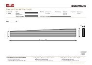
LOADING SEQUENCE<br />
Loading plans<br />
Loading sequence in accordance<br />
with customer’s request.<br />
Mayr-Melnhof Kaufmann may<br />
deviate from the loading sequence<br />
in the case of technical impracticability.<br />
The lorry will be loaded at our own<br />
discretion without specifying the<br />
loading sequence.<br />
The transport costs include 2,5<br />
hours for unloading of the lorry.<br />
Version 1 / 2011<br />
M1 BSP crossplan<br />
At the same time as approval is given for production, detailed loading plans are drawn up in<br />
consultation with the customer. Agreement must be reached here between the customer’s<br />
wishes and the practical possibilities of unloading.<br />
The legal regulations regarding securing of the cargo have been tightened up considerably<br />
recently and compliance with them is inspected very carefully, the result being that unfortunately<br />
it is often necessary to deviate from the best loading sequences.<br />
max. 4.000<br />
1.200<br />
Delivery address:<br />
Delivery date: Week:<br />
Day:<br />
Time:<br />
Contact:<br />
Tel.:<br />
4100<br />
3000<br />
1100<br />
Delivery address:<br />
Delivery date: Week:<br />
Day:<br />
Time:<br />
Contact:<br />
Tel.:<br />
950 950<br />
13.600<br />
Loading sequence<br />
Deliver off cuts: � Yes / � No<br />
Type of unloading: � Crane / � forklift<br />
Max. package size: kg<br />
Max. lorry load: 50 m 3 / 24 t<br />
Max. element size: 3,0 x 16,5 m<br />
Excess width: from 2,5 m<br />
Lorry no.:<br />
Deliver off cuts: � Yes / � No<br />
Max. package size: kg<br />
Max. lorry load: 50 m 3 / 24 t<br />
Max. element size: 3,0 x 16,5 m<br />
Excess width: from 2,5 m<br />
Lorry no.:<br />
Mayr-Melnhof Kaufmann 23
M1 BSP crossplan<br />
Transport procedure<br />
Flatwise transport<br />
Upright transport<br />
Storage<br />
Lifting devises<br />
24 Mayr-Melnhof Kaufmann<br />
TRANSPORT<br />
The transport will be scheduled once the loading plans and delivery dates have been defi ned.<br />
Special transports are almost always necessary because most of the loads contain components<br />
with lengths exceeding 13,60 m and / or widths or heights exceeding 2,50 m.<br />
These special tranports require national and international road use permits and should,<br />
therefore, only be carried out by carriers familiar with them and equipped for the task.<br />
The transport costs referred to include 2,5 hours for unloading of the lorry at the building site.<br />
Each additional hour of the lorry’s waiting time will be invoiced additionally if delays occur<br />
during unloading.<br />
The elements may be transported either upright or fl at.<br />
Component deliveries lying fl at are particularly appropriate for panels with less machining<br />
(e.g. ceiling elements) or raw panels. This is also the more cost-eff ective variation for widths<br />
up to 3,00 m as platform semi-trailers may be used without additional structures. Appropriate<br />
ex works protection against dirt is guaranteed by packaging in plastic foil.<br />
Upright element transport is used primarily for material with a high level of machining such<br />
as walls with window and door cut-outs, visible components, and similar. The use of fl atbed<br />
semi-trailers with appropriate loading area structures is, however, more expensive than transport<br />
elements lying fl at using platform semi-trailers.<br />
The basic principles of timber storage must be observed where it is necessary to store<br />
M1 BSP crossplan.<br />
M1 BSP crossplan elements may be provided with assembly aids. These are used to manipulate<br />
the elements at the plant and on the building site. Loops or special screw systems will be<br />
used depending on the type of component and size. The number of assembly aids attached<br />
depends on the safety requirements and the measurements of the relevant components.<br />
Version 1 / 2011
INVOICING SYSTEM<br />
Invoicing<br />
Surcharges<br />
Version 1 / 2011<br />
M1 BSP crossplan<br />
The basis of every M1 BSP crossplan invoice is the unit m 2 and the surface condition in industrial<br />
quality.<br />
The smallest circumscribed rectangle based on the fi nished dimension of the nearest grid<br />
width is always applicable as the invoicing area. This gross measuring system also includes<br />
recalculation of all openings typical of residential buildings. Generally speaking, the basic<br />
calculation includes free, right-angled cutting to format of each element.<br />
All additional services are presented in a transparent surcharge system to make the pricing<br />
policy easy and clear for the customer.<br />
1. Surface condition:<br />
Additional price for one-sided surface in standard quality. Price basis per m 2<br />
Additional price for two-sided surface in standard quality. Price basis per m 2<br />
2. Element machining:<br />
Additional price for machining operations such as door and window openings, bevel cuts<br />
in the gable region, cut to length and notches in a number typical for residential buildings.<br />
Price basis per m 2<br />
3. Rebates and profi les:<br />
Milling of all conventional rebate systems such as butt board rebates and stepped rebates<br />
in all element widths. Price basis per linear metre.<br />
4. Assembly aids:<br />
Supply of appropriate aids for safe manipulation and assembly of wall and ceiling elements.<br />
Price basis per unit.<br />
5. Transport:<br />
Documentation of the transportation charges. Price basis per transport<br />
6. Special custom joinery:<br />
Additional price for custom joinery works (e.g. special drilled holes, mortices, etc.) using<br />
5-axis machining robot, invoiced according to actual time and expenses. Price basis<br />
all-in price<br />
7. Special surfaces:<br />
Additional pricing for customized orders, such as diff erent wood species, special<br />
surfaces and other customized requests. Price basis per m²<br />
Mayr-Melnhof Kaufmann 25
M1 BSP crossplan<br />
AW 01<br />
I<br />
outside inside<br />
AW 02<br />
outside inside<br />
AW 03<br />
outside inside<br />
AW 04<br />
outside inside<br />
26 Mayr-Melnhof Kaufmann<br />
Wall cross-section from<br />
outside to inside<br />
CONSTRUCTION DETAILS<br />
WALL CONSTRUCTION<br />
Thickness<br />
mm<br />
Timber larch cladding 20,0<br />
Timber spruce battens (30 / 60) 30,0<br />
Vapour-permeable membrane<br />
Sd ≤ 0,3 m<br />
–<br />
Wood fi bre insulation board 100,0<br />
M1 BSP crossplan 95,0<br />
Gypsum fi breboard (12,5 mm) 12,5<br />
Overall<br />
thickness mm<br />
Fire protection Sound<br />
insulation<br />
258 REI 90*<br />
Airborne noise<br />
R W 42 dB<br />
Exterior wall / with timber façade / not ventilated / with service layer<br />
Exterior wall / with plaster façade / not ventilated / with service layer<br />
Wall cross-section from<br />
outside to inside<br />
Thickness<br />
mm<br />
Plaster 4,0<br />
Rockwool MW-PT<br />
120,0<br />
Plaster-base sheeting<br />
M1 BSP crossplan 98,0<br />
Timber spruce battens (40 / 50)<br />
on bracket<br />
70,0<br />
Glasswool [0,040; R = 16]<br />
d = 50 mm<br />
Gypsum fi breboard (2 × 12,5 mm)<br />
or Gypsum fi breboard (2 × 10 mm)<br />
25,0<br />
Overall<br />
thickness mm<br />
Fire protection Sound<br />
insulation<br />
317 REI 120*<br />
Airborne<br />
noise<br />
R W 53 DB<br />
Thermal<br />
insulation<br />
U value<br />
0,35 [W / m 2 K]<br />
Wall cross-section from<br />
Thickness Overall Fire protection Sound Thermal<br />
outside to inside<br />
mm thickness mm<br />
insulation insulation<br />
Exterior wall cladding 20,0<br />
339 REI 90*<br />
Airborne<br />
noise<br />
RW 51 DB<br />
U value<br />
0,19 [W / m2 Timber spruce battens (30 / 60) 30,0<br />
Vapour-permeable membrane Sd ≤ 0,3 M –<br />
Timber spruce battens (50 / 60)<br />
Rockwool [0,040; R ≥ 70]<br />
50,0<br />
Timber battens spruce (80 / 60)<br />
Rockwool [0,040; R ≥ 70]<br />
M1 BSP crossplan<br />
Timber spruce battens (40 / 50)<br />
80,0<br />
98,0<br />
K]<br />
on bracket<br />
Rockwool [0,040; R ≥ 28] d = 50<br />
50,0<br />
Gypsum fi breboard (12,5 mm) or<br />
Gypsum fi breboard (10 mm)<br />
12,5<br />
Thermal<br />
insulation<br />
U value<br />
0,20 [W / m 2 K]<br />
Exterior wall / with plaster façade / not ventilated / without service layer<br />
Wall cross-section from<br />
outside to inside<br />
Thickness<br />
mm<br />
Plaster 4,0<br />
Rockwool MW-PT<br />
Plaster-base sheeting<br />
120,0<br />
M1 BSP crossplan 95,0<br />
Overall<br />
thickness mm<br />
* according classifi cation reports M1 BSP crossplan of HFA<br />
Fire protection Sound<br />
insulation<br />
219 REI 60*<br />
Airborne noise<br />
R W 38 DB<br />
Source: www.dataholz.com, catalogue «Bauphysikalisch geprüfter Bauteile für den Holzbau»<br />
Thermal<br />
insulation<br />
U value<br />
0,26 [W / m 2 K]<br />
Version 1 / 2011
CONSTRUCTION DETAILS<br />
WALL CONSTRUCTION<br />
Partition wall / without service layer<br />
Wall cross-section from<br />
left to right<br />
Partition wall / without service layer<br />
Partition wall / with service layer<br />
Wall cross-section from<br />
left to right<br />
Partition wall / with service layer<br />
Version 1 / 2011<br />
Thickness<br />
mm<br />
Gypsum fi breboard 12,5 mm 12,5<br />
M1 BSP crossplan 95,0<br />
Impact noise insulation panel MW-T 30,0<br />
M1 BSP crossplan<br />
Timber spruce battens (40 / 50)<br />
95,0<br />
on bracket<br />
Glass wool [0,040; R = 16]<br />
d = 50 mm<br />
50,0<br />
Gypsum fi breboard 12,5 mm 12,5<br />
Wall cross-section from<br />
left to right<br />
Thickness<br />
mm<br />
M1 BSP crossplan 95,0<br />
Impact noise insulation panel<br />
MW-T<br />
30,0<br />
M1 BSP crossplan 95,0<br />
Wall cross-section from<br />
left to right<br />
Thickness<br />
mm<br />
Gypsum fi breboard 12,5 mm 12,5<br />
M1 BSP crossplan 95,0<br />
Impact noise insulation panel MW-T 30,0<br />
M1 BSP crossplan 95,0<br />
Gypsum fi breboard 12,5 mm<br />
Construction without gypsum<br />
fi breboards<br />
12,5<br />
Thickness<br />
mm<br />
Gypsum fi breboard 12,5 mm 12,5<br />
Rockwool [0,04I; R = 27] d = 60 mm<br />
Timber spruce battens (40/50) 70,0<br />
on bracket<br />
M1 BSP crossplan 98,0<br />
Timber spruce battens (40/50)<br />
on bracket<br />
70,0<br />
Rockwool [0,04I; R = 27] d = 60 mm<br />
Gypsum fi breboard 12,5 mm 12,5<br />
Overall<br />
thickness mm<br />
220 REI 60*<br />
Overall<br />
thickness mm<br />
245<br />
Overall<br />
thickness mm<br />
Fire protection Sound<br />
insulation<br />
295 REI 90*<br />
Overall<br />
thickness mm<br />
* according classifi cation reports M1 BSP crossplan of HFA<br />
Fire protection Sound<br />
insulation<br />
Fire protection<br />
263 REI 90*<br />
Airborne noise<br />
R W 48 dB<br />
Fire protection Sound<br />
insulation<br />
REI 90*<br />
Airborne noise<br />
R W 56 dB<br />
Airborne noise<br />
R W 62 DB<br />
Sound<br />
insulation<br />
Airborne noise<br />
R W 58 DB<br />
M1 BSP crossplan<br />
Thermal<br />
insulation<br />
U value<br />
0,39<br />
[W / m 2 K]<br />
Thermal<br />
insulation<br />
U value<br />
0,38 [W / m 2 K]<br />
220 48 dB 0,39 [W / m 2 K]<br />
Source: www.dataholz.com, catalogue «Bauphysikalisch geprüfter Bauteile für den Holzbau»<br />
Thermal<br />
insulation<br />
U value<br />
0,27 [W / m2K] Thermal<br />
insulation<br />
U value<br />
0,25 [W / m 2 K]<br />
WTW 01<br />
inside inside<br />
WTW 02<br />
inside inside<br />
WTW 03<br />
inside inside<br />
WTW 04<br />
inside inside<br />
Mayr-Melnhof Kaufmann 27
M1 BSP crossplan<br />
IW 01<br />
inside inside<br />
IW 02<br />
inside inside<br />
FD 01<br />
outside<br />
inside<br />
FD 02<br />
outside<br />
inside<br />
28 Mayr-Melnhof Kaufmann<br />
Interior wall / without service layer<br />
Wall cross-section from<br />
outside to inside<br />
Interior wall / without service layer<br />
CONSTRUCTION DETAILS<br />
WALL CONSTRUCTION<br />
Thickness<br />
mm<br />
Overall<br />
thickness mm<br />
Flat roof / suspended / without rear ventilation<br />
Flat roof / suspended / without rear ventilation<br />
Fire<br />
protection<br />
M1 BSP crossplan 95,0 95 REI 60*<br />
Wall cross-section from<br />
outside to inside<br />
Wall cross-section from<br />
outside to inside<br />
Thickness<br />
mm<br />
Gravel fi ll<br />
Separating fl eece [Sd ≤ 0,2M]<br />
50,0<br />
Extruded polystyrene 80,0<br />
Bituminous cardboard 9,0<br />
Rockwool [0,040; R = 16]<br />
Vapour barrier Sd ≥ I500M<br />
150,0<br />
M1 BSP crossplan ceiling or<br />
acc. to structural requirement<br />
140<br />
Timber spruce battens suspended<br />
Glasswool [0,040; R = 16] d = 50 mm<br />
70,0<br />
Gypsum fi breboard 12,5<br />
Wall cross-section from<br />
outside to inside<br />
Thickness<br />
mm<br />
Gypsum fi breboard 1 x 12,5 mm 25,0<br />
M1 BSP crossplan 78,0<br />
Gypsum fi breboard 1 x 12,5 mm 25,0<br />
Thickness<br />
mm<br />
Roofi ng membrane<br />
Fibre insulation board 2 x 100 mm 200,0<br />
Vapour barrier bituminous<br />
(= emergency roof)<br />
M1 BSP crossplan<br />
0,2<br />
Ceiling 118 mm or according<br />
to structural requirement<br />
118<br />
Bracket / air space 50,0<br />
Gypsum fi breboard 12,5<br />
Overall<br />
thickness mm<br />
Overall<br />
thickness mm<br />
Fire<br />
protection<br />
512 REI 90*<br />
Overall<br />
thickness mm<br />
* according classifi cation reports M1 BSP crossplan of HFA<br />
Fire<br />
protection<br />
128 REI 60*<br />
Fire<br />
protection<br />
381 REI 60*<br />
Sound<br />
insulation<br />
Airborne noise<br />
R W 33 dB<br />
Sound<br />
insulation<br />
Airborne noise<br />
R W 38 dB<br />
Source: www.dataholz.com, catalogue «Bauphysikalisch geprüfter Bauteile für den Holzbau»<br />
Sound<br />
insulation<br />
Airborne<br />
noise<br />
R W 47 dB<br />
Sound<br />
insulation<br />
Airborne<br />
noise<br />
R W 47 dB<br />
Thermal<br />
insulation<br />
U value<br />
1,1 [W / m 2 K]<br />
Thermal<br />
insulation<br />
U value<br />
0,87 [W / m 2 K]<br />
Thermal<br />
insulation<br />
U value<br />
0,12 [W / m 2 K]<br />
Thermal<br />
insulation<br />
U value<br />
0,15 [W / m 2 K]<br />
Version 1 / 2011
CONSTRUCTION DETAILS<br />
CEILING CONSTRUCTION<br />
Floor / dry / not suspended<br />
Floor cross-section<br />
Thickness<br />
top to bottom<br />
mm<br />
Gypsum fi breboard 10,0<br />
Heraklith-Floor (gypsum fi breboard) 10,0<br />
Heraklith-Floor (Lightweight wood<br />
wool building board)<br />
75,0<br />
Heralan TPS 15 / 13<br />
Impact noise insulation<br />
13,0<br />
Fill (grit) 50,0<br />
Drip protection fi lm –<br />
M1 BSP crossplan (or according<br />
to structural requirement)<br />
160,0<br />
Floor / wet / suspended<br />
Floor cross-section<br />
Thickness<br />
top to bottom<br />
mm<br />
Cement screed / anhydrite screed 50,0<br />
Separating layer plastic sheeting –<br />
Impact noise insulation MW-T 30,0<br />
Polystyrene EPS-W (0,041) 30,0<br />
Fill (grit) 50,0<br />
Drip protection fi lm –<br />
M1 BSP crossplan (or acc. to<br />
structural requirement)<br />
140,0<br />
Timber battens on insulating strips 24,0<br />
Gypsum fi breboard 12,5<br />
Floor cross-section<br />
top to bottom<br />
Cement screed / anhydrite<br />
screed<br />
Separating layer plastic<br />
sheeting<br />
Impact noise insulation<br />
MW-T 35 / 30<br />
M1 BSP crossplan (or acc.<br />
to structural requirement)<br />
Floor / dry / suspended<br />
Version 1 / 2011<br />
Thickness<br />
mm<br />
50,0<br />
–<br />
30,0<br />
118,0<br />
Floor cross-section Thickness<br />
top to bottom<br />
mm<br />
OSB tongue and groove panel 18,0<br />
Heraklith BM<br />
Separating layer<br />
25,0<br />
Heralan-DF 60,0<br />
Grit fi ll<br />
M1 BSP crossplan<br />
60,0<br />
Ceiling 160 mm or according<br />
to static requirement<br />
160,0<br />
Heraklith BM 25,0<br />
Spring rail 50,0<br />
Gypsum fi breboard 12,5 mm 12,5<br />
Overall<br />
thickness mm<br />
Fire<br />
protection<br />
318 REI 90*<br />
Overall<br />
thickness mm<br />
Overall<br />
thickness mm<br />
Fire<br />
protection<br />
337 REI 60*<br />
Fire<br />
protection<br />
198 REI 60*<br />
Overall<br />
thickness mm<br />
Fire<br />
protection<br />
411 REI 90*<br />
Sound<br />
insulation<br />
Airborne noise<br />
R W 65 dB<br />
Impact noise<br />
L'nTw 50 dB<br />
Sound<br />
insulation<br />
Airborne noise<br />
R W 60 dB<br />
Impact noise<br />
L'nTw 48 dB<br />
Sound<br />
insulation<br />
Airborne noise<br />
R W 48 dB<br />
Impact noise<br />
L'nTw 67 dB<br />
Sound<br />
insulation<br />
Airborne noise<br />
R W 58 dB<br />
Impact noise<br />
L'nTw 48 dB<br />
* according classifi cation reports M1 BSP crossplan of HFA<br />
Source: www.dataholz.com, catalogue «Bauphysikalisch geprüfter Bauteile für den Holzbau»<br />
M1 BSP crossplan<br />
Thermal<br />
insulation<br />
U value<br />
0,38 [W / m 2 K]<br />
Thermal<br />
insulation<br />
U value<br />
0,32 [W / m 2 K]<br />
Thermal<br />
insulation<br />
U value<br />
0,53 [W / m 2 K]<br />
Thermal<br />
insulation<br />
U value<br />
0,27 [W / m 2 K]<br />
GD 01<br />
top<br />
bottom<br />
GD 02<br />
top<br />
bottom<br />
GD 03<br />
top<br />
bottom<br />
GD 04<br />
top<br />
bottom<br />
Mayr-Melnhof Kaufmann 29
M1 BSP crossplan<br />
SO 01<br />
Connections:<br />
Outside wall plinth connection<br />
SO 02<br />
30 Mayr-Melnhof Kaufmann<br />
Wall construction<br />
see component AW02<br />
Façade attachment<br />
acc. to structural design<br />
Mortar filler<br />
Insect screen<br />
Wall construction<br />
see component AW02<br />
Facade attachment<br />
acc. to static design<br />
Bird screen<br />
Level of external site<br />
Precast concrete element<br />
Perimeter insulation<br />
5,0 cm<br />
XPS-panel with drainage 5,0 cm<br />
Damp-proofing -- cm<br />
Reinforced concrete wall<br />
acc. to stat. req.<br />
20,0 cm<br />
Insulation<br />
approx. 50 cm<br />
0,5 cm<br />
min 30 cm<br />
min 30 cm<br />
CONSTRUCTION<br />
DETAILS<br />
Glue<br />
butt joints<br />
convection-tight<br />
Separating strip<br />
Plinth plaster 0,5 cm<br />
XPS-panel 5,0 cm<br />
Damp-proofing -- cm<br />
Reinforced concrete<br />
wall acc. to stat. req.<br />
20,0 cm<br />
Internal render 0,5 cm<br />
Glue<br />
butt joints<br />
convection-tight<br />
Separating strip<br />
Floor covering Parquet 2,0 cm<br />
Cement screed 5,0 cm<br />
Separating layer according<br />
to Austrian standard B2232<br />
-- cm<br />
Impact noise insulation 2,0 cm<br />
Bonded fill 5,0 cm<br />
Damp-proofing -- cm<br />
Reinforced concrete ceiling<br />
acc. to stat. req.<br />
20 cm<br />
Internal render 0,5 cm<br />
Precast concrete element<br />
Perimeter insulation<br />
5,0 cm<br />
XPS-panel with drainage 5,0 cm<br />
Damp-proofing -- cm<br />
Reinforced concrete plinth<br />
according to stat. req.<br />
15,0 cm<br />
Cellular glass 5,0 cm<br />
Gypsum fibreboard or drywall 1,25 cm<br />
Floor covering Parquet 2,0 cm<br />
Cement screed 5,0 cm<br />
Separating layer according<br />
to Austrian standard B2232<br />
-- cm<br />
Impact noise insulation 2,0 cm<br />
Bonded fill 5,0 cm<br />
Damp-proofing -- cm<br />
Reinforced concrete ceiling<br />
acc. to stat. req.<br />
20 cm<br />
Thermal insulation 7,5 cm<br />
Version 1 / 2011
CONSTRUCTION<br />
DETAILS<br />
DE 01<br />
Connections:<br />
Exterior wall pitched roof connection<br />
DA 01<br />
Version 1 / 2011<br />
Wall construction<br />
see component AW02<br />
Insect screen<br />
Wall construction<br />
see component AW02<br />
M1 BSP crossplan<br />
95 38 GL<br />
RA<br />
53 60 GM<br />
Glue<br />
butt joints<br />
convection-tight<br />
Separating strip<br />
Glue<br />
butt joints convection-tight<br />
Construction:<br />
see component GD01<br />
Edges and joint finishing acc.<br />
to machining guidelines<br />
Noise reducing separation<br />
Wall construction<br />
see component AW02<br />
Edges and joint finishing acc.<br />
to machining guidelines<br />
Roof covering -- cm<br />
Roof battens 3/5 3,0 cm<br />
Counter battens 4/6 4,0 cm<br />
Vapour-permeable roofing<br />
membrane<br />
20,0 cm<br />
Full formwork 2,5 cm<br />
Spars according to requirement 16 cm<br />
Insulation between -- cm<br />
Battens on bracket 4/5 5 cm<br />
Insulation between<br />
-- cm<br />
Vapour barrier<br />
-- cm<br />
Gypsum fibreboard<br />
1,25 cm<br />
Edges and joint finishing acc.<br />
to machining guidelines<br />
Glue vapour barrier to<br />
cross-laminated timber panel<br />
Mayr-Melnhof Kaufmann 31
M1 BSP crossplan<br />
Connections:<br />
Exterior wall fl at roof connection<br />
DA 02<br />
32 Mayr-Melnhof Kaufmann<br />
Roof parapet attachment<br />
according to structural design<br />
Facade attachment<br />
acc. to structural design<br />
Wall construction<br />
see component AW02<br />
Gradient min. 2%<br />
CONSTRUCTION<br />
DETAILS<br />
min 30 cm<br />
Tapered insulation<br />
roof construction<br />
see component FD02<br />
Gradient min. 2%<br />
Gradient insulation panel EPS<br />
Edges and joint finishing<br />
acc. to machining guidelines<br />
Glue butt joints convection-tight<br />
Version 1 / 2011
CONSTRUCTION<br />
DETAILS<br />
General<br />
Connection technique<br />
Vertical section<br />
In slender buildings tensile<br />
bracing stays must be created!<br />
Shear angle<br />
e.g. BMF 105 with rib<br />
Spacing = approx. 90 cm<br />
or acc. to stat. requirement<br />
Mortar filler<br />
Protection against<br />
rising damp<br />
Connection technique<br />
Horizontal section<br />
Version 1 / 2011<br />
Self-tapping wood screws<br />
M8/e = 33 cm<br />
or acc. to stat. requirement<br />
HSA-M10x120<br />
HSA-M10x120<br />
Shear angle<br />
Spacing = approx. 90 cm<br />
e.g. BMF 105 with rib<br />
or acc. to stat. requirement<br />
Noise reducing separation<br />
(if necessary)<br />
Self-tapping wood screws<br />
M8/e = 33 cm<br />
or acc. to stat. requirement<br />
Self-tapping wood screws<br />
M8/ e = 33 cm<br />
or acc. to stat. requirement<br />
Self-tapping wood screws<br />
M8/ e = 33 cm<br />
or acc. to stat. requirement<br />
Stepped rebate<br />
Butt board rebate<br />
Rebate height = 27 mm<br />
M1 BSP crossplan<br />
All joints (vertical or horizontal) of the M1 BSP crossplan elements shall be sealed by applying<br />
a permanent elastic sealing tape (recommendation).<br />
If required<br />
execute sound-proof and airtight<br />
Full thread screws<br />
arranged in pairs<br />
e.g. WT-T; d = 8,2 mm; e = 33 cm<br />
or acc. to stat. requirement<br />
H<br />
h/2<br />
h/2<br />
50<br />
9090<br />
Exterior corner right-angled<br />
Connection to partition wall<br />
Exterior corner with mitre cut<br />
Self-tapping wood screws<br />
M6/ e = 25 cm<br />
or acc. to stat. requirement<br />
Self-tapping wood screws<br />
M8/ e = 33 cm or according<br />
to stat. requirement<br />
Mayr-Melnhof Kaufmann 33
M1 BSP crossplan<br />
Sample tender text<br />
M1 BSP crossplan –<br />
general material<br />
description<br />
Manufacturer<br />
Qualities<br />
M1 BSP crossplan –<br />
Approvals and<br />
certifi cations<br />
34 Mayr-Melnhof Kaufmann<br />
TENDER TEXT<br />
The following tender text refers to a shell construction made from cross-laminated timber<br />
panels and is intended to be used as a guideline which may be adapted to the relevant building<br />
project and the specifi c circumstances. Custom joinery works and component joints<br />
must be defi ned as accurately as possible with sketches and drawings as necessary.<br />
We will be grateful to supply the sample text in MS Word format on request.<br />
Multi-layered glued, large-formatted panel elements, minimum width 2.40 m, made of spruce<br />
for structural use as wall, ceiling or roof elements. The planed lamella layers are each arranged<br />
off set at 90° to each other and glued together under high pressure (at least 1,2 N/mm 2 ) over<br />
the entire surface.<br />
The dimensionally stable elements are layed-up symmetrically to the central plane in crosssection.<br />
Only Melamine-adhesives approved for load-bearing timber components in interior and exterior<br />
use (class of use 1 and 2 according to ÖNORM EN 1995-1-1) are permitted. The moisture<br />
content of the lamellas used is 12 % (+/- 2 %). Surface quality – unless noted otherwise in the<br />
position – is industrial quality. The M1 BSP crossplan panels may not be fi ngerjointed (panel<br />
to panel connection).<br />
In order to prevent uncontrolled stress cracks, the individual lamellas may not be edge-glued<br />
together on the narrow side.<br />
The airtightness of the 3-, 5- or 7-layered M1 BSP crossplan element is a basic requirement.<br />
Mayr-Melnhof Kaufmann Gaishorn GmbH<br />
8783 Gaishorn am See 182 / Austria<br />
T +43 3617 2151-0<br />
gaishorn@mm-kaufmann.com<br />
www.mm-kaufmann.com<br />
Industrial quality: Industrial quality is intended for construction applications, for subsequent<br />
installations by the customer (e.g. plasterboard). The top lamellas are exclusively sorted<br />
according to the sorting criteria of the load-bearing strength C24 according to EN 338.<br />
A proportion of max. 10 % C16 is permissible (ETA-09 / 0036) Color variations of individual<br />
lamellas (e.g. blue stain), as well as loose knots, ingrown bark and resin pockets are permitted.<br />
Isolated gaps in the outer layers, glue stains as well as isolated pressure points and<br />
markings may appear.<br />
Standard quality: With additional requirements for a visual application. Stringent visual criteria<br />
for outer layers are applied in addition to the sorting criteria for load-bearing strength.<br />
Selected raw material with healthy, intergrown knots. A few isolated defects such as loose<br />
knots and small resin pockets are permissible. The surface is planed and sanded.<br />
Cross-laminated timber requires a certifi cate of usability by means of European technical<br />
approvals (cross-laminated timber – solid panel-shaped timber construction elements for<br />
load-bearing components in structures, e.g. ETA-09/0036) or German technical approval<br />
(e.g. Z-9.1-638 for M1 BSP crossplan), in which the panel construction and layer thickness<br />
as well as strength and stiff ness characteristics are specifi ed.<br />
Version 1 / 2011
TENDER TEXT<br />
Calculation<br />
Position text<br />
Pos. xx<br />
M1 BSP crossplan<br />
walls<br />
Pos. xx<br />
M1 BSP crossplan<br />
ceilings<br />
Version 1 / 2011<br />
M1 BSP crossplan<br />
The manufacture of high-quality cross-laminated timber must be ensured by means of factory<br />
production control and additional third-party inspection by accredited inspection agencies.<br />
With regard to sustainability and building biology, PEFC certifi ed material must be used and<br />
the harmlessness of the product in terms of building biology must be demonstrated (e.g. IBR<br />
seal of quality from the Rosenheim Institute of Building Biology).<br />
The manufacture of door and window openings must be included, invoicing will be according<br />
to the extent of the area. All connecting devises, steel components and joining components<br />
such as butt boards, sealing materials and tolerance equalization aids are to be included in<br />
the unit prices.<br />
The elements must be protected against water and dirt during transport and assembly.<br />
Manufacture, delivery and assembly of cross-laminated timber elements as wall panels, wall<br />
height = max. 3,0 m, element length = max. 16,50 m; stepped rebate; top layers in vertical<br />
direction (= cross-wise direction of element)<br />
Exterior wall elements: M1 BSP crossplan 98 mm 3-s DQ<br />
Element thickness: 98 mm, 3-layer, top layers in crosswise direction to element (DQ)<br />
Element width: m (max. 3,0 m)<br />
Element length: m (max. 16,5 m)<br />
Surface: Industrial quality<br />
Product off ered:<br />
m² á EUR / m² Total EUR<br />
Interior wall elements: M1 BSP crossplan 78 mm 3-s DQ<br />
Element thickness: 78 mm, 3-layer, top layers in crosswise direction to element (DQ)<br />
Element width: m (max. 3,0 m)<br />
Element length: m (max. 16,5 m)<br />
Surface: Industrial quality<br />
Product off ered:<br />
m² á EUR / m² Total EUR<br />
Manufacture, delivery and assembly of cross-laminated timber elements as ceiling panels,<br />
design as n-fi eld beams, element length = max. 16,50 m; butt board rebate and joining to the<br />
beams or exterior walls by screwing.<br />
Ceiling elements: M1 BSP crossplan 134 mm 5-s DL (or equivalent)<br />
Element thickness: 134 mm, 5-layer, top layers in longitudinal direction<br />
to element (DL)<br />
Element width: m (max. 3,0 m Elementbreite)<br />
Element length: m (max. 16,5 m)<br />
Surface: Industrial quality<br />
Product off ered:<br />
m² á EUR / m² Total EUR<br />
Mayr-Melnhof Kaufmann 35
Our factory at Gaishorn<br />
INNOVATIVE SOLUTIONS<br />
FOR DEMANDING CUSTOMERS<br />
It was in the Styrian municipality of Gaishorn am See in<br />
Austria that the most important production site for laminated<br />
timber was fi rst set up in 1991. Known by the name of «Systemholz»,<br />
these standardised laminated timber beams met<br />
with a brisk demand in the markets of Italy, Germany and<br />
Austria.<br />
After gradually expanding the factory‘s production capacity<br />
and investing in a new manufacturing facility for its innovative<br />
cross-laminated timber panels, the Gaishorn site now houses<br />
three plants for laminated and one for cross-laminated timber,<br />
plus a sorting plant and nineteen drying kilns.<br />
Since 2009, the plants have been operating under the name<br />
of Mayr-Melnhof Kaufmann Gaishorn. With a capacity of approx.<br />
200.000 m 3 for laminated timber and 60.000 m 3 for<br />
cross-laminated timber, plus a CNC centre for cross-laminated<br />
panels, the site is one of the leading and most modern<br />
production facilities for wood engineering materials in<br />
Europe.<br />
Your distributor:<br />
The basic raw material used in laminated timber and<br />
M1 BSP crossplan is locally grown wood from sustainably<br />
managed forests. State-of-the-art electronic sorting and testing<br />
machines guarantee the highest quality.<br />
Effi cient high-frequency press technology is available for fulfi<br />
lling unusual customer wishes in a short space of time. Internal<br />
and external inspections are conducted by independent<br />
testing institutes on a regular basis to ensure the highest<br />
possible product quality and safety.<br />
Mayr-Melnhof Kaufmann Gaishorn GmbH<br />
Nr. 182<br />
8783 Gaishorn am See<br />
Austria<br />
T +43 3617 2151 0<br />
F +43 3617 2151 10<br />
gaishorn@mm-kaufmann.com<br />
www.mm-kaufmann.com