Broch
Broch
Broch

Create successful ePaper yourself
Turn your PDF publications into a flip-book with our unique Google optimized e-Paper software.
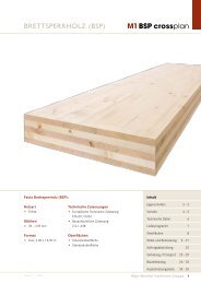
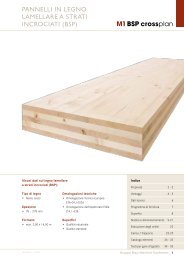
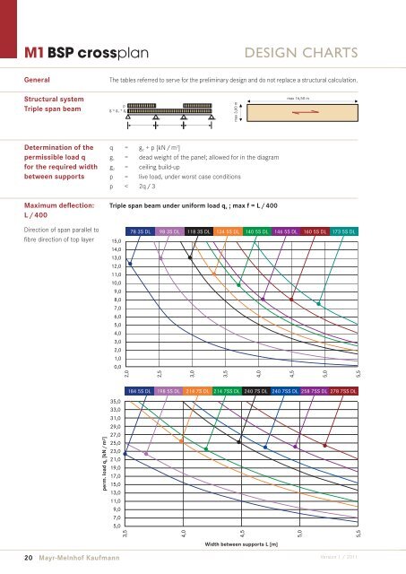
M1 BSP crossplan<br />
General<br />
Structural system<br />
Triple span beam<br />
Determination of the<br />
permissible load q<br />
for the required width<br />
between supports<br />
Maximum defl ection:<br />
L / 400<br />
Direction of span parallel to<br />
fi bre direction of top layer<br />
perm. load q k [kN / m²]<br />
p<br />
g = g + g 1 2<br />
20 Mayr-Melnhof Kaufmann<br />
q = g 2 + p [kN / m 2 ]<br />
g 1 = dead weight of the panel; allowed for in the diagram<br />
g 2 = ceiling build-up<br />
p = live load, under worst case conditions<br />
p < 2q / 3<br />
Triple span beam under uniform load q k ; max f = L / 400<br />
15,0<br />
14,0<br />
13,0<br />
12,0<br />
11,0<br />
10,0<br />
9,0<br />
8,0<br />
7,0<br />
6,0<br />
5,0<br />
4,0<br />
3,0<br />
2,0<br />
1,0<br />
0,0<br />
35,0<br />
33,0<br />
31,0<br />
29,0<br />
27,0<br />
25,0<br />
23,0<br />
21,0<br />
19,0<br />
17,0<br />
15,0<br />
13,0<br />
11,0<br />
9,0<br />
7,0<br />
5,0<br />
2,0<br />
2,5<br />
3,0<br />
3,5<br />
max 3,00 m<br />
DESIGN CHARTS<br />
The tables referred to serve for the preliminary design and do not replace a structural calculation.<br />
3,5<br />
4,0<br />
max 16,50 m<br />
78 3S DL 98 3S DL 118 3S DL 134 5S DL 140 5S DL 146 5S DL 160 5S DL 173 5S DL<br />
184 5S DL 198 5S DL 214 7S DL 214 7SS DL 240 7S DL 240 7SS DL 258 7SS DL 278 7SS DL<br />
4,0<br />
4,5<br />
Width between supports L [m]<br />
4,5<br />
5,0<br />
5,0<br />
5,5<br />
5,5<br />
Version 1 / 2011